EP0704830B1 - Dispositif électronique impulsionnel de surveillance d'article utilisant les techniques de système expert pour l'optimisation dynamique - Google Patents
Dispositif électronique impulsionnel de surveillance d'article utilisant les techniques de système expert pour l'optimisation dynamique Download PDFInfo
- Publication number
- EP0704830B1 EP0704830B1 EP95114177A EP95114177A EP0704830B1 EP 0704830 B1 EP0704830 B1 EP 0704830B1 EP 95114177 A EP95114177 A EP 95114177A EP 95114177 A EP95114177 A EP 95114177A EP 0704830 B1 EP0704830 B1 EP 0704830B1
- Authority
- EP
- European Patent Office
- Prior art keywords
- noise
- phase
- noise environment
- transmit
- receiver
- Prior art date
- Legal status (The legal status is an assumption and is not a legal conclusion. Google has not performed a legal analysis and makes no representation as to the accuracy of the status listed.)
- Expired - Lifetime
Links
Images


Classifications
-
- G—PHYSICS
- G08—SIGNALLING
- G08B—SIGNALLING OR CALLING SYSTEMS; ORDER TELEGRAPHS; ALARM SYSTEMS
- G08B13/00—Burglar, theft or intruder alarms
- G08B13/22—Electrical actuation
- G08B13/24—Electrical actuation by interference with electromagnetic field distribution
- G08B13/2402—Electronic Article Surveillance [EAS], i.e. systems using tags for detecting removal of a tagged item from a secure area, e.g. tags for detecting shoplifting
- G08B13/2465—Aspects related to the EAS system, e.g. system components other than tags
- G08B13/2482—EAS methods, e.g. description of flow chart of the detection procedure
-
- G—PHYSICS
- G08—SIGNALLING
- G08B—SIGNALLING OR CALLING SYSTEMS; ORDER TELEGRAPHS; ALARM SYSTEMS
- G08B13/00—Burglar, theft or intruder alarms
- G08B13/22—Electrical actuation
- G08B13/24—Electrical actuation by interference with electromagnetic field distribution
- G08B13/2402—Electronic Article Surveillance [EAS], i.e. systems using tags for detecting removal of a tagged item from a secure area, e.g. tags for detecting shoplifting
- G08B13/2465—Aspects related to the EAS system, e.g. system components other than tags
- G08B13/2468—Antenna in system and the related signal processing
- G08B13/2471—Antenna signal processing by receiver or emitter
Definitions
- This invention relates generally to electronic article surveillance (EAS) and pertains more particularly to improved EAS systems.
- One present commercially implemented EAS system of the assignee hereof has a transmitter which radiates a pulsed magnetic field into a surveillance area wherein it is desired to note the presence of articles bearing EAS tags, also referred to in the EAS industry as labels or markers.
- EAS tags also referred to in the EAS industry as labels or markers.
- a receiver which is enabled between successively spaced transmitter field radiations, detects the response signal of the tag and initiates an alarm or other activity to indicate the presence of the tag in the surveillance area.
- EAS systems are commonly installed in environments with high levels of electrical interference, such as retail store checkout areas.
- Interference sources commonly found in these areas include such items as electronic cash registers, laser product code scanners, electronic scales, coin changers, printers, credit card verifiers, point of sale (POS) terminals, neon signs, fluorescent and halogen lights, conveyor belt motors and motor speed controllers, and others.
- POS point of sale
- Time domain approaches such as receiver blanking and time window masking (discussed below) are effective, but have the drawback requiring extra hardware. Further, when the receiver is blanked or masked, it is incapable of responding to valid tag signals.
- Frequency band limiting is also an effective means of reducing noise interference.
- System receiver input filtering selectively passes certain frequencies which include the expected tag frequency characteristics and suppresses or blocks frequencies outside of the passband. However, interfering signals have frequencies near the expected tag frequency and are within the passband and are processed in the receiver.
- Limiters and noise blankers also have seen use in addressing environmental noise, addressing high level and particularly short duration impulse noise (noise spikes).
- tag signals can erroneously activate these circuits, causing them to block the desired tag signals.
- the system tags are magnetically resonant at the particular system frequency and because of their significant Q, they will continue to respond or "ring" after the transmitter field is removed. This ringing response is unique and is detected by the system receiver.
- the receiver circuitry is gated off until shortly after the end of the transmitter burst. For this reason and to prevent interaction between systems, this transmitter burst and receiver window must occur at precise points in time, commonly referenced to the local power line's zero crossing.
- This critical timing system has the advantage that noise spikes and impulsive noise occurring at times when the receiver is gated off do not interfere with the system.
- the processor in the system routinely monitors the background noise for all receiver antennas in all three possible receiver phases. A composite noise average is computed and receiver gain is adjusted up or down to optimize system sensitivity with a varying noise environment. As the background noise average increases, the receiver gain is reduced to allow a defined signal-to-noise ratio to be met without danger of linear stages clipping.
- time window masking which prevents these high noise windows from being included in the average and reducing system sensitivity. Setting this time window masking is a manual step performed at the time of system installation or during servicing of the system.
- a receiver window Once a receiver window is masked, noise during that period no longer affects the average, but the window can no longer be used to process tag signals. If the impulse noise source changes its phase relationship to the power line's zero crossing, such as if the source is another piece of electronic equipment which is relocated or replaced with another unit, its interfering signal now can occur during a non-masked receiver window, reducing system sensitivity, and the masked receiver window is not freed up for system use.
- the EP 0 561 062 Al refers to a method and electromagnetic security system for detection of protected objects in a surveillance zone, involving plural receiving antennas and examining noise levels during a non-transmitting period. For noise determination, the output signals of the receiving antennas are jointly processed.
- the primary object of the present invention is provide an improved EAS system.
- Another equally general object of the invention is to provide an EAS system with enhanced ability to successfully operate within high electrical noise environments.
- a particular object of the invention is to address interference signals without the inefficiencies of window masking and with an adaptiveness to changing electrical noise environments.
- expert system is "a computer system composed of algorithms that perform a specialized, usually difficult professional task at the level of (or sometimes beyond the level of) a human expert".
- the invention embodies such expert system techniques.
- each coil in the system is treated as a separate detection unit with its own noise environment which is distinct from the noise environments of the other coils in the system. This allows the system to optimize its performance by maximizing the sensitivity of each coil according to its own local noise environment.
- the priority of the detection routines is to keep an accurate and up-to-date picture of the noise environment for each coil in "noise phases” and to look for tags during "transmit phases", both hereinafter defined.
- the picture of the noise environment is expanded to include examining noise per coil per phase. Thue, where the system is powered from three-phase mains, each of the A, B and C phases defines a period of time for prescribed system activity, and such time periods can be "noise phases", also hereinafter defined.
- the current in-band measurement taken at the front end of the receiver is added to a historical record of the noise for that particular coil while the oldest measurement is discarded. These measurements are then averaged to create the system's overall picture of the noise environment for that coil, and for each power mains phase, where applicable.
- the record typically includes ten entries at any time.
- the instantaneous measurement from a particular coil is compared with the noise average for that coil in a specific power mains phase, where applicable, and if the ratio of the instantaneous to average values meets the user set signal-to-noise criterion, the system will then enter a "validation sequence".
- a tag is looked for iteratively for the user set number of successive "hits" and, in the penultimate look, the system introduces a check for the possibility that the tag return is from a deactivated tag.
- a further feature of the invention resides in another fundamental concept, namely, systems per the invention can incorporate "adaptive validation sequences", wherein the number of cycles of a validation sequence varies from the user-set cycle number correspondingly with the noise environment.
- the system incorporates a frequency-hopping algorithm which allows it to better detect labels with wide frequency distribution.
- noise environment analyzer 10 is shown in combination with receiving coils RX COIL A, RX COIL B, RX COIL N.
- the analyzer can be expanded for use with any number of receiving coils, as desired.
- the receiving coil output signals are desirably amplified at the coil situs and are furnished over lines 12, 14 and 16 to scanner 18.
- the scanner looks sequentially at lines 12, 14 and 16 and on looking at each line multiplexes that line with its counterpart one of scanner output lines.
- scanner 18 connects line 12 to line 20, whereby the noise environment of RX COIL A is conveyed to instantaneous noise storage A 22.
- the content of storage 22 is furnished over line 24 to cumulative store A 26, whereby the historical record of noise for RX COIL A is compiled and is available on lines 28 for noise averager A 30, which outputs average noise for coil A on line 32.
- scanner 18 Taking the scan of RX COIL B, scanner 18 connects line 14 to line 38, whereby the noise environment of RX COIL B is conveyed to instantaneous noise storage B 40.
- the content of storage 40 is furnished over line 42 to cumulative store B 44, whereby the historical record of noise for RX COIL B is compiled and is available on lines 46 for noise averager B 48, which outputs average noise for coil B on line 50.
- scanner 18 Taking the scan of RX COIL N, scanner 18 connects line 16 to line 56, whereby the noise environment of RX COIL N is conveyed to instantaneous noise storage N 58.
- the content of storage 58 is furnished over line 60 to cumulative store N 62, whereby the historical record of noise for RX COIL N is compiled and is available on lines 64 for noise averager N 66, which outputs average noise for coil C on line 68.
- Lines 32, 50 and 68 provide inputs to multiplexer 74, the operation of which is controlled by system controller 76.
- the multiplexer output on line 78 is furnished to receiver variable gain amplifier 80 such that, as returns from RX COIL A are being processed, the gain of amplifier 80 is set correspondingly with the average noise level of that coil.
- the lower the average noise level the higher can be the receiver sensitivity for processing returns from RX COIL A.
- Multiplexer 74 is likewise operated by controller 76 to maximize receiver sensitivity for RX COIL B and RX COIL N while the receiver is processing returns respectively from these receiving coils.
- noise environment analyzer 82 is shown in combination with receiving coils RX COIL A, RX COIL B, RX COIL N.
- analyzer 10 of Fig. 1 one channel for average noise computation is provided for each participating receiving coil
- analyzer 82 three channels are provided for each participating coil and output noise averages are provided per coil per phase.
- Scanner 84 functions as did scanner 18, but is expanded to scan the receiving coils for each of phases A, B and C of the power mains.
- the participating channels each of which is configured correspondingly with those of Fig. 1, are noted by reference numerals 86 through 102.
- Channel 86 analyzes returns from RX COIL A during phase A
- channel 88 analyzes returns from RX COIL A during phase B
- channel 90 analyzes returns from RX COIL A during phase C.
- Channels 92, 94 and 96 perform likewise for RX COIL B and channels 98, 100 and 102 perform likewise for RX COIL N.
- Multiplexer 104 receives the noise averages from each channel under timing control from system controller 76.
- the multiplexer output on line 106 is furnished to receiver variable gain amplifier 80 such that, as returns from RX COIL A during phase A are being processed, the gain of amplifier 80 is set correspondingly with the average noise A for phase A, etc.
- each coil in the system is treated as a separate detection unit with its own noise environment which is distinct from the noise environments of the other coils in the system.
- the treatment may be on a per coil basis or on a per coil and per phase basis. This allows the system to optimize its performance by maximizing the sensitivity of each coil according to its own local noise environment.
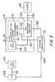
- a first system embodiment is shown in a functional block diagram and includes transmitter (TX) 108 which drives transmitter coils (TX COILS) 110 over lines 112, a receiver 114, a system controller 76 and an alarm 116.
- Receiver 114 includes receiver coils 118 (RX COILS), the outputs of which are furnished over lines 12, 14 and 16 to unit 10 (PER RX COIL NOISE ENVIRONMENT ANALYZER), discussed above, and over lines 122 to tag return processing circuitry 124 (RX PROCESSING CIRCUITRY), which controls alarm 116 over lines 126.
- Analyzer 10 controls receiver amplifier gain by its signals on its multiplexer output line 78, as above discussed.
- System controller 76 has connection with transmitter 108, analyzer 10 and processing circuitry 124 respectively over lines 128, 130 and 132.
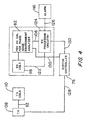
- Fig. 4 will seen to show a second system embodiment, which is identical with that of Fig. 3, except for its use of analyzer 82 whose multiplexer output line 106 controls receiver gain.
- the system of the invention under control of system controller 76 implements a frequency-hopping algorithm which allows it to better detect tags with a wider frequency distribution than the referenced commercial system.
- This frequency hopping takes place between two standard frequencies. These frequencies are 200Hz above and below the fundamental frequency of 58KHz.
- the system hops from one frequency to the other at every line sync (Phase A). Since the system can only process two input receiver coils in a single phase (its receiver is dual-channeled), it also hops between pairs of input coils or pedestals. This coil pair hopping takes place at 1.5 x the line frequency, on every second line phase.
- the system of frequency and coil pair hopping ensures that every coil input will be measured at each different frequency and each different phase of the power line for both transmit and noise phases.
- the system has an active mode, which has a transmit phase and a noise phase.
- the transmit phase includes a transmitting period (transmit window) and a receiving period (receive window).
- Transmit phase This is a phase of the power line during which the transmitter burst is enabled. Since tags respond to the transmitter by producing an in-band energy burst, this phase is used to determine if there is a hit, below defined.
- Signal-to-noise ratio The signal-to-noise ratio is the criterion used to verify a hit. This criterion is set in decibels (db).
- Validation sequence The validation sequence is a sequence of transmit and noise check phases, in number set by the user or otherwise by default, that the system uses to verify that current in-band energy is originating from a tag. If a validation sequence reaches completion, i.e., finds hits for each of the set number of sequences of transmit and noise check phases, the tag is verified and the system alarm will activate.
- Noise check phase is a particular type of noise phase that takes place only during validation sequences. It is used to verify that an energy source causing in-band responses in transmit phases, is not also present in the same amplitude during noise phases. If the source is present for both, it is considered a continuous wave, unrelated to tag responses, and is ignored by the system.
- Noise phase is a phase of the power mains during which the transmitter burst is disabled and is used to determine and record ambient noise levels for each receive coil in each phase.
- a hit takes place when the ratio between the instantaneous measurement in a transmit phase of in-band energy and the average value of the noise environment is equal to or greater than the user specified signal-to-noise criterion.
- the system contemplates a user to set the SNR in db and offers a default of 12db in the absence of user specified SNR criterion.
- the hit phase is a phase during which the first hit of a validation sequence took place.
- Deactivated tag check phase During the next-to-last transmit burst of a validation sequence, the system switches its transmit and receive frequency to a frequency common to deactivated tags. During this transmit phase, the in-band measurement must fall below the preceding normal frequency transmit phase measurement by a determined amount in order for the validation sequence to continue. If this is not the case, the energy being measured is considered by the system to have come from a deactivated label and the validation sequence is terminated. If this is the case, practice is to return to the validation sequence for the last transmit burst of the validation sequence.
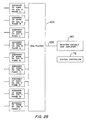
- Fig. 5 it shows a flow chart for a noise phase which is implemented by a microprocessor of system controller 76 with use of the Fig. 2A-2C type of noise environment analyzer.
- the microprocessor provides suitable timing for operation of scanner 84 and for the various storing and noise average computing operations of the circuitry of channels 86-102 and also controls the operation of multiplexer 104.
- step S1 NOISE PHASE.
- step S2 SCAN RECEIVING COILS FOR NOISE LEVELS PER PHASE, the returns from all participating coils are examined for each phase of the power mains.
- step S3 STORE CURRENT NOISE LEVELS WITH PAST NOISE LEVELS, the noise per coil per phase is accumulated.
- step S4 OBTAIN AVERAGE OF STORED NOISE LEVELS PER COIL PER PHASE, the average computation is made per coil per phase.
- Step S5 RETURN TO ACTIVE MODE, is the end of the noise phase.
- system controller 76 coordinates operation of multiplexer 104 such that the receiver gain is set correspondingly in the receive window of the transmit phase with the particular coil and phase providing the signal being processed for a hit.
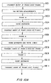
- Fig. 6 it shows a flow chart for a transmit phase which is implemented by the microprocessor of system controller 76 with use of the hardware of the Fig. 4 EAS system.
- the microprocessor provides suitable timing for operation of such hardware, particularly the timing of transmitter and receiver operation and the reading out of average noise computed by the noise environment analyzer as above referred to for receiver gain control.
- step S6 TRANSMIT PHASE.
- step S7 MEASURE INSTANTANEOUS COIL SIGNAL
- step S8 ? RATIO OF INSTANTANEOUS COIL SIGNAL TO NOISE AVERAGE ⁇ USER SET SNR, inquiry is made as to whether the receiving coil signal level is greater than or equal to the user set signal-to-noise ratio.
- step S9 ENTER VALSEQ, whereby progress is to the validation sequence, discussed below. If the answer to the step S8 inquiry is in the negative (N), progress is to step S10, RETURN TO ACTIVE MODE.
- step S11 VALSEQ.
- the validation sequence looks to hit phases which are also transmit phases for tag validation.
- Non-hit, non-transmit phases are noise phases.
- This aspect of the invention is realized in the outset steps of VALSEQ, as follows.
- step S13 ? HIT PHASE, inquiry is made as to whether the system is in the hit phase. If the response to the inquiry is negative, progress, as indicated by literals AA in Fig. 7A and in Fig. 7B, is to step S14, ? TRANSMIT PHASE. If the inquiry is answered in the affirmative, the system calls for a return, as indicated by the literals AB in Fig. 7A and Fig. 7B, to step S13. If the inquiry is answered in the negative, the system calls for the phase to be a noise phase, entering step S15, NOISE ENVIRONMENT ANALYZER, where noise averaging is updated and then return is made to step S13.
- step S13 inquiry is answered in the affirmative, progress is to step S16, ? TRANSMIT PHASE, where inquiry is made as to whether the current phase is a transmit phase. If the answer to the step S16 inquiry is in the negative, progress, as indicated by the literals AD in Figs. 7A and 7C, is to step S17, NOISE ENVIRONMENT ANALYZER, where noise averaging is updated and then progress is to step S18, ? PASS NOISE CHECK, where the system looks for the continuous wave occurrence present in both noise and transmit phases. If the answer to the step S18 is in the negative, progress is to step S19, RETURN TO ACTIVE MODE.
- step S18 progress is to step S13, as indicated by the literals AE in Figs. 7A and 7C.
- step S20 inquiry If the answer to the step S20 inquiry is affirmatively answered, i.e., the penultimate cycle of VALSEQ has been reached and N becomes equal to P-1, progress, per literals AH in Figs. 7A and 7C, is to step S24, ? DEACTIVATED TAG, where the system checks to determine whether the tag return being processed is from a deactivated tag.
- step S24 the system shifts to a frequency common to deactivated tags and the in-band measurement must fall below the preceding normal frequency transmit phase measurement by a determined amount in order for the validation sequence to continue. If this is not the case, the energy being measured is considered by the system to have come from a deactivated tag and step S24 is answered in the affirmative.
- the validation sequence is terminated, progress being to step S19, RETURN TO ACTIVE MODE. If this is the case, i.e., the tag is not a deactivated tag, progress is to step S23 to increment N and to return to step S13 for the validation sequence to enter the last cycle thereof.
- step S22 As step S22 is again reached, it is now answered in the negative, N being equal to P, and progress is to step S25, ACTIVATE ALARM.
- the system turns off the transmitter since looking for tags is not a concern until the alarm stops. Having the transmitter off during alarms provides the system with the opportunity to quickly update all noise averages for all receiver coils since every phase is now a noise phase. During this period, coil pair switching will take place at 180Hz. This ensures that all the averages will be current as soon as the alarm stops, even if a tag was close enough to the coils to start driving the averages up before the alarm took place.
- VALSEQ of Figs. 7A-C operates with a fixed value for P
- the invention contemplates setting the value of P adaptively to environmental noise.
- the SNR is set to 12 db and the number of hits is set to 4. If the first hit is 20db above the noise average, then the validation sequence continues with 4 hits required for an alarm. However, if the first hit is only 13db above the noise average, then the algorithm may add several hits to the number required for an alarm.
- the thresholds and number of added hits used in the validation sequence extension practice is handled by the system and is transparent to the user.
- step S27 the system examines whether the return, although qualifying for a validation sequence, does not have at least an SNR of X, e.g., the above example of 20db vs. a datum of 12db. If the inquiry is answered in the negative, i.e., the ratio exceeds or is equal to X, then progress is to S22 over AK lines of Figs. 8 and 7C, the same step to which line AG led.
- SNR SNR
- step S27 inquiry indicates the SNR to be less than X, e.g., the above example of 13db vs. the datum of 12db
- Progress is then to S22 again over lines AK of Figs. 8 and 7C.
- the routine of Fig. 9, entered from broken line AJ of Fig. 7A differs, calling for practice of the inquiry of step S27 for each cycle of VALSEQ.
- the Fig. 9 routine omits step S26 and opens directly with step S29, ? RATIO OF HIT TO NOISE AVERAGE ⁇ X. If the ratio is adequate, progress is over lines AK of Figs. 9 and 7C to step S22, i.e., VALSEQ is practiced with no change in P.
- the modified VALSEQ of Fig. 9 may be practiced for a given number of cycles thereof, rather than for each cycle.
- the thresholds and number of added hits used in the validation sequence extension practice are handled by the system and are transparent to the user.
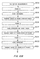
- FIG. 10A - 10C A series of system events (SE) for a successful validation sequence for four hits is shown in Figs. 10A - 10C.
- SE system events
- the example follows the VALSEQ routine of Figs. 7A-7C, without lines AI or AJ, i.e., P is 4 and is not expanded by the routines of Figs. 8 or 9.
- SE3 PHASE B is a non-hit, non-transmit phase.
- the system treats the time period as a noise phase, and NOISE AVERAGING occurs in SE4.
- TRANSMIT BURST AT PHASE C (NON-HIT PHASE)
- a transmit phase per system timing above discussed but is not the hit phase A. Accordingly, per step S14 of Fig.7B, the system does not look to noise averaging in the period.
- SE6 PHASE A is the hit phase but non-transmitting and SE7, NOISE AVERAGING AND NOISE CHECK, accordingly occurs.
- TRANSMIT BURST AT PHASE B (NON-HIT PHASE) is a transmit phase and noise averaging is accordingly not updated during the time period thereof.
- SE9, PHASE C is a non-hit, non-transmit phase and SE10, NOISE AVERAGING, occurs.
- SE11 TRANSMIT BURST AT PHASE A (HIT PHASE), is a second hit phase-transmit phase and return signals are processed in SE12, TAG RETURN MEASUREMENTS.
- SE13, PHASE B, is a non-hit, non-transmit phase and SE14, NOISE AVERAGING, occurs.
- TRANSMIT BURST AT PHASE C (NON-HIT PHASE) is another transmit phase and noise averaging is accordingly not updated during the time period thereof.
- SE16 PHASE A is a non-transmit hit phase and SE17, NOISE AVERAGING AND NOISE CHECK, is practiced.
- TRANSMIT BURST AT PHASE B (NON-HIT PHASE)
- noise averaging is accordingly not updated during the time period thereof.
- SE19, PHASE C is a non-hit, non-transmit phase and leads to SE20, NOISE AVERAGING.
- SE21 TRANSMIT BURST AT PHASE A (HIT PHASE), is a third hit phase-transmit phase and leads to SE22, DEACTIVATED TAG CHECK.
- SE23, PHASE B is a non-hit, non-transmit phase and leads to SE24, NOISE AVERAGING.
- TRANSMIT BURST AT PHASE C (NON-HIT PHASE) is a transmit phase and noise averaging is accordingly not updated.
- SE26 PHASE A
- SE27 NOISE AVERAGING AND NOISE CHECK.
- TRANSMIT BURST AT PHASE B (NON-HIT PHASE) is a transmit phase and noise averaging is accordingly not updated.
- SE29, PHASE C is a non-hit, non-transmit phase, leading to SE30, NOISE AVERAGING.
- SE30 TRANSMIT BURST AT PHASE A (HIT PHASE), is the fourth hit phase-transmit phase, leading to SE31, TAG RETURN MEASUREMENTS.
- the hit number for verification for the example is seen as four and deactivated tag checking is conducted in the penultimate cycle, i.e., the third hit-phase transmit phase.
- the invention will be seen to provide, in combination, in an electrical article surveillance system, a plurality of receiving coils and a noise environment analyzer including circuitry for determining the noise environment individual to each of the receiving coils.
- the noise environment analyzer includes scanning circuitry for individually connecting the receiving coils thereto and has separate noise analysis channels respectively for each receiving coil.
- the noise environment analyzer further includes in each channel thereof first circuitry for individual storing of signals received by the receiving coils, second circuitry for cumulative storage of signals stored by the first circuitry and third circuitry for,averaging the signals stored by the second circuitry.
- the noise environmental analyzer further includes multiplexer circuitry for receiving the output signals of the comparator circuitry and for providing output signals selectively indicative of the averaged noise signals.
- the system transmitter may be powered from a multi-phase power source.
- the noise environment analyzer further includes separate noise analysis channels respectively for each the receiving coil and for each phase of the multi-phase power source means.
- the noise analysis channels are arranged in groups corresponding in number to the number of receiving coils and each noise analysis channel group comprises channels in number corresponding to the number of phases of the multi-phase power source.
- the invention provides a system comprising a transmitter operable for generating a magnetic field in a surveillance area and a receiver having a plurality of receiving coils and noise environment analysis circuitry operable for determining the noise environment individual to each of the receiving coils.
- the system further includes control circuitry (1) for establishing a succession of transmit and non-transmit phases, the transmit phases having a transmit window and a receive window, (2) for operating the transmitter means during the transmit phases and (3) for operating the noise environment analyzer during the non-transmit (noise) phases.
- the control circuitry operates the receiver, upon receiver detection of an electronic article surveillance tag, to implement a validation sequence on a succession of signals received by the receiving coil which provided the signal giving rise to the detection.
- the control circuitry operates the transmitter means in one cycle of the validation sequence to transmit energy at a frequency at which a deactivated electronic article surveillance tag is resonant.
- the invention provides a system comprising a transmitter operable for generating a magnetic field in a surveillance area, a receiver having a plurality of receiving coils and operable, upon detection of an electronic article surveillance tag, to implement a validation sequence on a succession of signals received by the receiving coil which provided the signal giving rise to the detection and control circuitry for operating the transmitter means and the receiver means, the control circuitry having facility for varying the number of cycles in the validation sequence.
- control circuitry establishes the number of cycles in the validation sequence adaptively to the noise environment of the receiving coil which provided the signal giving rise to the detection.
- the control circuitry sets a datum number of cycles in the validation sequence and increases the number of cycles above the datum number adaptively to the noise environment of the receiving coil which provided the signal giving rise to the detection.
- the control circuitry establishes a predetermined signal-to-noise ratio for a tag detection warranting initiation of the validation sequence and increases the number of cycles above the datum number upon actual received signal-to-noise ratio of the receiving coil which provided the signal giving rise to the detection having a preselected relation to the predetermined signal-to-noise ratio.
- the invention provides a transmitter operable at a fundamental frequency for generating a magnetic field in a surveillance area, a receiver for detection of electronic article surveillance tags and control circuitry for operating the transmitter with a frequency hopping between frequencies respective above and below the fundamental frequency.
- the transmitter is powered from a multi-phase supply and the control circuitry effects the frequency hopping at every occurrence of an exclusive one of the phases of the multi-phase supply.
- the system may selectively skip transmit phases and use the time for noise checking to enhance system performance.
- the deactivated tag check has been described as practiced in the penultimate step of VALSEQ, it may be placed in any desired cycle of VALSEQ. These variations may be altered dynamically, as desired. Accordingly, it is to be understood that the particularly disclosed and depicted embodiments are intended in an illustrative and not in a limiting sense. The scope of the invention are set forth in the following claims.
Landscapes
- Engineering & Computer Science (AREA)
- Physics & Mathematics (AREA)
- Signal Processing (AREA)
- Automation & Control Theory (AREA)
- Computer Security & Cryptography (AREA)
- Electromagnetism (AREA)
- General Physics & Mathematics (AREA)
- Burglar Alarm Systems (AREA)
Claims (28)
- Système de surveillance électronique d'articles du type comprenant un moyen d'émetteur (108, 100, 112) pouvant être mis en oeuvre en vue de générer un champ magnétique dans une zone de surveillance et un moyen de récepteur comportant une pluralité de bobines (118), caractérisé en ce que ledit système comprend un moyen d'analyse d'environnement de bruit (10) pouvant être mis en oeuvre en vue de déterminer l'environnement de bruit individuel à chacune desdites bobines de réception.
- Système selon la revendication 1, comprenant en outre un moyen de commande (76) destiné à établir une succession de phases d'émission et de non émission, chaque phase d'émission comportant une fenêtre d'émission et une fenêtre de réception, en vue de mettre en oeuvre ledit moyen d'émetteur durant lesdites phases d'émission et en vue de mettre en oeuvre ledit moyen d'analyse d'environnement de bruit durant lesdites phases.de non émission.
- Système selon la revendication 1 ou 2, dans lequel ledit moyen de commande met en oeuvre ledit récepteur, lors d'une détection par le récepteur d'une étiquette de surveillance électronique d'articles, afin de réaliser une séquence de validation sur une succession de signaux reçus par la bobine de réception qui a fourni le signal produisant ladite détection.
- Système selon la revendication 3, dans lequel ledit moyen de commande met en oeuvre ledit moyen d'émetteur dans un cycle de ladite séquence de validation afin d'émettre de l'énergie à une fréquence à laquelle une étiquette de surveillance électronique d'articles désactivée est résonnante.
- Système selon la revendication 4, dans lequel ledit moyen de commande établit le nombre de cycles dans ladite séquence de validation de façon adaptative à l'environnement de bruit déterminé par ledit moyen d'analyse d'environnement de bruit.
- Système selon la revendication 5, dans lequel ledit moyen de commande établit un nombre de cycles de référence dans ladite séquence de validation et augmente le nombre de cycles au-dessus dudit nombre de référence de façon adaptative à l'environnement de bruit déterminé par ledit moyen d'analyse d'environnement de bruit.
- Système selon la revendication 6, dans lequel ledit moyen de commande établit un rapport signal sur bruit prédéterminé en vue d'une détection d'étiquette garantissant le lancement de ladite séquence de validation et augmente le nombre de cycles au-dessus dudit nombre de référence lors d'un rapport signal sur bruit reçu réel présentant une relation présélectionnée par rapport audit rapport signal sur bruit prédéterminé.
- Système selon la revendication 1, dans lequel ledit moyen d'analyse d'environnement de bruit comprend un moyen de balayage (18) en vue de relier chacune desdites bobines de réception à celui-ci.
- Système selon la revendication 8, dans lequel ledit moyen d'analyse d'environnement de bruit comprend des canaux d'analyse de bruit séparés (22, 26 et 32 ; 40, 44 et 50 ; 58, 62 et 68) respectivement pour chaque dite bobine de réception.
- Système selon la revendication 9, dans lequel ledit moyen d'analyse d'environnement de bruit comprend en outre dans chaque dit canal un premier moyen (22 ; 40 ; 62) destiné à mémoriser individuellement des signaux reçus par lesdites bobines de réception.
- Système selon la revendication 10, dans lequel ledit moyen d'analyse d'environnement de bruit comprend en outre dans chaque dit canal un second moyen (26 ; 44 ; 62) en vue d'une mémorisation cumulative de signaux mémorisés par ledit premier moyen.
- Système selon la revendication 11, dans lequel ledit moyen d'analyse d'environnement de bruit comprend en outre dans chaque dit canal, un troisième moyen (32 ; 50 ; 68) en vue d'établir la moyenne des signaux mémorisés par ledit second moyen.
- Système selon la revendication 12, dans lequel ledit moyen d'analyse d'environnement de bruit comprend en outre un moyen de multiplexeur (74) destiné à recevoir les signaux de sortie dudit troisième moyen.
- Système selon la revendication 1, dans lequel ledit moyen d'émission est alimenté par un moyen de source d'alimentation à phases multiples et dans lequel ledit moyen d'analyse d'environnement de bruit comprend en outre les canaux d'analyse de bruit séparés (86 à 102) respectivement pour chaque dite bobine de réception et pour chaque phase dudit moyen de source d'alimentation à phases multiples.
- Système selon la revendication 14, dans lequel lesdits canaux d'analyse de bruit sont agencés en groupes (86 à 102) correspondant en nombre au nombre de bobines de réception et dans lequel chaque groupe de canaux d'analyse de bruit comprend des canaux en nombre correspondant au nombre de phases dudit moyen de source d'alimentation à phases multiples.
- Système selon la revendication 15, dans lequel chaque dit canal d'analyse de bruit comprend un premier moyen (22, 40 ; 62) destiné à mémoriser des signaux reçus par une bobine distincte parmi lesdites bobines de réception pour une phase distincte dudit moyen de source d'alimentation à phases multiples.
- Système selon la revendication 16, dans lequel chaque dit canal d'analyse de bruit comprend en outre un second moyen (26 ; 44 ; 62) en vue d'une mémorisation cumulative de signaux mémorisés par ledit premier moyen de celui-ci.
- Système selon la revendication 17, dans lequel chaque dit canal d'analyse de bruit comprend en outre un troisième moyen (32 ; 50 ; 68) destiné à établir la moyenne des signaux mémorisés par ledit second moyen de celui-ci.
- Système selon la revendication 18, dans lequel ledit moyen d'analyse d'environnement de bruit comprend en outre un moyen de multiplexeur (74) destiné à recevoir les signaux de sortie dudit troisième moyen.
- Système selon la revendication 1, dans lequel ledit moyen de réception peut être mis en oeuvre, lors de la détection d'une étiquette de surveillance électronique, afin de réaliser une séquence de validation sur une succession de signaux reçus par la bobine de réception qui a fourni le signal produisant ladite détection, ledit système comprenant en outre un moyen de commande (76) destiné à mettre en oeuvre ledit moyen d'émetteur et ledit moyen de récepteur, ledit moyen de commande ayant la possibilité de faire varier le nombre de cycles dans ladite séquence de validation.
- Système selon la revendication 20, dans lequel ledit moyen de commande établit le nombre de cycles dans ladite séquence de validation de façon adaptative à l'environnement de bruit de ladite bobine de réception qui a fourni le signal produisant ladite détection.
- Système selon la revendication 21, dans lequel ledit moyen de commande établit un nombre de cycles de référence dans ladite séquence de validation et augmente le nombre de cycles au-dessus dudit nombre de référence de façon adaptative à l'environnement de bruit de ladite bobine de réception qui a fourni le signal produisant ladite détection.
- Système selon la revendication 22, dans lequel ledit moyen de commande établit un rapport signal sur bruit prédéterminé en vue d'une détection d'étiquette garantissant le lancement de ladite séquence de validation et augmente le nombre de cycles au-dessus du nombre de référence lors d'un rapport signal sur bruit reçu réel de ladite bobine de réception qui a fourni le signal produisant ladite détection, présentant une relation présélectionnée par rapport audit rapport signal sur bruit prédéterminé.
- Système selon la revendication 20, dans lequel ledit récepteur comprend en outre un moyen d'analyse d'environnement de bruit pouvant être mis en oeuvre en vue de déterminer l'environnement de bruit individuel à chacune desdites bobines de réception.
- Système selon la revendication 20, dans lequel ledit moyen de commande met en oeuvre ledit récepteur, lors de la détection du récepteur d'une étiquette de surveillance électronique d'articles, afin de réaliser une séquence de validation sur une succession de signaux reçus par la bobine de réception qui a fourni le signal produisant ladite détection.
- Système selon la revendication 25, dans lequel ledit moyen de commande met en oeuvre ledit moyen d'émetteur dans un cycle de ladite séquence de validation afin d'émettre de l'énergie à une fréquence à laquelle une étiquette de surveillance électronique d'articles désactivée est résonante.
- Système selon la revendication 1, dans lequel ledit moyen d'émetteur est mis en oeuvre à une fréquence fondamentale lors de la génération dudit champ magnétique, ledit système comprenant en outre un moyen de commande destiné à mettre en oeuvre ledit moyen d'émetteur avec un saut de fréquence entre des fréquences respectivement supérieure et inférieure à ladite fréquence fondamentale.
- Système selon la revendication 27, dans lequel ledit moyen d'émetteur est alimenté à partir d'une alimentation à phases multiples et dans lequel ledit moyen de commande effectue ledit saut de fréquence à chaque occurrence d'une phase exclusive parmi les phases de ladite alimentation à phases multiples.
Applications Claiming Priority (2)
| Application Number | Priority Date | Filing Date | Title |
|---|---|---|---|
| US08/313,849 US5495229A (en) | 1994-09-28 | 1994-09-28 | Pulsed electronic article surveillance device employing expert system techniques for dynamic optimization |
| US313849 | 1994-09-28 |
Publications (2)
| Publication Number | Publication Date |
|---|---|
| EP0704830A1 EP0704830A1 (fr) | 1996-04-03 |
| EP0704830B1 true EP0704830B1 (fr) | 2002-07-03 |
Family
ID=23217408
Family Applications (1)
| Application Number | Title | Priority Date | Filing Date |
|---|---|---|---|
| EP95114177A Expired - Lifetime EP0704830B1 (fr) | 1994-09-28 | 1995-09-09 | Dispositif électronique impulsionnel de surveillance d'article utilisant les techniques de système expert pour l'optimisation dynamique |
Country Status (7)
| Country | Link |
|---|---|
| US (1) | US5495229A (fr) |
| EP (1) | EP0704830B1 (fr) |
| JP (1) | JPH08106583A (fr) |
| AU (1) | AU701366B2 (fr) |
| BR (1) | BR9504185A (fr) |
| CA (1) | CA2155156C (fr) |
| DE (1) | DE69527241T2 (fr) |
Families Citing this family (31)
| Publication number | Priority date | Publication date | Assignee | Title |
|---|---|---|---|---|
| US5627516A (en) * | 1994-09-28 | 1997-05-06 | Sensormatic Electronics Corporation | Electronic article surveillance input configuration control system employing expert system techniques for dynamic optimization |
| US5850181A (en) * | 1996-04-03 | 1998-12-15 | International Business Machines Corporation | Method of transporting radio frequency power to energize radio frequency identification transponders |
| US7511621B1 (en) | 1995-08-31 | 2009-03-31 | Intermec Ip Corp. | High-performance mobile power antennas |
| US5737241A (en) * | 1995-11-02 | 1998-04-07 | Sensormatic Electronics Corporation | User management interface for EAS system |
| US5699046A (en) * | 1995-11-02 | 1997-12-16 | Sensormatic Electronics Corporation | EAS system employing central and local stations with shared functions |
| FR2741980B1 (fr) * | 1995-12-01 | 1998-01-23 | Pierre Raimbault | Procede de mise en phase d'etiquettes electroniques station d'interrogation et etiquette electronique pour sa mise en oeuvre |
| EP0798681A1 (fr) * | 1996-03-29 | 1997-10-01 | Sensormatic Electronics Corporation | Signal d'interrogation d'impulsion dans un système de surveillance d'articles fréquences harmoniques |
| US6429775B1 (en) * | 1996-04-03 | 2002-08-06 | Intermec Ip Corp. | Apparatus for transporting radio frequency power to energize radio frequency identification transponders |
| DE19644927A1 (de) * | 1996-10-29 | 1998-04-30 | Esselte Meto Int Gmbh | Vorrichtung zur Überwachung eines elektronischen Sicherungselementes in einer Abfragezone |
| US5796339A (en) * | 1996-12-02 | 1998-08-18 | Sensormatic Electronics Corporation | Shoplifting detection label deactivator with combined excitation-deactivation coil |
| DE19650050A1 (de) * | 1996-12-03 | 1998-06-04 | Meto International Gmbh | Vorrichtung zur Überwachung von elektronischen Sicherungselementen |
| US5995002A (en) * | 1997-11-28 | 1999-11-30 | Sensormatic Electronics Corporation | Line synchronized delays for multiple pulsed EAS systems |
| US5909178A (en) * | 1997-11-28 | 1999-06-01 | Sensormatic Electronics Corporation | Signal detection in high noise environments |
| US6118378A (en) * | 1997-11-28 | 2000-09-12 | Sensormatic Electronics Corporation | Pulsed magnetic EAS system incorporating single antenna with independent phasing |
| US5969659A (en) * | 1997-11-28 | 1999-10-19 | Sensormatic Electronics Corporation | Analog to digital converters with extended dynamic range |
| US6188310B1 (en) | 1997-11-28 | 2001-02-13 | Sensormatic Electronics Corporation | Natural frequency measurement of magnetic markers |
| FR2787654A1 (fr) * | 1998-12-21 | 2000-06-23 | Valeo Securite Habitacle | Dispositif de communication basse frequence par couplage magnetique |
| US6249229B1 (en) * | 1999-08-16 | 2001-06-19 | Checkpoint Systems, Inc., A Corp. Of Pennsylvania | Electronic article security system employing variable time shifts |
| US6597744B1 (en) * | 1999-08-23 | 2003-07-22 | Sensormatic Electronics Corporation | Transmitter for electronic article surveillance system |
| US6693511B1 (en) | 1999-09-24 | 2004-02-17 | Ge Interlogix, Inc. | System and method for communicating with dormant radio frequency identification tags |
| US6452504B1 (en) * | 1999-09-24 | 2002-09-17 | Ge Interlogix, Inc. | System and method for communication with radio frequency identification tags using tow message DFM protocol |
| US6447294B1 (en) | 1999-12-13 | 2002-09-10 | William Raymond Price | Locator for lost dentures |
| US7518532B2 (en) * | 2005-05-26 | 2009-04-14 | Tc License Ltd. | Intermodulation mitigation technique in an RFID system |
| US8786439B2 (en) * | 2005-09-02 | 2014-07-22 | Wg Security Products | Active antenna |
| US7482926B2 (en) * | 2005-10-28 | 2009-01-27 | Intermec Ip Corp. | System and method of enhancing range in a radio frequency identification system |
| US7665012B2 (en) * | 2005-11-04 | 2010-02-16 | At&T Intellectual Property I, Lp | Impulse noise mitigation |
| EP2038680A1 (fr) * | 2006-06-19 | 2009-03-25 | Minelab Electronics PTY LTD | Détecteur de métaux avec capacités de détection améliorées |
| JP4206108B2 (ja) * | 2006-07-28 | 2009-01-07 | 東芝テック株式会社 | 無線タグリーダライタ |
| US7852197B2 (en) * | 2007-06-08 | 2010-12-14 | Sensomatic Electronics, LLC | System and method for inhibiting detection of deactivated labels using detection filters having an adaptive threshold |
| US8633821B2 (en) * | 2007-12-03 | 2014-01-21 | Avery Dennison Corporation | Dual use RFID/EAS device |
| US9595177B2 (en) | 2014-12-14 | 2017-03-14 | Wg Security Products, Inc. | Noise compensating EAS antenna system |
Family Cites Families (6)
| Publication number | Priority date | Publication date | Assignee | Title |
|---|---|---|---|---|
| CA1234892A (fr) * | 1984-02-16 | 1988-04-05 | Pierre Taillefer | Systeme de detection pour etiquettes anti-vol |
| US4658241A (en) * | 1985-09-17 | 1987-04-14 | Allied Corporation | Surveillance system including transmitter and receiver synchronized by power line zero crossings |
| US4720701A (en) * | 1986-01-02 | 1988-01-19 | Lichtblau G J | System with enhanced signal detection and discrimination with saturable magnetic marker |
| US5023598A (en) * | 1990-01-02 | 1991-06-11 | Pitney Bowes Inc. | Digital signal processor for electronic article gates |
| EP0561062A1 (fr) * | 1992-03-17 | 1993-09-22 | Moisei Samuel Granovsky | Méthode et système électromagnétique de sécurité pour protéger des objets surveillés dans une zone de surveillance |
| US5349332A (en) * | 1992-10-13 | 1994-09-20 | Sensormatic Electronics Corportion | EAS system with requency hopping |
-
1994
- 1994-09-28 US US08/313,849 patent/US5495229A/en not_active Expired - Lifetime
-
1995
- 1995-08-01 CA CA002155156A patent/CA2155156C/fr not_active Expired - Fee Related
- 1995-09-09 DE DE69527241T patent/DE69527241T2/de not_active Expired - Fee Related
- 1995-09-09 EP EP95114177A patent/EP0704830B1/fr not_active Expired - Lifetime
- 1995-09-27 BR BR9504185A patent/BR9504185A/pt not_active Application Discontinuation
- 1995-09-27 AU AU32932/95A patent/AU701366B2/en not_active Ceased
- 1995-09-27 JP JP7273626A patent/JPH08106583A/ja active Pending
Also Published As
| Publication number | Publication date |
|---|---|
| US5495229A (en) | 1996-02-27 |
| AU701366B2 (en) | 1999-01-28 |
| CA2155156A1 (fr) | 1996-03-29 |
| DE69527241T2 (de) | 2002-11-14 |
| BR9504185A (pt) | 1996-07-30 |
| DE69527241D1 (de) | 2002-08-08 |
| JPH08106583A (ja) | 1996-04-23 |
| AU3293295A (en) | 1996-04-18 |
| EP0704830A1 (fr) | 1996-04-03 |
| CA2155156C (fr) | 2006-06-06 |
Similar Documents
| Publication | Publication Date | Title |
|---|---|---|
| EP0704830B1 (fr) | Dispositif électronique impulsionnel de surveillance d'article utilisant les techniques de système expert pour l'optimisation dynamique | |
| US5353011A (en) | Electronic article security system with digital signal processing and increased detection range | |
| EP0704829B1 (fr) | Système de commande d'entrées de récepteur d'un système électronique de surveillance d'articles à optimisation dynamique utilisant un système expert | |
| US5955950A (en) | Low noise signal generator for use with an RFID system | |
| EP0696783B1 (fr) | Système électronique de surveillance d'articles avec capacité de déactivation d'étiquettes | |
| EP2524360B1 (fr) | Procédé et système d'extinction au récepteur à l'aide de signaux d'émission cohérents | |
| KR101744898B1 (ko) | 통합형 금속 검출/전자식 물품 감시 시스템들에서 간섭의 효과를 감소시키기 위한 방법 및 시스템 | |
| AU1867195A (en) | Metal detection system | |
| EP0646266B1 (fr) | Systeme de detection de vol faisant appel au traitement de signaux numeriques | |
| EP1290655B1 (fr) | Systeme electronique de surveillance d'articles a couverture de sortie etendue et a depassement reduit | |
| AU2001259460A1 (en) | EAS system with wide exit coverage and reduced over-range | |
| AU716217B2 (en) | Pulsed electronic article surveillance device employing expert system techniques for dynamic optimization | |
| CN1096049C (zh) | 具有梳状滤波和误报警抑制的电子物品监视系统 | |
| AU711993B2 (en) | Electronic article surveillance system with comb filtering by polyphase decomposition and nonlinear filtering of subsequences | |
| AU2010341820B2 (en) | Method and system for receiver nulling using coherent transmit signals | |
| JPH0676185A (ja) | 電子的警備システム用個別給電多重ループアンテナ | |
| SE9601358L (sv) | Förfarande och anordning för deaktivering av larmelement |
Legal Events
| Date | Code | Title | Description |
|---|---|---|---|
| PUAI | Public reference made under article 153(3) epc to a published international application that has entered the european phase |
Free format text: ORIGINAL CODE: 0009012 |
|
| AK | Designated contracting states |
Kind code of ref document: A1 Designated state(s): DE FR GB SE |
|
| 17P | Request for examination filed |
Effective date: 19960725 |
|
| 17Q | First examination report despatched |
Effective date: 19980710 |
|
| GRAG | Despatch of communication of intention to grant |
Free format text: ORIGINAL CODE: EPIDOS AGRA |
|
| GRAG | Despatch of communication of intention to grant |
Free format text: ORIGINAL CODE: EPIDOS AGRA |
|
| GRAH | Despatch of communication of intention to grant a patent |
Free format text: ORIGINAL CODE: EPIDOS IGRA |
|
| GRAH | Despatch of communication of intention to grant a patent |
Free format text: ORIGINAL CODE: EPIDOS IGRA |
|
| GRAA | (expected) grant |
Free format text: ORIGINAL CODE: 0009210 |
|
| AK | Designated contracting states |
Kind code of ref document: B1 Designated state(s): DE FR GB SE |
|
| REF | Corresponds to: |
Ref document number: 69527241 Country of ref document: DE Date of ref document: 20020808 |
|
| PG25 | Lapsed in a contracting state [announced via postgrant information from national office to epo] |
Ref country code: SE Free format text: LAPSE BECAUSE OF FAILURE TO SUBMIT A TRANSLATION OF THE DESCRIPTION OR TO PAY THE FEE WITHIN THE PRESCRIBED TIME-LIMIT Effective date: 20021003 |
|
| ET | Fr: translation filed | ||
| PLBE | No opposition filed within time limit |
Free format text: ORIGINAL CODE: 0009261 |
|
| STAA | Information on the status of an ep patent application or granted ep patent |
Free format text: STATUS: NO OPPOSITION FILED WITHIN TIME LIMIT |
|
| 26N | No opposition filed |
Effective date: 20030404 |
|
| REG | Reference to a national code |
Ref country code: FR Ref legal event code: CA |
|
| REG | Reference to a national code |
Ref country code: GB Ref legal event code: 732E |
|
| PGFP | Annual fee paid to national office [announced via postgrant information from national office to epo] |
Ref country code: DE Payment date: 20071031 Year of fee payment: 13 |
|
| PG25 | Lapsed in a contracting state [announced via postgrant information from national office to epo] |
Ref country code: DE Free format text: LAPSE BECAUSE OF NON-PAYMENT OF DUE FEES Effective date: 20090401 |
|
| REG | Reference to a national code |
Ref country code: GB Ref legal event code: 732E Free format text: REGISTERED BETWEEN 20101111 AND 20101117 |
|
| REG | Reference to a national code |
Ref country code: FR Ref legal event code: TP Owner name: SENSORMATIC ELECTRONICS, LLC, US Effective date: 20110913 |
|
| PGFP | Annual fee paid to national office [announced via postgrant information from national office to epo] |
Ref country code: FR Payment date: 20111005 Year of fee payment: 17 Ref country code: GB Payment date: 20110926 Year of fee payment: 17 |
|
| GBPC | Gb: european patent ceased through non-payment of renewal fee |
Effective date: 20120909 |
|
| REG | Reference to a national code |
Ref country code: FR Ref legal event code: ST Effective date: 20130531 |
|
| PG25 | Lapsed in a contracting state [announced via postgrant information from national office to epo] |
Ref country code: GB Free format text: LAPSE BECAUSE OF NON-PAYMENT OF DUE FEES Effective date: 20120909 |
|
| PG25 | Lapsed in a contracting state [announced via postgrant information from national office to epo] |
Ref country code: FR Free format text: LAPSE BECAUSE OF NON-PAYMENT OF DUE FEES Effective date: 20121001 |