EP0561062A1 - Méthode et système électromagnétique de sécurité pour protéger des objets surveillés dans une zone de surveillance - Google Patents
Méthode et système électromagnétique de sécurité pour protéger des objets surveillés dans une zone de surveillance Download PDFInfo
- Publication number
- EP0561062A1 EP0561062A1 EP92200765A EP92200765A EP0561062A1 EP 0561062 A1 EP0561062 A1 EP 0561062A1 EP 92200765 A EP92200765 A EP 92200765A EP 92200765 A EP92200765 A EP 92200765A EP 0561062 A1 EP0561062 A1 EP 0561062A1
- Authority
- EP
- European Patent Office
- Prior art keywords
- windows
- window
- signal
- signals
- cycle
- Prior art date
- Legal status (The legal status is an assumption and is not a legal conclusion. Google has not performed a legal analysis and makes no representation as to the accuracy of the status listed.)
- Withdrawn
Links
Images


Classifications
-
- G—PHYSICS
- G08—SIGNALLING
- G08B—SIGNALLING OR CALLING SYSTEMS; ORDER TELEGRAPHS; ALARM SYSTEMS
- G08B13/00—Burglar, theft or intruder alarms
- G08B13/22—Electrical actuation
- G08B13/24—Electrical actuation by interference with electromagnetic field distribution
- G08B13/2402—Electronic Article Surveillance [EAS], i.e. systems using tags for detecting removal of a tagged item from a secure area, e.g. tags for detecting shoplifting
- G08B13/2405—Electronic Article Surveillance [EAS], i.e. systems using tags for detecting removal of a tagged item from a secure area, e.g. tags for detecting shoplifting characterised by the tag technology used
- G08B13/2408—Electronic Article Surveillance [EAS], i.e. systems using tags for detecting removal of a tagged item from a secure area, e.g. tags for detecting shoplifting characterised by the tag technology used using ferromagnetic tags
-
- G—PHYSICS
- G08—SIGNALLING
- G08B—SIGNALLING OR CALLING SYSTEMS; ORDER TELEGRAPHS; ALARM SYSTEMS
- G08B13/00—Burglar, theft or intruder alarms
- G08B13/22—Electrical actuation
- G08B13/24—Electrical actuation by interference with electromagnetic field distribution
- G08B13/2402—Electronic Article Surveillance [EAS], i.e. systems using tags for detecting removal of a tagged item from a secure area, e.g. tags for detecting shoplifting
- G08B13/2465—Aspects related to the EAS system, e.g. system components other than tags
- G08B13/2468—Antenna in system and the related signal processing
- G08B13/2471—Antenna signal processing by receiver or emitter
-
- G—PHYSICS
- G08—SIGNALLING
- G08B—SIGNALLING OR CALLING SYSTEMS; ORDER TELEGRAPHS; ALARM SYSTEMS
- G08B13/00—Burglar, theft or intruder alarms
- G08B13/22—Electrical actuation
- G08B13/24—Electrical actuation by interference with electromagnetic field distribution
- G08B13/2402—Electronic Article Surveillance [EAS], i.e. systems using tags for detecting removal of a tagged item from a secure area, e.g. tags for detecting shoplifting
- G08B13/2465—Aspects related to the EAS system, e.g. system components other than tags
- G08B13/2468—Antenna in system and the related signal processing
- G08B13/2477—Antenna or antenna activator circuit
-
- G—PHYSICS
- G08—SIGNALLING
- G08B—SIGNALLING OR CALLING SYSTEMS; ORDER TELEGRAPHS; ALARM SYSTEMS
- G08B13/00—Burglar, theft or intruder alarms
- G08B13/22—Electrical actuation
- G08B13/24—Electrical actuation by interference with electromagnetic field distribution
- G08B13/2402—Electronic Article Surveillance [EAS], i.e. systems using tags for detecting removal of a tagged item from a secure area, e.g. tags for detecting shoplifting
- G08B13/2465—Aspects related to the EAS system, e.g. system components other than tags
- G08B13/2488—Timing issues, e.g. synchronising measures to avoid signal collision, with multiple emitters or a single emitter and receiver
Definitions
- This invention relates to the detection of objects in a surveillance zone and more particularly to a method and apparatus for the reliable detection of a tag made of soft magnetic material (with a very narrow hysteresis loop) and attached to the object, unauthorized removal of which has to be prevented, through an oscillatory electromagnetic field within the surveillance zone.
- the "frequency-domain” systems have to use a continuous transmission of the interrogation field in order to obtain detectable magnitudes of the harmonics of a tag signal. But it is possible to utilize a continuous transmission in so called “time domain” systems which are concerned with the shape of a signal rather than with the frequency content of same.
- US patent No. 4,623,877 describes such a "time-domain” system with continuous transmission. This known system uses a bias provided by the earth magnetic field to the interrogation field which results in an asymmetry in the positions of tag signals with regard to periodically repeated predetermined points of the interrogation field. According to US-A-4,623,877 any other magnetic but not so easily saturated material can produce field disturbance signals at the points where the field is much stronger and therefore those signals will be more symmetric.
- US-A-4,623,877 also provides periodic blanking of the signal processor at the time intervals corresponding to the amplitude levels of the field in order to ignore signals from metal objects originated in a strong field. But when placed close to one of the transmitting antennae, where the strength of the field is really high and the bias of the earth magnetic field is almost negligible, the tag signals will have a good symmetry and thus may be ignored, whereas the metal objects will be saturated at a much lower level than the amplitude level of the alternating field, thus producing asymmetric signals within the time windows and therefore initiating a false alarm. Also the earth magnetic field is very weak in the areas close to the equator, so this known system will not be efficient if installed in many countries of Latin America or Africa or even the Middle East. Also, periodic external noise asynchronous to the interrogation field (from video monitors, for example) can produce a sensible level of asymmetry and cause a false alarm unless long averaging is used, which makes the system slow.
- the prior art systems with pulsing transmission are related to the time-domain group.
- these systems use either a comparison of the wave shape of the distortion signal to stored different samples of possible wave shapes (as disclosed in US patent No. 4,663,612), or (as proposed in US patent No. 4,527,152) decide about the presence of a tag signal by measuring the width of a pulse in the time-window, or by the use of cross-correlation between a stored signal and a repeated one in order to establish how similar they are. All these methods provide neither adequate reliability of signal recognition nor protection against false alarms.
- the method of pulse width measurement can cause severe false alarming in a noisy environment, and cross-correlation methods are totally helpless against a succession of identical spurious signals originated either by metal objects in the interrogation field or induced by external periodic fields from, for example, horizontal deflection units of video monitors.
- the invention provides a method and apparatus to modify and standardize differently shaped original tag signals so that synchronous detection methods can be used for reliable recovery of a modified tag signal from noise.
- This invention further provides a method and apparatus using a predetermined reduction of the field strength at certain moments of the transmission for the reliable separation of true signals from those originated by metal objects.
- Another aspect of the invention provides a method and means to suppress a periodic external noise with a known repetition rate within the time windows.
- a method is provided utilizing a choice of moment(s) to start certain pulse(s) of transmission in order to reject periodic noises with unknown frequencies.
- a suitable apparatus embodying this method is provided, too.
- the invention also provides a method and means for a cyclic evaluation of the external noise using time periods which occur following the termination of every pulse of transmission.
- the noise evaluation is used in the present invention as a dynamic threshold, which fully prevents false alarms due to any noise unrelated to the interrogation field.
- Another aspect of the invention provides a method and the means for cyclic redistribution of the spatial orientation of the field. According to the method, during every second cycle, both transmitting antennae transmit their oscillatory pulses simultaneously and in anti-phase, whereas in between these cycles only one of these two antennae transmits in turn.
- Fig. 1 is a block diagram of an example of a security system according to the present invention.
- Figs. 2a and 2b illustrate two basic "master-slave" configurations for the synchronization of two or more systems.
- Fig. 3 is a detailed block diagram of a preferred embodiment of a transmitter suitable for use in a system according to the present invention.
- Fig. 4 is a time diagram illustrating signals controlling the transmitter and a current in the transmitting antenna.
- Fig. 5 illustrates a method of energizing two transmitters in order that they transmit their fields in opposite phases.
- Fig. 6 is a block diagram of a preferred embodiment of the receiver according to the invention.
- Fig. 7 shows spectra of differently shaped original tag signals.
- Fig. 8 illustrates a method of modification of the tag signals according to the present invention.
- Fig. 9 shows a tag signal modified according to the method of the invention.
- Fig. 10 is a time diagram illustrating different signals originated in the interrogation field and also explaining the positions of the time-windows according to the present invention.
- Fig. 11 is a time diagram showing a minimal set of controller commands in the signal processor according to the invention.
- Fig. 12 is a block diagram of a synchronous detector as used in a preferred embodiment of the invention.
- Fig. 13 shows in a block-diagrammatical form a preferred embodiment of the magnitude extractor.
- Figs. 14 and 15 illustrate, in a time-digrammatical form, a method of suppressing periodic noises according to the present invention.
- Fig. 16 is a time diagram explaining the use of two overlapping windows for the evaluation of the noise.
- Figs. 17 and 18 are two parts of a block diagram of a signal processor used in a preferred embodiment of the present invention.
- Fig. 1 shows the block diagram of a preferred embodiment of a security system according to the present invention.
- the system comprises two gates (or passageways) 1 and 2 which illustrates the possible way to expand the system.
- a minimal system with only one security gate is fully representative of the present invention. Therefore, the system, where possible, will be described in its elementary form, containing only one gate (1 for example).
- This gate is defined by two identical panels comprising at least one pair of transmitting antennae 3 and 4 and a corresponding pair of receiving antennae 6 and 7.
- the transmitting antennae 3 and 4 are connected to terminals A1,B1 and A2,B2 of transmitters T x1 (9) and T x2 (10) respectively.
- These transmitters are operated in accordance with commands 12 and 13 from a controller Cr (14), and use their antennae 3 and 4 to produce an electromagnetic interrogation field H alternating with frequency fo, in the surveillance zone 1.
- This field is able to drive the soft (i.e. having a narrow hysteresis loop) magnetic material which is provided in a security tag for use with a system according to the present invention, alternatively from one magnetically saturated state to another.
- the system is able to work successfully with any soft magnetic materials, once the following two conditions are met: the tag material should have a rather narrow and fairly square hysteresis loop.
- the outputs of the receiving antennae 6,7 are connected to the inputs of the receivers R x1 (15) and R x2 (16) respectively.
- the receivers are identical; each of them comprises a preamplifier and a set of filters which removes the harmonics of the interrogation field and modifies the recovered tag signal to given specifications, which will be discussed later on.
- the outputs 20,21 of the receivers 15,16 are connected to the respective inputs of the signal processor SP1 (18).
- the antennae 6,7 do not only receive the tag signal, when present, but also signals from various other sources which constitute noise for the system.
- the general goal of the signal processor 18 is to recover the tag signal from the noise. If the tag signal is present the signal processor will create an alarm, which can be expressed in a visual form, using a lamp 23 and/or in an audio form using some kind of an audio alarm device 29.
- the set of various commands 25 needed to control the signal processor 18 is originated by the controller Cr (14).
- the controller 14 searches for the best possible regime to control the transmitters in order to drastically reduce noise caused by external sources such as different video monitors.
- feedback 26 is employed, supplying the controller 14 with information about the current noise level N in the signal processor 18 at every stage of the search.
- the noise level 30 from the signal processor 18 enters the controller as a signal N via an averager 27, used for the purpose which will be disclosed hereafter.
- the extension of the system in order to create an additional gate can be achieved by installing an additional panel containing transmitting and receiving antennae 5 and 8, and by adding additional transmitter T x3 (11), receiver R x3 (17), signal processor SP2 (19) and alarm producing means 24.
- each gate having a dedicated signal processor can use either individual alarms for each protected passageway, or bring together all the alarm signals 32,33... from all signal processors using a logic OR-gate 28.
- Such a structure also allows the use of various possible combinations of these above mentioned approaches.
- a common audio alarm device 29 e.g. a siren
- a logic OR-gate 28 by any one of the individual signal 32,33
- the sound of the audio device 29 indicates that there is trouble at the gates, but it is unable to indicate through which gate the attempt to smuggle a protected object has been made. This can be an especially difficult situation when traffic through the gates is dense. That is why in the system, as shown in Fig. 1, individual visual alarm devices (e.g. blinking lamps 23,24) are employed.
- every set of transmitting and receiving antennae participates in surveying the space on both sides from the antennae-containing panel.
- the panel containing antennae 4 and 7 is common for both gates 1 and 2. Therefore the output signal 21 of the receiver R x2 (16) should be applied to inputs of both signal processors SP1 (18) and SP2 (19), and the signal 22 from the output of the receiver R x3 (17) would be entering both signal processors SP2 and SP3 (not shown) if an additional gate 3 (not shown) were used in the system, and so on.
- a plurality of noise levels (30,31%) will be sent to the controller 14 from the plurality of signal processors SP1, SP2 etc.
- These noise levels even if originated by the same source of noise, in general are not equal due to the fact that the receiving antennae of each gate are positioned differently with respect to the source of noise. That is why in a preferred embodiment of this invention an averager 27 is used, producing an average N of noise levels 30,31..., simultaneously present on its inputs.
- This averaged signal 26 represents the noise level N in the multigate system for the controller.
- controller 14 can, in principle, accommodate a system with any degree of complexity, in practice there is a limitation to the number of gates that can be accommodated by the same controller Cr. This limit is based upon various practical considerations such as, for example, the size of the power supply, which depends upon the power consumption of the system, the number of printed circuit boards, the size of the chassis containing these boards and power supplies, the complexity of the cabling and so on.
- the signal 35 appearing at the synchro-output SO is created by the controller 14 in order to start its own surveillance cycles. Therefore the signal 35 is named "cycling wave".
- An external cycling wave entering the synchro-input SI of some controller enslaves it, suppressing and substituting its own internal cycling wave, and appears at its synchro-output SO as an external synchronizing signal for some other controller.
- each transmitter T x is acting in impulse mode, creating in its transmitting antenna an AC-current pulse lasting for several periods of the surveillance field frequency fo.
- This transmitting pulse and of the transmitter itself will be disclosed hereafter.
- the security system is working in surveillance cycles, each of which contains a number of transmission pulses.
- the signal processor (18) makes a decision about whether or not an alarm should be created.
- each pair of neighbouring transmitters for instance T x1 and T x2 , is controlled in such a manner that during every second surveillance cycle both corresponding antennae 3,4 transmit their AC-pulses simultaneously and in anti-phase, whereas in between these cycles only one of these two antennae transmits in turn.
- both antennae transmit in anti-phase
- the 4th, 8th, 12th etc. cycles only the second antenna 4 is active.
- the best coupling between the tag and the interrogation field is achieved when the vector of the field is directed along a magnetic strip of the tag.
- the lines of the magnetic field to be coupled with the tag are supplied by the current flowing in the sections of the transmitting antennae which are either perpendicular to the tag strip (best case) or at least are able to produce a sufficient vector component in the right angle direction to the tag strip.
- the tag oriented orthogonally can be found in that half of the surveillance zone 1 which is adjacent to antenna 3, and during the cycles when only transmitter T x2 is active the tag in orthogonal orientation can be found in the halves of zones 1 and 2 adjacent to antenna 4.
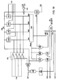
- FIG. 3 A preferred embodiment of a transmitter T x suitable for use in a system according to the present invention is shown in Fig. 3 in the form of a detailed block diagram.
- a transmitting antennae coil 36 is connected in parallel to a tuning capacitor 37 via the output terminals A and B of the transmitter, thus constituting an LC-tank 38 with resonance frequency
- This resonance circuit 38 is connected to DC-power supply lines 39,40 via a resistor 41 and a power switch 42 (HEX-FET, for example) controlled by a signal 43.
- R d is connected via another power switch 44 in parallel to the tuning capacitor 37.
- the power switch 44 is controlled by a command 45. Both commands 43 and 45 form a set of commands designated in Fig. 1 as 12 or 13.
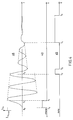
- the time diagram in Fig. 4 shows the current I Tx (46) in the transmitting antenna loop and signals 43 ("charge”) and 45 ("dump") controlling, correspondingly, the beginning and the energy level of the transmission.
- the resonance circuit 38 is energized when connected for a short time to the power supply via switch 42 and resistor 41, whilst the switch 44 is open.
- the critical value of the resistor 41 which is has been chosen as the most effective one.
- This decay does not affect the performance of the system, according to the present invention, because the transmission pulse is relatively short, containing only a few periods of the resonance frequency ⁇ ⁇ o whereas the Q-factor of the resonance tank 38 in the preferred embodiment is relatively high, being in the order of 50 and, besides, as will be shown later, a decay of the surveillance field is taken into consideration in the signal processing.
- any transmitter can be switched on at any predetermined moment t o and the strength of the transmitting field can be reduced in a controllable manner to various intermediate levels, including zero in a practical sense. A use of all these features, which are important to the present invention, will be disclosed later on.
- any two neighbouring antennae transmit fields alternating with the same frequency ⁇ ⁇ o simultaneously and in anti-phase during every second cycle.
- the second option uses two identically wound antennae which are connected to the output terminals of their respective transmitters in mutually reversed manner. In both these cases all transmitters are switched on at exactly the same moment.
- a preferred embodiment of the present invention utilizes a third option, which unlike the first two does not need either differently wound transmitting antennae or differently assembled gate panels containing both the antennae and the transmitters.
- This preferred option uses transmitting antennae (3 and 4 for example) identically wound and identically connected to the terminals A1, B1 and A2, B2 of their respective transmitters T x1 and T x2 .
- the start and direction of every transmitting antenna coil winding are indicated in Fig. 1 by dots and arrows. Every two neighbouring transmitters (T x1 and T x2 for instance), being under different commands 12 and 13 are switched on with a time interval, which is equal to the duration of half a period of the transmitting frequency f o , as illustrated in Fig. 5, where the currents and of both transmitters T x1 and T x2 are shown.
- any two neighbouring transmitting antennae e.g. 3 and 4 will emit their electromagnetic fields in anti-phase.
- both transmitting and receiving antennae are not only sharing the same plane of a gate panel, but the receiving antenna loop does rather closely follow the contour of a transmitting antenna loop.
- Such an arrangement allows an increase in the sensitivity of the system by making sure that a majority of the magnetic lines created by the transmitting antenna loop will intersect with an area encircled by the receiver antenna loop. But such proximity of the two antennae results in a very high level of noise induced into the receiving antenna by the primary field of the transmitting antenna, unless certain measures are awaken. This noise is proportional to the derivative of the primary field and has exactly the same harmonic content as the current in a transmitting antenna has.
- the block diagram of the preferred embodiment of the receiver R x is shown in Fig. 6. It comprises four notch filters 47, 49, 50, 51, a preamplifier 48 and a synthesizer 52.
- the notch filters 47, 49, 50, and 51 are tuned to suppress the first four consecutive odd harmonics fo, 3fo, 5fo and 7fo of an interrogation field.
- These notch filters have a double T-bridge topography each, and they are passive in order not to have a very high Q, considering possible deviation of the frequencies to be notched and the tolerances of this filter's R-C components.
- the preamplifier 48 being shown as one unit in Fig. 6, consists, in practice, of several stages placed as buffers between and after the passive filters 49, 50, 51. Each of these stages has a gain greater than one.
- the very first stage uses a very low noise operational amplifier and is purposely placed after the first notch-filter 47 in order not to be saturated by the strong noise originated by the interrogation field in the receiver antenna.
- the preamplifier 48 also contains elements of the synthesizer, which for explanatory purposes is shown as a separate block 52 in Fig. 6.
- a signal generated by a magnetic tag in the interrogation field hereafter will be called the "original tag signal”. It could be seen at the output of the receiving antenna were this signal to be separated from all noises and placed on the ideal zero-line.
- the original tag signal is a video pulse and is very narrow in comparison with the period of an interrogation field. Therefore, it can be considered as a single impulse, best described by its spectrum rather than by its harmonics content.
- a shape, and therefore a frequency spectrum of the original tag signal is a product of the following two factors: the shape of the hysteresis loop of the magnetic material of the tag, and the rate of change of the electro-magnetic field which executes the magnetic flip-over of the tag inductance. Neither of these two factors is constant due to the differences in parameters of soft magnetic materials and also due to the differences in the strengths of the interrogation field components actually coupled with the tag (which may have any orientation and position within the gate). That means that the original tag signal can have a wide variety of shapes with varying widths and slopes, and by no means can be considered as fully defined for purposes of signal processing.
- Fig. 7 shows different possible original tag signals and their respective spectra S(f).
- the shapes of the tag signals shown in Fig. 7 are a sine (53), a rectangle (54), an elevated sine (55) and a triangle (56). All of them have an amplitude A and a duration ⁇ o (which, for signals 55 and 56, is measured at the half-amplitude level).
- Spectra S(f) in Fig. 7 have been normalized with respect to the values of the product A ⁇ o .
- Fig. 8 is drawn as an expansion of the first and most powerful band of the spectra in Fig. 7.
- Fig. 8 within the frequency range from zero to approximately the spectra S(f) (53-56) of the differently shaped original tag signals are practically flat and this is what all these different spectra have in common. Therefore, according to the present invention, this flat portion of the original tag signal spectrum is used to transform and thus modify different kinds of original tag signals into a standard tag signal with an apriory specified shape.
- Such a modified tag signal is an amplitude-modulated AC-pulse with carrier frequency f T , duration ⁇ T and an apriory defined geometry of an envelope.
- This modified tag signal is cut off from the above described flat top portion of the spectra of the differently shaped original tag signals.
- the extraction of the modified tag signal spectrum is done by a synthesizer (52 in Fig. 6) which has gain-versus-frequency characteristic G(f) similar to the spectral function S T (f) of the modified tag signal (at least within the band where the vast part of this modified tag signal energy is located).
- the upper limit for the frequency band of this synthesizer is set by a frequency at which the "flat" portion of the original tag signal spectrum starts rolling off (note that the limited bandwidth of the active components in the receiver circuitry - such as operational amplifiers - contribute to this roll-off process, too).
- a band of the synthesizer has a lower limit f min which should be higher than the highest frequency notched by the filters in order to suppress the harmonics of the interrogation field.
- the band limitation imposed on the synthesizer demands that the modified tag signal has to have negligible side bands of its spectrum and most of its energy to be concentrated in the central band of the spectrum and this central band in its turn must be within the limits [f min -f max ]. This condition is met excellently by an AC-pulse with an envelope described as sin existing only when 0 ⁇ t ⁇ T , where ⁇ T is the duration of this pulse and also half of a period of its sinusoidal envelope.
- the modified tag signal has been given such a "half a period of a sine" envelope as illustrated in Fig. 9.
- the theoretical spectrum S T (f) is shown in Fig. 8 by the dotted line 57 and the practical characteristic G(f) of the synthesizer is given here as the curve 58.
- This curve 58 is marked at the four points corresponding to the first four consecutive odd harmonics of the interrogation field suppressed by the notch filters 47, 49, 50 and 51 in Fig. 6.
- the synthesizer 52 is a kind of a band-pass filter. There are different ways to design the synthesizer. In the preferred embodiment it is done by the use of elementary (single pole) R-C filters in both high-pass and low-pass configurations.
- the G(f)-characteristics of the synthesizer is symmetrical around the central frequency f T in a manner described as
- the number of low-pass R-C filters used in the synthesizer is greater than the number of high-pass R-C filters and, moreover, these elementary R-C filters, in general, have their poles set at different frequencies in order to create a G(f)-function close enough to the theoretical spectral function S T (f) of the modified tag signal.
- the G(f) function of the synthesizer has a good similarity to the spectral function S T (f) of an AC-pulse with a sinusoidal envelope (as is shown in Fig.
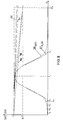
- Fig. 10 shows at 59 the sinusoidally varying interrogation field H o sin( ⁇ ot ) interacting with the magnetic material of the tag, biased by the earth magnetic field H e and having a linearly sloped hysteresis characteristic saturated at inductance levels of +B max and -B max and having coercive force of H c .
- the said interaction results in the generation of original tag signals, (rectangular for this example).
- the level of the interrogation field should always satisfy the condition of The earth magnetic field varies from the minimum of 10 A/m at the equator to the maximum of 80 A/m at the earth's poles and in most populated areas where the use of the system of the present invention is relevant H e ⁇ 50 A/m, whereas the typical value of a coercive force H c of soft magnetic materials used for security tags is less than 1 A/m.
- the modification of the tag signals by itself does not endow them with any unique distinctive features because any relatively narrow spike of an external noise will be transformed by the synthesizer into a signal shaped like a modified tag signal.
- the importance of the modification lies in the transformation of a tag signal originally shaped as a video pulse into an AC-pulse with an apriory known carrier frequency f T .
- such a modified signal will be treated by methods of synchronous detection and a certain use of these methods, as will be shown later, not only will provide a simple and easy way for build up of signal to noise ratio, but also will be instrumental for a deliverance from external periodic noise originated, for example, by horizontal deflections of various video monitors (T.V., computerized cash registers, etc.).
- the modified tag signals (62, Fig. 10) are discrete signals and therefore the system of the present invention uses the windows technique. Although the exact locations of the tag signals (i.e. initial phases of the modified tag signals) are unknown, as explained previously, their approximate positions are known to be near the zero-crossings of the interrogation field.
- each window 63 starts some time before its respective zero-crossing and ends some time past the same zero-crossing, being long enough to contain the modified tag signal 62 considering all possible deviations in the initial phase of this signal. All windows 63 have the same duration T w and each window is separated by gaps from the neighbouring windows.
- Gaps are important for the following reasons.
- a metal object like for example a shopping cart, made of a hard magnetic material (such as iron or nickel) may become magnetically saturated by the interrogation field, and will then generate a signal 64 which upon modification 65 might be mistaken by the system for a modified tag signal.
- These hard magnetic materials have a much wider hysteresis loop 66 than the soft magnetic materials have. Therefore in order to saturate objects made of hard magnetic material a much stronger field is required and in many cases signals resulting from the distortion of a field with a moderate strength (which is in the middle area of the gate) by such metal objects probably will fall between the windows because the sinusoidal interrogation field 59 is strongest halfway between its zero-crossings.
- the signals generated by this object can be close enough to the field zero-crossings to be inside the windows.
- the security tag usually comprises not only a soft magnetic material strip but also a number of chips made of hard magnetic material.
- the tag is deactivated by magnetizing these chips.
- Their residual field H b biases the narrow hysteresis of the tag (67, Fig. 10) which no longer will be affected by the interrogation field as long as the field is weaker than H b .
- H b biases the narrow hysteresis of the tag (67, Fig. 10) which no longer will be affected by the interrogation field as long as the field is weaker than H b .
- H b e.g. in close proximity to a transmitting antenna
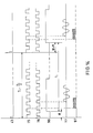
- Fig. 11 is a time diagram containing a minimal set of controller commands entering the signal processor during every one of the several transmission periods constituting the full surveillance cycle.
- the first three lines (43, 45 and 46) in Fig. 11 are repeated from Fig. 4 for explanatory purposes, showing command 43 initiating every transmission pulse 46 (and, thus, the transmission period itself) and command 45 changing the level of the field 46.
- the train of windows 71 has very stable time parameters assured by the use of a crystal clock in the controller 14.
- the windows train 71 can be seen as a periodic process with a few windows (between W (-) and W h ) missing.
- the period of the windows train is equal to the value of half a period of the interrogation field frequency.
- a possible deviation of an actual field frequency from its nominal value f o has been taken into consideration by giving the windows an extra length in order not to miss any of the expected modified tag signals.
- the time shift ⁇ between the moments where the transmission of the field 46 and the train of windows 71 start, although controlled by the crystal clock can be different for different transmission periods discretely deviating from its nominal value ⁇ o by ⁇ where T T is the period of the modified tag signal. This deviation is also being considered in the windows duration T W .
- the very first window W g in the train 71 is meant for an automatic setting of the system gain each time the surveillance cycle starts, so that the window W g , although being formed for every transmission period, is active in the very first one only, setting the proper gain which will be maintained for the duration of the entire surveillance cycle.
- a preferred practical way of an automatic gain setting will be described later on.
- the windows between W g and W (-) are "main" windows searching for the modified tag signals.
- the number of these main windows can vary from one to many. Practically, the number of main windows is determined by a compromise between the conflicting factors of the reliability of signal processing results and the time consumption of producing them.
- Four main windows W1-W4 are used in the preferred embodiment of the system.
- Windows W (-) and W h are auxiliary windows. They are used to check whether the signals discovered by the main windows have been true (being originated by an active tag) or whether they have been generated in a strong field by either a metal object or by a deactivated tag. This discrimination is based upon the assumption that when placed in the middle part of the security zone (where the field is weakest) neither a metal object nor a deactivated tag will produce a signal which could be seen in the main windows W1-W4.
- the signal processor gets signals 20 and 21 from both receivers 15 and 16. These signals obviously must enter the signal processor in such a manner as to be summed and not subtracted from each other.
- the summing mode is maintained throughout the transmission period except for the interval (line 72, Fig. 11) where the first auxiliary window W (-) is located. Following the command 72 the summing mode of the signal processor is changed for a subtracting mode. If the main windows W1-W4 indicate the presence of a signal and there is no signal in window W (-) , then the logical conclusion will be drawn that the signal is a true tag signal.
- the second auxiliary window W h is employed. This window is used when, following the first of the commands 45 the strength of the interrogation field 46 has been reduced (three or four times, for example) in comparison with the field strength at the time of all the previous windows in the train 71. If the signal still appears in the window W h , although attenuated to approximately the same degree as the field 46 has been, than the signal must be true. A false signal generated by a metal object or by a deactivated tag will not appear in the window W h because in a weak field nothing but a true tag signal can be observed in the windows.
- Both windows W N1 and W N2 have the same duration T w as the windows of the train 71 have.
- the window W N2 (74) always lags behind the window W N1 (73) by and in its turn the window W N1 is rigidly synchronized with the train of windows 71.
- Fig. 12 is a block-diagram of the synchronous detector as used in the preferred embodiment of the system.
- Fig. 12 block 78 is a double-output phase detector, comprising an inverting unity gain amplifier 79 and two double-throw analog switches one of which is controlled by the "in-phase” reference 75 and the second is controlled by the "quadrature” reference 76.
- the modified tag signal 77 which can be described as A*sin( ⁇ ⁇ Tt + ⁇ ), providing that its envelope, as a function of time, is significantly slower than its carrier
- the low-frequency components of its respective output signals will be A*cos ⁇ and A*sin ⁇ .
- both output levels from the integrators 82,83 can be applied to the inputs of a "magnitude extractor" 87 via respective switches 85,86 controlled by command 110.
- the magnitude extractor is set to execute the non-linear mathematical operation ⁇ V12 ⁇ + ⁇ V22 ⁇ .
- a simple and therefore preferred embodiment of the magnitude extractor 87 is shown as a block diagram in Fig. 13. It comprises: two full wave rectifiers 89,90 providing at their outputs absolute values
- This level 88 is proportional to the magnitude resulting from the synchronous stacking of n modified tag signals, and is independent of their unknown initial phase ⁇ , no matter what positions these signals occupy within their respective windows. The last statement is true because the initial phase ⁇ of a modified tag signal is measured with respect to the beginning of the transmission period to which this signal belongs and not to the beginning of a window surrounding this signal.
- Fig. 14 Parts of two transmission periods, which together make up an accumulation cycle are shown here in the form of a time diagram. Each transmission period starts by command 43 at which moment the in-phase and quadrature reference waveforms 75,76 start also. Two corresponding modified tag signals 77 in both transmission periods have identical initial phases ⁇ , being originated by identical parts of the interrogation fields (not shown), which are identical in both transmission periods. These signal 77 are well within their respective windows 96 which are shifted with respect to each other by half a period of the reference waves (75,76). According to the recent explanation, at the end of the second window 96, the output levels of integrators 82 and 83 (Fig. 12) will be doubled and, thus, the output level 88 of the magnitude extractor 87 will be doubled, too.
- the system of the present invention having the accumulation cycle of two transmission periods with an interval between their starting points which differs by half a period of the reference waveforms 75,76 from the interval T1 between the moments where two respective trains of windows start, will reject all periodic noises with repetition rates being multiples of f N1min , for which T1f N1min is still an integer.
- Such a plurality of periodic noises will hereafter be referred to as a "group of periodic noises”. If the modified tag signal is also present in those windows 96, the output level 88 of the magnitude extractor 87 will reflect a doubled magnitude of the modified tag signal, whereas a random noise contribution to the output level (88) will be diminished.
- Fig. 15 is a visual example of an accumulation cycle structured in such a way that two different groups of periodic noises with repetition rates which are multiples of f N1min and f N2min will be rejected when T1f N1min and T2f N2min are integers.
- any periodic noise with repetition rate f No such that the product T w f No is an even number will not cause any change in the output levels of the synchronous detector integrators by the end of any one window.
- the shortest windows have to be 128 ⁇ sec long. Obviously the multiples of this frequency will be rejected, too.
- auxiliary windows W N1 (73) and W N2 (74) are used in each transmission period being placed where the interrogation field 46 (Fig. 11) practically does not exist in order to assess noise hitting the system. These windows are shifted relative to each other by half of their duration T w . The purpose and use of this will be explained now with the help of Fig. 16.
- the contents of these windows 73,74 are also subject to the synchronous detection using reference waveforms 75,76. It may well be that in one of the windows, W N1 (73) for example, not a whole pulse of the periodic noise 98 but only rear and front fractions of two such noise pulses will be seen. In this case the magnitude of the noise can be greatly underestimated by the synchronous detector. But, as is clearly shown in Fig. 16, the second window W N2 (74) has a whole pulse of noise 98 and the synchronous detector processing this window (W N2 ) can be more accurate in the assessment of the magnitude of noise.
- the output levels 88 of the magnitude extractor 87 which are related to the windows W N1 (73) and W N2 (74), are applied sequentially to a peak detector 124 (Fig. 18), the output signal of which corresponds to the highest level of noise.
- the output level 30 of the peak-detector 124 is used as a threshold value.
- the output level 30 of this peak detector 124 is also instrumental for a dynamic indication of the magnitude N of periodic noises during the search for optimal values (T1, T2, etc.) of the accumulation cycle.
- search procedures will be explained now, first using the search for the proper value of T1 only as a basic example.
- the search can be described as a sweep along the values of T1 in a certain range, performed by the controller 14, using as feedback 26 (Fig. 1) the values N of the noise magnitudes which are matured at the end of each surveillance cycle.
- the search comprises a number of stages, each of which can include more than one surveillance cycle in order to produce inside the controller 14 an average N ⁇ of several values N and improve by that the accuracy of the evaluation of a periodic noise in the presence of other sporadic and random noises.
- the interval T1 as divided inside the controller 14 consists of two parts: a fixed one T 1min , which has not to be shorter than a duration of the transmission period, and a variable part ⁇ T1, which is being increased by an increment of ⁇ t at the end of every stage of the search.
- the search can start when either the noise N ⁇ increases above some critical level or just becomes steadily greater than what it has been.
- the search also can be conducted periodically as a routine procedure, once every few minutes for example.
- N ⁇ 1 At the end of the first stage a new noise value N ⁇ 1 emerges and loads an "N-memory" which can be a "sample and hold" for example.
- ⁇ T1 gets its first increment ⁇ t so T1 is set as (T 1min + ⁇ t) for the entire duration of the second stage.
- N ⁇ 2 At the end of the second stage a new noise level N ⁇ 2 will be checked against the stored value N ⁇ 1.
- a new noise level N ⁇ 3 will be compared with the magnitude of noise stored in the "N-memory" and a decision regarding both (N- and ⁇ T1-) memories will be made based upon the results of this comparison in exactly the same way as described above.
- T 1max T1+(S-1) ⁇ t .
- the lowest level of noise N ⁇ b stored in N-memory can be used as a reference for the decision to start a new search when the current level of noise becomes much greater than N ⁇ b .
- N ⁇ b For this purpose, considering that the time interval between two searches can be rather long, a preference should be given to the organization of the N-memory in a digital way using an analog to digital conversion for example, rather than the "sample and hold" technique.
- the interval T2 should be broken into two parts as well (consisting of a fixed part T 2min and a variable part ⁇ T2) and the controller 14 should have an additional ⁇ T2-memory.
- every surveillance cycle consists of two similar accumulation cycles, each of which comprises two transmission periods with the same time shift T1 between them in both accumulation cycles.
- T1 time shift
- the system is able to reject two groups of periodic noises (which is more than sufficient for most practical applications), while spending time to search for the optimal value of only one interval T1.
- the duration of the surveillance cycle containing 4 transmission periods is equal to 22.5 msec.
- Fig. 17 and 18 are block diagrams of the first and second parts of a preferred embodiment of the signal processor (18, in Fig. 1 for example) suitable for use in a system according to the present invention.
- the output signals 20,21 of their respective receivers 15 and 16 (Fig. 1) are applied to the inputs of and adder 99 (Fig. 17).
- the adder contains a switch (not shown) which upon receiving command 72 from the controller 14 changes the phase of one of the input signals (either 20 or 21) by 180°, thus causing the adder 99 to act as a subtractor for signals 20 and 21 once they are in the window W (-) . At all other times the adder 99 is in a summing mode.
- the output 100 of the adder 99 is connected to the input of an automatic gain selector 101.
- the working value of the gain is set during the very first window W g in the very first transmission period for the entire time of the surveillance cycle.
- the criterion of choosing the gain is that the signal 77 at the output of the gain selector 101 must not exceed a predetermined level which is below saturation.
- the signal 77 is applied to the analog input of the phase detector 78, both reference inputs of which are supplied by in phase (75) and quadrature (76) reference waveforms respectively.
- Both outputs ("sin” and “cos") of the phase detector 78 are connected to the respective inputs of eight identical units 102-109. Each of these units contains two integrators, the inputs and outputs of which are connected to their respective analog switches in a manner shown in that part of Fig. 12 which is located between the phase detector 78 and the magnitude extractor 87. All integrators in the units 102-109 are reset prior to the beginning of each accumulation cycle following command 84 from the controller 14.
- the units 102-109 together with the phase detector 78 and with the magnitude extractor 87 constitute eight synchronous detectors dedicated to processing information contained in the eight respective windows W1-W4, W (-) , W h , W N1 and W N2 as has been described in greater detail for window W1.
- Each unit 102-109 will supply the integrals (i.e. the output levels of its integrators) to the respective inputs V1 and V2 of the magnitude extractor 87 following commands 110-117.
- the commands 110-117 are originated by the controller 14 during the last transmission period of every accumulation cycle (i.e. during the second and fourth transmission periods), after their respective integrals in the units 102-109 have been matured.
- Commands 110-117 must not overlap in order not to violate the time-sharing use of the magnitude extractor (87). For that reason commands 110-115 lag behind the rear edges of their corresponding windows (W1-W4, W (-) , and W h ) of the train 72 (Fig. 11), whereas the commands 116 and 117, considering that their respective windows W N1 and W N2 overlap, must act in series starting after the termination of the last window W N2 .
- the magnitude extractor (87) presents at its output 88 magnitudes M1-M4, M (-) , M h , M N1 and M N2 either of signal or of noise in the same order in which the windows (W1-W N2 ) follow each other.
- the second part of the signal processing deals with the identification of the magnitudes 88 in order to make a decision regarding the necessity for an alarm.
- the respective magnitudes (M1-M4) become matured and are loaded into corresponding sample and hold units 118-121 following commands 122 which are derived from commands 110-113. From now and until the end of the surveillance cycle these main magnitudes M1-M4 are stored, which enables the necessary checks to be performed throughout the whole surveillance cycle.
- the checks are divided into two groups: a static examination and a dynamic examination.
- a static examination is done by the unit 123 to the inputs of which the values of the "main" magnitudes M1-M4, stored in the memories 118-121, are applied.
- the static examiner (123) contains a number of adders and comparators. One of the adders produces an average value M ave of all stored magnitudes M1-M4.
- the biasing effect of the earth magnetic field is such that not only the initial phases but also the magnitudes of the modified tag signals originated by the positive transitions of an interrogation field (i.e. when the sinusoidal field is going up from its minimal value to the maximal one) will have, in general, different values from the ones obtained at the negative transitions of the field. That means that in the presence of a tag, the odd numbered values M1 and M3 are different from the even numbered ones M2 and M4, and the difference is much more noticeable in a weak field. But, strictly speaking, the magnitude values of the tag signals are not equal even within the same group: M1>M3 and M2>M4, due to an exponential decay of the field.
- the static examiner (123) compares them in pairs using its adders: each pair is a sum of two magnitudes taken from both ("odd” and "even") groups. In that way, when the tag is present, all these sums (M1+M2, M1+M4, M2+M3 and M3+M4) are expected to be within a rather narrow range. In the preferred embodiment of the system with consideration of the field decay, the system's internal noise and the tolerances of component parameters, this range is established as ⁇ 15% when comparing (M1+M4) with (M2+M3), and as ⁇ 25% for the comparison between (M1+M2) and (M3+M4).
- the next two tests are designed to verify whether the signal (126) is true or is a result of either a metal object or a deactivated tag in a strong field. These two tests are based upon the method, which has been disclosed previously in greater detail.
- two comparators 127,128 and two latches 129,131 are used.
- the comparators 127,128 have at one of their inputs a common signal 88 from the magnitude extractor 87. Their second inputs use references derived from the average level M ave of the "main" magnitudes M1-M4 as supplied by the static examiner 123.
- the latches 129,131 are enabled by their respective strobes 130,132 to store the logic levels existing at the time of the strobes at the outputs of their respective comparators 127,128.
- the strobe 130 is derived from command 114 during the second transmission period only. It starts after the build-up of the level M (-) at the output of the magnitude extractor 87 (during two successive windows W (-) ) has been completed. If at the time of the strobe 130 the level M (-) is lower at least by a predetermined percentage, for instance 20%, than M ave then the output of the comparator 127 will be high and will be stored in the latch 129, appearing at one of the inputs of the AND-gate (143).
- the strobe 132 is derived from command 115 also during the second transmission period only. This strobe follows the second of the windows W h , both of which are located in these parts of the transmission periods when the interrogation field is three to four times weaker. If by the end of the second window W h the accumulated magnitude M h is also smaller than M ave in a slightly higher ratio than the field has been weakened, then the logic "1" at the output of the comparator 128 will be latched in 131 by strobe 132 and will be applied to yet another input of the AND-gate 143.
- the probability of false alarms due to external random noise, caused for example by brushes of electrical motors, is greatly reduced by checking the repeatability of the corresponding main magnitudes M1-M4 in both accumulation cycles.
- the repeatability test utilizes a four-channel analog multiplexer 133, a range comparator 135, an AND-gate 136 and a counter 138.
- the multiplexer (133) is controlled by commands 134 which are derived from commands 110-113 during the fourth transmission period.
- the commands 134 select the stored values M1-M4 to appear in sequence at the output of the multiplexer 133.
- the appearance of the stored levels M1-M4 coincides in time with the "live" levels M1 ⁇ 2-M4 ⁇ 2 as they emerge from the output 88 of the magnitude extractor 87 during the second accumulation cycle.
- One of the inputs of the comparator 135 is connected to the output of the multiplexer 133, the second input of the comparator 135 is connected to the output 88 of the magnitude extractor 87.
- the range comparator 135 checks whether the "live" values M1 ⁇ 2-M4 ⁇ 2 are repeating their corresponding "frozen” values M1-M4 with a predetermined accuracy of, say, ⁇ 20%.
- the output of the comparator 135 is connected to one of two inputs of the AND-gate 136, to the second input of which four strobes 137 are applied. These strobes are derived from commands 110-113 during the fourth transmission period.
- the last test concerns itself with an examination by a comparator 140 whether the average value M ave of the main magnitudes M1-M4 is actually higher (at least by 20% for example) than the level of the dynamic threshold 30.
- the threshold value is provided by peak-detector 124 which selects and stores the highest value among the noise magnitudes M N1 , M N2 appearing in every accumulation cycle throughout the whole surveillance cycle. Therefore the peak detector 124 is connected to the output 88 of the magnitude extractor 87 via an analog switch 144, which is closed every time when the commands 116 and 117 are applied to the inputs of the OR-gate 145, controlling the switch 144.
- the peak detector 124 is cleared by command 125 from the controller 14 at the beginning of every surveillance cycle.
- the threshold value 30 is considered to be mature at the end of the last command 117 (in the fourth transmission period), and only then the logic level at the output 141 of the comparator 140 can be trusted, considering the dynamic nature of the signal 30 at the output of the peak detector 124.
- the comparator 140 supplies its output signal 141 to one of two yet remaining unused inputs of the AND-gate 143, and to the last of its inputs a strobe 142 is applied.
- the strobe 142 is originated in the controller 14 just following the rear edge of the last command 117 in the surveillance cycle.
- the meaning of the strobe 142 is "make a decision”.
- the decision to set an alarm will be represented by a high level of the output 32 of the AND-gate 143, when all its inputs are high.
Priority Applications (3)
| Application Number | Priority Date | Filing Date | Title |
|---|---|---|---|
| EP92200765A EP0561062A1 (fr) | 1992-03-17 | 1992-03-17 | Méthode et système électromagnétique de sécurité pour protéger des objets surveillés dans une zone de surveillance |
| US07/871,680 US5276430A (en) | 1992-03-17 | 1992-04-21 | Method and electromagnetic security system for detection of protected objects in a surveillance zone |
| CA002091790A CA2091790A1 (fr) | 1992-03-17 | 1993-03-17 | Methode et systeme de surveillance electromagnetique pour zone de securite |
Applications Claiming Priority (1)
| Application Number | Priority Date | Filing Date | Title |
|---|---|---|---|
| EP92200765A EP0561062A1 (fr) | 1992-03-17 | 1992-03-17 | Méthode et système électromagnétique de sécurité pour protéger des objets surveillés dans une zone de surveillance |
Publications (1)
| Publication Number | Publication Date |
|---|---|
| EP0561062A1 true EP0561062A1 (fr) | 1993-09-22 |
Family
ID=8210484
Family Applications (1)
| Application Number | Title | Priority Date | Filing Date |
|---|---|---|---|
| EP92200765A Withdrawn EP0561062A1 (fr) | 1992-03-17 | 1992-03-17 | Méthode et système électromagnétique de sécurité pour protéger des objets surveillés dans une zone de surveillance |
Country Status (3)
| Country | Link |
|---|---|
| US (1) | US5276430A (fr) |
| EP (1) | EP0561062A1 (fr) |
| CA (1) | CA2091790A1 (fr) |
Cited By (9)
| Publication number | Priority date | Publication date | Assignee | Title |
|---|---|---|---|---|
| EP0704830A1 (fr) * | 1994-09-28 | 1996-04-03 | Sensormatic Electronics Corporation | Dispositif électronique impulsionnel de surveillance d'article utilisant les techniques de système expert pour l'optimisation dynamique |
| WO1996031855A1 (fr) * | 1995-04-07 | 1996-10-10 | Minnesota Mining And Manufacturing Company | Systeme de surveillance electronique d'articles a filtrage adaptatif et detection numerique |
| EP0704829A3 (fr) * | 1994-09-28 | 1997-09-10 | Sensormatic Electronics Corp | Système de commande d'entrées de récepteur d'un système électronique de surveillance d'articles à optimisation dynamique utilisant un système expert |
| EP1008972A2 (fr) * | 1998-12-09 | 2000-06-14 | 1336700 Ontario Inc. | Système de sécurité pour surveiller le passage d'articles |
| WO2001015102A1 (fr) * | 1999-08-23 | 2001-03-01 | Sensormatic Electronics Corporation | Emetteur pour systeme electronique de surveillance d'articles |
| WO2002063585A1 (fr) * | 2001-02-05 | 2002-08-15 | Sensormatic Electronics Corporation | Suppression d'un bruit de signal de niveau eleve en surveillance d'articles electroniques |
| FR2832254A1 (fr) * | 2001-11-15 | 2003-05-16 | Sidep | Procede, dispositif et antenne de detection d'etiquette radiofrequence a l'aide d'une pluralite de boucles de detection |
| WO2008002304A1 (fr) | 2006-06-27 | 2008-01-03 | Sensormatic Electronics Corporation | Fonctionnement synchronisé sans fil de systèmes de surveillance d'articles électroniques (eas) impulsionnels |
| US7535338B2 (en) | 2006-06-27 | 2009-05-19 | Sensormatic Electronics Corporation | Wireless synchronized operation of pulsed EAS systems |
Families Citing this family (21)
| Publication number | Priority date | Publication date | Assignee | Title |
|---|---|---|---|---|
| US5432518A (en) * | 1993-06-15 | 1995-07-11 | Texas Instruments Incorporated | Closed slot antenna having outer and inner magnetic loops |
| FR2711440B1 (fr) * | 1993-10-18 | 1996-02-02 | France Telecom | Dispositif à pureté spectrale pour l'échange d'informations à distance entre un objet portatif et une station. |
| AU716217B2 (en) * | 1994-09-28 | 2000-02-24 | Sensormatic Electronics, LLC | Pulsed electronic article surveillance device employing expert system techniques for dynamic optimization |
| US6690963B2 (en) | 1995-01-24 | 2004-02-10 | Biosense, Inc. | System for determining the location and orientation of an invasive medical instrument |
| US5625341A (en) * | 1995-08-31 | 1997-04-29 | Sensormatic Electronics Corporation | Multi-bit EAS marker powered by interrogation signal in the eight MHz band |
| US6320507B1 (en) * | 2000-04-07 | 2001-11-20 | Sensormatic Electronics Corporation | Method for synchronization between systems |
| US7049933B1 (en) * | 2000-08-25 | 2006-05-23 | Rf Code, Inc. | Identification device detection using multiple signal combination |
| US7253717B2 (en) * | 2000-11-29 | 2007-08-07 | Mobile Technics Llc | Method and system for communicating with and tracking RFID transponders |
| US7212117B2 (en) * | 2001-02-08 | 2007-05-01 | Sensormatic Electronics Corporation | Automatic wireless synchronization of electronic article surveillance systems |
| US6906628B2 (en) * | 2001-03-13 | 2005-06-14 | Sensormatic Electronics Corporation | Varying field electronic tag detection system |
| ES2614734T3 (es) * | 2001-03-26 | 2017-06-01 | Sensormatic Electronics, LLC | Filtros de detección digital para la vigilancia electrónica de artículos |
| US6836216B2 (en) * | 2002-05-09 | 2004-12-28 | Electronic Article Surveillance Technologies, Ltd. | Electronic article surveillance system |
| SI21392A (sl) * | 2002-12-24 | 2004-06-30 | Vinko Kunc | Postopek za avtomatsko nastavitev ojačenja izpraševalnikovega sprejemnika v brezkontaktnem identifikacijskem sistemu |
| US6987391B2 (en) * | 2003-06-16 | 2006-01-17 | Andeen-Hagerling, Inc. | Apparatus for and method of synchronous rejection |
| US7551080B2 (en) * | 2006-07-17 | 2009-06-23 | Sensormatic Electronics Corporation | Control for embedded and door-mounted antennas |
| US20080107219A1 (en) * | 2006-11-07 | 2008-05-08 | Sensormatic Electronics Corporation | Electronic articles surveillance system synchronization using global positioning satellite signal |
| ES2384856T3 (es) * | 2007-04-13 | 2012-07-13 | Alert Metalguard Aps | Procedimiento, dispositivo y sistema para prevenir falsas alarmas en un sistema antirrobo |
| JP5328976B2 (ja) * | 2010-02-18 | 2013-10-30 | 三菱電機株式会社 | 侵入物識別装置 |
| US8717181B2 (en) | 2010-07-29 | 2014-05-06 | Hill-Rom Services, Inc. | Bed exit alert silence with automatic re-enable |
| US8854045B2 (en) * | 2012-07-11 | 2014-10-07 | Pico Technologies Llc | Electronics for a thin bed array induction logging system |
| US20150097559A1 (en) * | 2013-10-04 | 2015-04-09 | Checkpoint Systems, Inc. | System and method for loss prevention using a magnetometer |
Citations (2)
| Publication number | Priority date | Publication date | Assignee | Title |
|---|---|---|---|---|
| WO1983002027A1 (fr) * | 1981-11-24 | 1983-06-09 | Myong Shin | Systeme antivol |
| US4527152A (en) * | 1979-09-14 | 1985-07-02 | Shin International, Inc. | Anti-shoplifting system |
Family Cites Families (6)
| Publication number | Priority date | Publication date | Assignee | Title |
|---|---|---|---|---|
| US3990065A (en) * | 1975-02-20 | 1976-11-02 | The Magnavox Company | Theft detection system |
| US4300183A (en) * | 1980-03-27 | 1981-11-10 | Richardson Robert H | Method and apparatus for generating alternating magnetic fields to produce harmonic signals from a metallic strip |
| US4429302A (en) * | 1981-10-08 | 1984-01-31 | I. D. Engineering, Inc. | Electronic security system with noise rejection |
| US4623877A (en) * | 1983-06-30 | 1986-11-18 | Knogo Corporation | Method and apparatus for detection of targets in an interrogation zone |
| CA1234891A (fr) * | 1983-10-20 | 1988-04-05 | 746278 Ontario Limited D/B/A I.D. Systems Canada | Vignette pour systeme de securite |
| CA1234892A (fr) * | 1984-02-16 | 1988-04-05 | Pierre Taillefer | Systeme de detection pour etiquettes anti-vol |
-
1992
- 1992-03-17 EP EP92200765A patent/EP0561062A1/fr not_active Withdrawn
- 1992-04-21 US US07/871,680 patent/US5276430A/en not_active Expired - Fee Related
-
1993
- 1993-03-17 CA CA002091790A patent/CA2091790A1/fr not_active Abandoned
Patent Citations (2)
| Publication number | Priority date | Publication date | Assignee | Title |
|---|---|---|---|---|
| US4527152A (en) * | 1979-09-14 | 1985-07-02 | Shin International, Inc. | Anti-shoplifting system |
| WO1983002027A1 (fr) * | 1981-11-24 | 1983-06-09 | Myong Shin | Systeme antivol |
Cited By (17)
| Publication number | Priority date | Publication date | Assignee | Title |
|---|---|---|---|---|
| EP0704830A1 (fr) * | 1994-09-28 | 1996-04-03 | Sensormatic Electronics Corporation | Dispositif électronique impulsionnel de surveillance d'article utilisant les techniques de système expert pour l'optimisation dynamique |
| EP0704829A3 (fr) * | 1994-09-28 | 1997-09-10 | Sensormatic Electronics Corp | Système de commande d'entrées de récepteur d'un système électronique de surveillance d'articles à optimisation dynamique utilisant un système expert |
| WO1996031855A1 (fr) * | 1995-04-07 | 1996-10-10 | Minnesota Mining And Manufacturing Company | Systeme de surveillance electronique d'articles a filtrage adaptatif et detection numerique |
| AU692696B2 (en) * | 1995-04-07 | 1998-06-11 | Minnesota Mining And Manufacturing Company | Electronic article surveillance system with adaptative filtering and digital detection |
| US6501381B1 (en) | 1998-12-09 | 2002-12-31 | 1336700 Ontario Inc. | Security system for monitoring the passage of items through defined zones |
| EP1008972A3 (fr) * | 1998-12-09 | 2001-04-11 | 1336700 Ontario Inc. | Système de sécurité pour surveiller le passage d'articles |
| EP1008972A2 (fr) * | 1998-12-09 | 2000-06-14 | 1336700 Ontario Inc. | Système de sécurité pour surveiller le passage d'articles |
| EP1369833A2 (fr) * | 1998-12-09 | 2003-12-10 | 1336700 Ontario Inc. | Système de sécurité pour surveiller le passage d'articles |
| EP1369833A3 (fr) * | 1998-12-09 | 2004-09-01 | 1336700 Ontario Inc. | Système de sécurité pour surveiller le passage d'articles |
| WO2001015102A1 (fr) * | 1999-08-23 | 2001-03-01 | Sensormatic Electronics Corporation | Emetteur pour systeme electronique de surveillance d'articles |
| WO2002063585A1 (fr) * | 2001-02-05 | 2002-08-15 | Sensormatic Electronics Corporation | Suppression d'un bruit de signal de niveau eleve en surveillance d'articles electroniques |
| AU2002243864B2 (en) * | 2001-02-05 | 2006-11-23 | Sensormatic Electronics Llc | Large signal noise cancellation in electronic article surveillance |
| FR2832254A1 (fr) * | 2001-11-15 | 2003-05-16 | Sidep | Procede, dispositif et antenne de detection d'etiquette radiofrequence a l'aide d'une pluralite de boucles de detection |
| EP1315135A1 (fr) * | 2001-11-15 | 2003-05-28 | Sidep | Antenne de détection d'étiquettes |
| WO2008002304A1 (fr) | 2006-06-27 | 2008-01-03 | Sensormatic Electronics Corporation | Fonctionnement synchronisé sans fil de systèmes de surveillance d'articles électroniques (eas) impulsionnels |
| US7535338B2 (en) | 2006-06-27 | 2009-05-19 | Sensormatic Electronics Corporation | Wireless synchronized operation of pulsed EAS systems |
| CN101506855B (zh) * | 2006-06-27 | 2011-10-12 | 传感电子公司 | 脉冲eas系统的无线同步操作 |
Also Published As
| Publication number | Publication date |
|---|---|
| US5276430A (en) | 1994-01-04 |
| CA2091790A1 (fr) | 1993-09-18 |
Similar Documents
| Publication | Publication Date | Title |
|---|---|---|
| EP0561062A1 (fr) | Méthode et système électromagnétique de sécurité pour protéger des objets surveillés dans une zone de surveillance | |
| US6131076A (en) | Self tuning system for industrial surveillance | |
| US4539558A (en) | Antitheft system | |
| US5461383A (en) | Wideband microwave detector | |
| AU606295B2 (en) | False alarm minimization and direction determination methods | |
| CA2101290C (fr) | Systeme de commutation electronique automatique permettant un traitement ameliore des signaux d'antenne | |
| AU721519B2 (en) | Pulsed interrogation signal in harmonic EAS system | |
| CA1056908A (fr) | Mode et appareil de localisation des derangements de ligne | |
| EP0646266B1 (fr) | Systeme de detection de vol faisant appel au traitement de signaux numeriques | |
| US5371490A (en) | System for electronic safeguarding against burglary using multiple transmitters and receivers | |
| EP0431341B1 (fr) | Circuit pour le rejet d'un signal interférant dans un système électronique pour la surveillance d'articles et procédé d'emploi | |
| US4104611A (en) | Suppressing constant frequency noise in seismic records | |
| CA2437801C (fr) | Combinaison differentiellement coherente pour systemes electroniques de surveillance d'articles | |
| US5877706A (en) | Ferromagnetic object detector | |
| US5900816A (en) | Anti-shoplifting security system utilizing a modulated transmitter signal | |
| US4524350A (en) | Detection logic and signal processing method and apparatus for theft detection systems | |
| US4535323A (en) | Preamplifying and signal processing method and apparatus for theft detection systems | |
| JP3803982B2 (ja) | 盗難防止システム | |
| US5703566A (en) | Anti-shoplifting security system | |
| US5995005A (en) | Theft checking system | |
| JPH03218490A (ja) | 金属体検知装置 | |
| JP3629342B2 (ja) | 物体識別装置 | |
| RU2450363C2 (ru) | Способ идентификации объектов и установка для его осуществления | |
| US5973597A (en) | Theft checking system | |
| SU1068800A1 (ru) | Двухчастотный дефектоскоп (его варианты) |
Legal Events
| Date | Code | Title | Description |
|---|---|---|---|
| PUAI | Public reference made under article 153(3) epc to a published international application that has entered the european phase |
Free format text: ORIGINAL CODE: 0009012 |
|
| AK | Designated contracting states |
Kind code of ref document: A1 Designated state(s): AT CH DE FR GB LI NL |
|
| 17P | Request for examination filed |
Effective date: 19940318 |
|
| 17Q | First examination report despatched |
Effective date: 19960208 |
|
| GRAG | Despatch of communication of intention to grant |
Free format text: ORIGINAL CODE: EPIDOS AGRA |
|
| GRAH | Despatch of communication of intention to grant a patent |
Free format text: ORIGINAL CODE: EPIDOS IGRA |
|
| STAA | Information on the status of an ep patent application or granted ep patent |
Free format text: STATUS: THE APPLICATION IS DEEMED TO BE WITHDRAWN |
|
| 18D | Application deemed to be withdrawn |
Effective date: 19970318 |