EP0798681A1 - Signal d'interrogation d'impulsion dans un système de surveillance d'articles fréquences harmoniques - Google Patents
Signal d'interrogation d'impulsion dans un système de surveillance d'articles fréquences harmoniques Download PDFInfo
- Publication number
- EP0798681A1 EP0798681A1 EP97104481A EP97104481A EP0798681A1 EP 0798681 A1 EP0798681 A1 EP 0798681A1 EP 97104481 A EP97104481 A EP 97104481A EP 97104481 A EP97104481 A EP 97104481A EP 0798681 A1 EP0798681 A1 EP 0798681A1
- Authority
- EP
- European Patent Office
- Prior art keywords
- signal
- pulses
- surveillance system
- electronic article
- article surveillance
- Prior art date
- Legal status (The legal status is an assumption and is not a legal conclusion. Google has not performed a legal analysis and makes no representation as to the accuracy of the status listed.)
- Withdrawn
Links
Images


Classifications
-
- G—PHYSICS
- G08—SIGNALLING
- G08B—SIGNALLING OR CALLING SYSTEMS; ORDER TELEGRAPHS; ALARM SYSTEMS
- G08B13/00—Burglar, theft or intruder alarms
- G08B13/22—Electrical actuation
- G08B13/24—Electrical actuation by interference with electromagnetic field distribution
- G08B13/2402—Electronic Article Surveillance [EAS], i.e. systems using tags for detecting removal of a tagged item from a secure area, e.g. tags for detecting shoplifting
- G08B13/2465—Aspects related to the EAS system, e.g. system components other than tags
- G08B13/2488—Timing issues, e.g. synchronising measures to avoid signal collision, with multiple emitters or a single emitter and receiver
-
- G—PHYSICS
- G08—SIGNALLING
- G08B—SIGNALLING OR CALLING SYSTEMS; ORDER TELEGRAPHS; ALARM SYSTEMS
- G08B13/00—Burglar, theft or intruder alarms
- G08B13/22—Electrical actuation
- G08B13/24—Electrical actuation by interference with electromagnetic field distribution
- G08B13/2402—Electronic Article Surveillance [EAS], i.e. systems using tags for detecting removal of a tagged item from a secure area, e.g. tags for detecting shoplifting
- G08B13/2465—Aspects related to the EAS system, e.g. system components other than tags
- G08B13/2468—Antenna in system and the related signal processing
- G08B13/2471—Antenna signal processing by receiver or emitter
Definitions
- This invention relates to electronic article surveillance (EAS) systems and, in particular, to such systems in which EAS markers are detected on the basis of harmonic perturbations of an interrogation signal.
- EAS electronic article surveillance
- markers designed to interact with an electromagnetic field placed at the store exit are secured to articles of merchandise. If a marker is brought into the field or "interrogation zone", the presence of the marker is detected and an alarm is generated. Some markers of this type are intended to be removed at the checkout counter upon payment for the merchandise. Other types of markers are deactivated upon checkout by a deactivation device which changes an electromagnetic characteristic of the marker so that the marker will no longer be detectable at the interrogation zone.
- harmonic EAS system One type of magnetic EAS system is referred to as a "harmonic" system because it is based on the principle that a magnetic material passing through an electromagnetic field having a selected frequency disturbs the field and produces harmonic perturbations of the selected frequency. The detection portion of the system is tuned to recognize certain harmonic frequencies, and, if such frequencies are present, an alarm is actuated.
- harmonic EAS systems are disclosed in, e.g., U.S. Patent Nos. 5,387,900 and 4,859,991. The assignee of the present application currently markets EAS systems of the harmonic type under the trademark "AISLEKEEPER".
- harmonic EAS systems have been successfully deployed and operated, improvement in the performance of such systems remains desirable.
- improvement in the performance of such systems remains desirable.
- Significant effort has been devoted to improving the ratio of reliability in detection to false-alarm susceptibility.
- a conventional interrogation signal used in harmonic EAS systems in the form of a continuous low-frequency sinusoidal signal, is shown as trace 10 in Fig. 1(a).
- a typical frequency for the interrogation signal is 73.125 Hz.
- interrogation signal transmitting antennas are provided on opposite sides of a store exit
- the interrogation signal field is strongest in locations that are close to one of the transmitting antennas, and is weakest at a central location that is substantially equidistant from the antennas.
- Trace 14 in Fig. 1(b) is indicative of the effective interrogation signal level at a point in the interrogation zone where the signal is lower in amplitude than the signal shown in Fig. 1.
- a marker exposed to the signal represented by trace 14 will switch at a point in the signal cycle that is closer to the peak of the cycle than was the case for a marker exposed to the higher-amplitude signal of Fig. 1(a).
- the gradient of the interrogation signal is lower at the switching points than in Fig. 1(a).
- the marker switches more slowly, and produces a marker signal (indicated by spikes 16) that is lower in amplitude than the spikes 12 of Fig. 1(a).
- the relatively low-amplitude spikes 16 of Fig. 1(b) are more difficult to detect than the higher-amplitude and sharper spikes 12 of Fig. 1(a).
- Another difficulty which results from the variation in field strength within the interrogation zone is variation in the timing of the marker signal from cycle to cycle of the interrogation signal, as the marker is carried between locations of varying field strength. Because of this variation or "jitter" in the timing of the marker signal relative to the interrogation signal, it can be difficult for the receiving equipment to distinguish between the marker signal and random noise impulses. Also, it becomes necessary to operate the detection equipment either continuously or throughout large portions of the interrogation signal cycle. This increases the likelihood that the detection equipment will generate false alarms in response to noise.
- Another possible solution would be simply to reduce the width of the interrogation zone (i.e., by moving the transmit antennas closer together), so that the signal at the point of minimum strength would be of higher amplitude, but this cannot be done without reducing the width of the store exit, which would cause inconvenience for store patrons and would not be acceptable to retailers, who are the customers for EAS systems.
- Still a further object is to maintain or improve system performance while reducing the strength of the interrogation field signal.
- an electronic article surveillance system including generating circuitry for generating an interrogation signal, the generating circuitry including an interrogation coil for radiating the interrogation signal in an interrogation zone, a marker secured to an article appointed for passage through the interrogation zone, the marker including an active element for generating a marker signal including harmonic signal components at harmonics of an operating frequency of the generating circuitry, and detecting circuitry for detecting the harmonic signal components of the marker signal generated by the active element, wherein the generating circuitry generates the interrogation signal in the form of discrete pulses.
- the detecting circuitry operates to detect the marker signal generated by the active element concurrently with times during which the discrete pulses are generated by the generating circuitry.
- the detecting circuitry may be arranged so that it does not operate to detect the marker signal at times that do not correspond to the discrete pulses.
- the discrete pulses may be such that each one has a pulse length that defines the operating frequency of the generating means, with all the pulses being equal in pulse length.
- the pulse length may have a duration that is within a preferred range from at least about 2 milliseconds to no more than about 20 milliseconds.
- the generating circuitry may operate to provide between each pair of successive pulses a time gap that has a duration at least as long as, and possibly five times as long as, the pulse length of the pulses.
- Each pulse may be formed so that it is one cycle of a sinusoidal signal or a triangular wave.
- the discrete pulses of the interrogation signal may be generated according to a binary code pattern so that a cycle of the interrogation signal is generated in each time period corresponding to a "1" value of the binary code pattern, and a pause in the interrogation signal is formed in each time period corresponding to a "0" value of the binary code pattern.
- the EAS system may include circuitry for determining a level of the detected marker signal, and the generating circuitry may selectively vary a level of the pulses of the interrogation signal according to the determined level of the detected marker signal.
- the generating circuitry may be operated to reduce the level of the pulses of the interrogation signal when the level of the detected marker signal exceeds a predetermined threshold value.
- the system may include interference detecting circuitry for detecting a periodically recurring noise signal present in the interrogation zone, and the generating circuitry may be operated to adjust a timing at which the pulses of the interrogation signal are generated so that the pulses do not coincide with the periodically recurring noise signal.
- the periodically recurring noise signal may have a timing that corresponds to the power line operating frequency.
- a method of operating a harmonic EAS system including the step of generating a harmonic EAS system interrogation signal in the form of discrete pulses. Further in accordance with this aspect of the invention, the method may include detecting EAS marker signals concurrently with the discrete pulses of the interrogation signal, and refraining from detecting marker signals at times that do not correspond to the discrete pulses.
- the effective frequency, and thus the gradient of the interrogation signal at the marker switching point can be increased, without exceeding regulatory limits on the average radiated power of the transmitting circuitry.
- a marker signal that is higher in amplitude, and therefore more easily detected, can thereby be produced.
- the pulsed generation of the interrogation signal makes it possible to limit the time windows during which tag signal detection operations must be performed, thereby reducing the possibility that the system will generate a false alarm in response to impulsive noise.
- "jitter" in the timing of the marker signal can be reduced, thereby making it easier to distinguish between the marker signal and ambient noise.
- the pulsed interrogation signal it becomes possible to shift the timing of the interrogation signal pulses relative to predictable noise (such as may be generated in relation to the power line signal) so that the timing of the marker signal is moved to a relatively low-noise time interval.
- the amplitude of the pulses can be reduced when a high-amplitude "marker-like" signal is generated, to aid in distinguishing between actual markers and other objects (such as shopping carts) that mimic EAS markers.
- pulsed interrogation signal makes it possible to operate the system at an over-all lower average power level, which permits the cost of the system to be reduced by decreasing the size of heat-sink structures on which transmitter power circuitry is mounted.
- Figs. 1(a) and 1(b) are illustrations of interrogation signal and marker signal waveforms generated in conventional harmonic EAS systems.
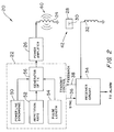
- Fig. 2 is a block diagram of an EAS system provided in accordance with an embodiment the present invention.
- Fig. 3 is a waveform illustration of a pulsed interrogation signal and a corresponding marker signal generated by the system of Fig. 2.
- Fig. 4 illustrates, by way of comparison, interrogation and marker signals respectively generated in accordance with the invention and in accordance with the prior art.
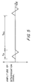
- Fig. 5 illustrates a triangular-wave pulsed interrogation signal generated according to an alternative embodiment of the invention.
- Fig. 6 illustrates adaptive timing of interrogation signal pulses, generated in accordance with a second alternative embodiment of the invention.
- Fig. 7 illustrates a coded-pulse interrogation signal generated in accordance with a third alternative embodiment of the invention.
- reference numeral 20 generally indicates a harmonic EAS system provided in accordance with the invention.
- the system 20 includes a transmit control circuit 22, a transmit antenna 24, a power amplifier 26 connected between the transmit control circuit 22 and the antenna 24, a marker 28 including an active element 30, a receive antenna 32, and a receiver circuit 34 connected to the receive antenna 32.
- Signal paths 36 and 38 are provided between the transmit control circuit 22 and the receiver circuit 34.
- the transmit control circuit 22 generates an interrogation signal waveform that is amplified by power amp 26 to form an antenna drive signal.
- the antenna drive signal is applied to energize the transmit antenna 24, which radiates a corresponding interrogation signal, as indicated at 40, into an interrogation zone 42.
- the marker 28 is present in the interrogation zone 42 and is exposed to the interrogation signal 40.
- the active element 30 of the marker 28 responds to the interrogation signal 40, by changing or "switching" magnetic polarity, thereby causing perturbations in the magnetic field formed by the interrogation signal.
- the perturbations are picked up at receive antenna 32 and fed to the receiver circuit 34.
- the receiver circuit 34 analyzes the signal received at the antenna 32, detects the perturbations caused by the active element 30, determines that the marker 28 is present in the interrogation zone, and actuates an alarm.
- Fig. 3 illustrates the interrogation signal generated in the system of Fig. 2, as well as the resulting marker signal.
- the interrogation signal is made up of isolated pulses 44, each of which is separated from its respective preceding and succeeding pulses by a pause or time gap 46.
- marker signals 48 are generated at switching points indicated by the vertical dotted lines in Fig. 3.
- the receiver circuit 34 need not be, and preferably is not, operated during the time gaps between pulses, but is operable during periods in which the pulses are being produced.
- the transmit control circuit 22 accordingly provides a synchronizing signal to the receiver circuit 34 via the signal path 36, so that the timing of operation of the receiver circuit 34 is synchronous with operation of the transmitter portion of the system.
- blocks 50, 52, 54 and 56 represent functions carried out in the transmit control circuit 22.
- the pulse length t P and the repetition rate r (corresponding to the inverse of (t P + t P0 )) are respectively determined at blocks 54 and 52.
- the power line synchronizing block 50 is connected to the AC power supply line (not shown) and provides phase synchronization of the pulse 44 (Fig. 3) with the power line signal.
- the transmit signal generating block 56 produces the interrogation signal waveform shown in Fig. 3 on the basis of the outputs of the blocks 50-54. The resulting waveform is then provided to the power amplifier 26 for generation of the desired antenna drive signal.
- blocks 50-56 may be carried out using conventional digital circuitry, such as a suitably programmed microcontroller or microprocessor, coupled to the power amplifier 26 through digital-to-analog conversion circuitry (not separately shown).
- a suitably programmed microcontroller or microprocessor coupled to the power amplifier 26 through digital-to-analog conversion circuitry (not separately shown).
- the antennas 24 and 32 may be the same as those used in conventional harmonic EAS systems, although the transmitter circuitry provided in accordance with the invention to drive the antenna 24 is arranged so as not to form a resonant circuit with the antenna 24. It is contemplated to provide two or more transmit antennas and two or more receive antennas. Some or all of the antennas may be used both for transmitting and receiving.
- Fig. 4 also shows a time interval t C1 which represents a time interval from the zero crossing to the signal peak of the prior art interrogation signal 14, during which period the marker signal 16 may be produced, and a corresponding time interval t P1 for the interrogation pulse 44, which is the time period within which a marker signal 48 may be produced in accordance with the invention.
- the receiver circuit 34 may be operated only during time windows of length t P1 corresponding to the "up slopes" of positive peaks and the "down slopes" of negative peaks of the pulses 44.
- the receiver circuit if not operated continuously, must be operated at least during windows of length t C1 corresponding to the positive- and negative-going segments of the interrogation signal 14. It will be observed that the time period during which the inventive receiver circuit must be operated is much shorter than is required according to the prior art. The shorter receiver operating window made possible by the present invention significantly reduces the system's susceptibility to noise.
- the time intervals indicated by the symbols t CJ and t PJ respectively correspond to periods during which the continuous and pulsed interrogation signals are at or above the amplitude required to "switch" the marker.
- the conventional continuous-wave interrogation signal 14 and the pulses 44 are indicated as having substantially the same amplitude.
- the pulses 44 with their high nominal frequency, provide a larger signal gradient at the marker switching point than the conventional interrogation signal, resulting in marker signals 48 having an amplitude V P that is substantially higher than the amplitude V C of the prior art marker signals 16.
- the marker signals 48 are therefore much more readily detectable than the prior art signals 16.
- comparison of the interval t CJ with the interval t PJ the marker signals 48 are much less subject to jitter as compared to the marker signals 16, which improves the ability of the inventive EAS system to detect the marker signals.
- the repetition rate of the pulsed interrogation signal provided in accordance with the invention corresponds to the frequency of the conventional continuous interrogation signal (i.e., the period t C of the continuous signal is equal to the sum of the pulse length t P and the duration of the time gap t P0 ). If it is assumed that the conventional continuous signal is at the typical frequency of 73.125 Hz, then the repetition rate r of the pulsed interrogation signal in the example shown would also be 73.125 Hz.
- the nominal frequency of each pulse may be, for example, in the range of 400-500 Hz, producing a time gap duration t P0 that is on the order of five times as long as the pulse length t P . It will be recognized that a nominal signal frequency f of about 400-500 Hz corresponds to a pulse length of about 2.0-2.5 milliseconds.
- pulse-length and repetition rate are also contemplated.
- a nominal frequency f as low as 50 Hz i.e., pulse length as long as 20 milliseconds
- a repetition rate r as low as 25 Hz are also contemplated.
- a ratio of time gap duration to pulse length (t P0 /t P ) as low as 1:1 is contemplated.
- a repetition rate r of 250 Hz or even higher is also contemplated by the invention.
- a preferred range for the repetition rate r is about 50 to 100 Hz.
- the transmit control circuit 22 of Fig. 2 could be arranged (e.g., by suitable programming of a microcontroller, which is not separately shown) to produce triangular wave pulses, as shown in Fig. 5.
- This waveform has the advantage of providing a fixed gradient, up to the peak of the signal, so that the gradient at the marker switching point can be known in advance.
- Other pulse shapes may also be used, although it is desirable to avoid square waves or other pulse shapes (such as high-frequency sinusoids) that produce very high gradients.
- a steep gradient is desirable because the amplitude of the marker signal is enhanced, if the gradient is too steep then objects other than the marker 30 may, upon exposure to the interrogation signal, generate signals that cannot readily be distinguished from the marker signal.
- objects may include keys, key rings, coins or EAS markers intended for use with different systems.
- the pulsed-signal harmonic EAS system disclosed herein provides the advantages of enhanced marker signal, reduced signal jitter, limited receiver operating window and relative ease of compliance with regulatory restraints related to interrogation signal strength.
- Another beneficial feature that may be provided in a pulsed-signal EAS system is adjustment of the position of the interrogation signal pulses so as to avoid recurrent ambient noise signals. This feature will now be discussed with reference to Fig. 6.
- interrogation signal pulses 44 and repositioned pulses 44' Shown at the first horizontal axis in Fig. 6 are interrogation signal pulses 44 and repositioned pulses 44', the latter being shown in phantom.
- the waveforms shown at the second horizontal axis represent, respectively an AC power line signal (dotted line trace 60), and a noise signal (indicated by trace 62) with periodically recurring components 66 related to the power line signal.
- FIG. 6 At the third horizontal axis in Fig. 6 there are shown marker signals 48, as well as shifted marker signals 48' corresponding to the shifted interrogation signal pulses 44'.
- trace 64 is indicative of a signal, received at the receiver circuit 34 (Fig. 2), and corresponding to a sum of the noise signal 62 and the un-shifted marker signals 48.
- the shifted marker signals 48' are also shown in juxtaposition with the signal trace 64.
- the receiving circuitry of conventional harmonic EAS systems includes capabilities for storing, in the form of digital samples, several "frames" (i.e., transmit signal cycles) of the signal received at the receive antenna, as well as the capability of analyzing the stored digital signals.
- the receiver circuit 34 (Fig. 2) is programmed to analyze the stored signal frames in order to detect recurring noise patterns such as the relatively high amplitude and quasi-periodic noise bursts 66 shown as part of trace 62. It will be observed that the noise bursts 66 are correlated with the beginning of the positive-going phase of the power line signal 60. The noise bursts 66 occupy about 25% of the power line signal cycle.
- the resulting signal might not be recognized by the receiver circuit 34 as including a marker signal.
- the transmit pulses are shifted, as shown at 44', so as not to coincide with the noisy part of the power line signal cycle, then the resulting shifted markers signals 48' can be readily detected in the "quiet" intervals between the recurrent noise bursts.
- the receiver circuit 34 is operated to detect periodically recurring noise, and upon detection of a recurrent noise signal, the receiver generates a feedback signal which is supplied to the transmit control circuit 22 via the signal path 38 (Fig. 2).
- the transmit control circuit 22 shifts the timing of the interrogation signal pulses to avoid the predicted occurrence of the noisy part of the power line signal cycle.
- the receiver circuit's "listening window" i.e., the interval during which the receiver operates to detect marker signals
- the repetition rate of the interrogation signal is shown in Fig. 6 as matching the power line signal frequency.
- the repetition rate is selected to be different from the power line frequency, and is altered in phase when required to prevent the interrogation signal pulse from coinciding with predicted noisy parts of the power line signal cycle.
- the pulse-shifting technique shown in Fig. 6 can also be applied to avoid recurrent noise that is not correlated with the power line signal.
- Fig. 7 Still another advantageous technique that is made possible by use of a pulsed interrogation signal is illustrated in Fig. 7.
- the pulses of the interrogation signal are generated in accordance with a predetermined digital code, so that marker signals corresponding to the code are produced.
- coded marker signals can readily be distinguished from noise or other forms of interference, thereby improving the ratio of the marker detection rate ("pick" rate) to the false alarm rate.
- the pulses of the interrogation signal may consist of one or more than one signal cycle.
- the intervals between pulses are subject to variation, although such intervals between cycles are constrained to be equal in duration with, or an integral multiple of, the pulse length.
- the coding is performed by time interval, with each time interval being assigned a value of "1" or "0". In the intervals having the value "1", one cycle of the interrogation signal is generated; in the "0" value intervals, a pause occurs. Where two or more consecutive "1" intervals occur, the signal pulse has a length that is the corresponding multiple of the interrogation signal cycle.
- the length of each pause between signal pulses is determined by the number of consecutive "0" value intervals.
- the marker signals are generated in a pattern that corresponds both to the coded bit value and the interrogation signal. In the example shown in Fig. 7, it is assumed that the coded bit pattern is formed by continuously repeating the pattern "1101001110100".
- the amplitude of the interrogation signal pulses may be varied when the receiver circuitry detects a signal that is similar in shape to a marker signal, but has an amplitude in excess of a predetermined threshold level. Specifically, the amplitude of the interrogation signal pulses may be reduced in such case, making it possible to distinguish between signals that are in fact generated by a marker, and signals generated by objects such as shopping carts that may tend to generate signals that mimic marker signals in response to high-level interrogation signals.
Applications Claiming Priority (2)
| Application Number | Priority Date | Filing Date | Title |
|---|---|---|---|
| US62564796A | 1996-03-29 | 1996-03-29 | |
| US625647 | 1996-03-29 |
Publications (1)
| Publication Number | Publication Date |
|---|---|
| EP0798681A1 true EP0798681A1 (fr) | 1997-10-01 |
Family
ID=24506994
Family Applications (1)
| Application Number | Title | Priority Date | Filing Date |
|---|---|---|---|
| EP97104481A Withdrawn EP0798681A1 (fr) | 1996-03-29 | 1997-03-15 | Signal d'interrogation d'impulsion dans un système de surveillance d'articles fréquences harmoniques |
Country Status (7)
| Country | Link |
|---|---|
| US (1) | US5793289A (fr) |
| EP (1) | EP0798681A1 (fr) |
| JP (1) | JPH1062530A (fr) |
| AR (1) | AR006402A1 (fr) |
| AU (1) | AU721519B2 (fr) |
| BR (1) | BR9701516A (fr) |
| CA (1) | CA2200533A1 (fr) |
Cited By (8)
| Publication number | Priority date | Publication date | Assignee | Title |
|---|---|---|---|---|
| EP0919971A2 (fr) * | 1997-10-17 | 1999-06-02 | Anatoli Stobbe | Système et procédé antivol pour détecter et identifier automatiquement une étiquette de surveillance d'articles |
| GB2351154A (en) * | 1999-06-04 | 2000-12-20 | Res Electronics Internat | A method of detecting non-linear junctions using re-radiated electromagnetic signals |
| WO2002065419A1 (fr) * | 2001-02-13 | 2002-08-22 | Audiotel International Limited | Detecteur de jonctions non lineaires |
| GB2381078A (en) * | 1999-06-04 | 2003-04-23 | Res Electronics Internat | A method of detecting non-linear junctions using re-radiated electromagnetic signals |
| FR2834132A1 (fr) * | 2001-12-21 | 2003-06-27 | Efs Sa | Dispositif pour le pilotage des antennes d'emission des systemes de detection electromagnetiques |
| GB2476050A (en) * | 2009-12-08 | 2011-06-15 | Redcliffe Magtronics Ltd | Electronic tag detector and deactivation system |
| WO2018027188A1 (fr) * | 2016-08-04 | 2018-02-08 | Tyco Fire & Security Gmbh | Système de détection de surveillance d'article électronique impulsionnel sans exigence de mise en phase |
| DE102013017737B4 (de) | 2013-02-14 | 2022-03-24 | Sony Corporation | Elektronische Warenüberwachung mit Detektion von Powerline Kommunikation |
Families Citing this family (11)
| Publication number | Priority date | Publication date | Assignee | Title |
|---|---|---|---|---|
| US6232878B1 (en) * | 1999-05-20 | 2001-05-15 | Checkpoint Systems, Inc. | Resonant circuit detection, measurement and deactivation system employing a numerically controlled oscillator |
| US6597744B1 (en) * | 1999-08-23 | 2003-07-22 | Sensormatic Electronics Corporation | Transmitter for electronic article surveillance system |
| AU1516401A (en) * | 1999-11-01 | 2001-05-14 | N.V. Bekaert S.A. | Method for distinguishing between semi-soft and soft magnetic material |
| US20030150921A1 (en) * | 2000-06-20 | 2003-08-14 | Olivier Acher | Device for sensing magnetically marked paper and marked paper readable by said device |
| JP2002334381A (ja) * | 2001-04-20 | 2002-11-22 | Sensormatic Electronics Corp | 盗難防止システム |
| US6750768B2 (en) * | 2002-04-15 | 2004-06-15 | Wg Security Products, Inc. | EAS system employing pseudorandom coding system and method |
| US6753821B2 (en) * | 2002-04-22 | 2004-06-22 | Wg Security Products, Inc. | Method and arrangement of antenna system of EAS |
| JPWO2005081420A1 (ja) * | 2004-02-19 | 2008-06-19 | 株式会社アンプレット | Cdma−rfid |
| US8451089B2 (en) * | 2004-06-15 | 2013-05-28 | Nxp B.V. | Radio identification with an additional close-range check |
| JP4548394B2 (ja) * | 2006-07-20 | 2010-09-22 | 株式会社デンソーウェーブ | データ伝送装置 |
| GB2598603B (en) | 2020-09-04 | 2023-02-15 | Endomagnetics Ltd | Systems and methods for detecting magnetic markers for surgical guidance |
Citations (6)
| Publication number | Priority date | Publication date | Assignee | Title |
|---|---|---|---|---|
| US3713102A (en) * | 1970-04-23 | 1973-01-23 | S Martin | Pulse interrogation article-sorting system |
| US4274089A (en) * | 1978-05-19 | 1981-06-16 | U.S. Philips Corporation | Detection system |
| US4274090A (en) * | 1980-02-19 | 1981-06-16 | Knogo Corporation | Detection of articles in adjacent passageways |
| US4667185A (en) * | 1985-12-06 | 1987-05-19 | Minnesota Mining And Manufacturing Company | Wireless synchronization system for electronic article surveillance system |
| EP0317651A2 (fr) * | 1984-03-16 | 1989-05-31 | Knogo Corporation | Appareil électronique de protection contre le vol |
| EP0602316A1 (fr) * | 1992-11-19 | 1994-06-22 | Sensormatic Electronics Corporation | Système pour la surveillance électronique d'articles avec traitement des signaux d'antenne |
Family Cites Families (3)
| Publication number | Priority date | Publication date | Assignee | Title |
|---|---|---|---|---|
| US4975681A (en) * | 1989-12-07 | 1990-12-04 | Sensormatic Electronics Corporation | Interfering signal rejection circuitry and electronic article surveillance system and method employing same |
| US5218189A (en) * | 1991-09-09 | 1993-06-08 | Checkpoint Systems, Inc. | Binary encoded multiple frequency rf indentification tag |
| US5495229A (en) * | 1994-09-28 | 1996-02-27 | Sensormatic Electronics Corporation | Pulsed electronic article surveillance device employing expert system techniques for dynamic optimization |
-
1997
- 1997-03-15 EP EP97104481A patent/EP0798681A1/fr not_active Withdrawn
- 1997-03-20 CA CA002200533A patent/CA2200533A1/fr not_active Abandoned
- 1997-03-25 AU AU16517/97A patent/AU721519B2/en not_active Ceased
- 1997-03-26 AR ARP970101213A patent/AR006402A1/es unknown
- 1997-03-26 BR BR9701516A patent/BR9701516A/pt active Search and Examination
- 1997-03-27 JP JP9091348A patent/JPH1062530A/ja active Pending
- 1997-04-18 US US08/879,118 patent/US5793289A/en not_active Expired - Fee Related
Patent Citations (7)
| Publication number | Priority date | Publication date | Assignee | Title |
|---|---|---|---|---|
| US3713102A (en) * | 1970-04-23 | 1973-01-23 | S Martin | Pulse interrogation article-sorting system |
| US4274089A (en) * | 1978-05-19 | 1981-06-16 | U.S. Philips Corporation | Detection system |
| US4274090A (en) * | 1980-02-19 | 1981-06-16 | Knogo Corporation | Detection of articles in adjacent passageways |
| EP0317651A2 (fr) * | 1984-03-16 | 1989-05-31 | Knogo Corporation | Appareil électronique de protection contre le vol |
| US4667185A (en) * | 1985-12-06 | 1987-05-19 | Minnesota Mining And Manufacturing Company | Wireless synchronization system for electronic article surveillance system |
| EP0602316A1 (fr) * | 1992-11-19 | 1994-06-22 | Sensormatic Electronics Corporation | Système pour la surveillance électronique d'articles avec traitement des signaux d'antenne |
| US5387900A (en) * | 1992-11-19 | 1995-02-07 | Sensormatic Electronics Corporation | EAS system with improved processing of antenna signals |
Cited By (19)
| Publication number | Priority date | Publication date | Assignee | Title |
|---|---|---|---|---|
| EP0919971A3 (fr) * | 1997-10-17 | 1999-12-08 | Anatoli Stobbe | Système et procédé antivol pour détecter et identifier automatiquement une étiquette de surveillance d'articles |
| US6104285A (en) * | 1997-10-17 | 2000-08-15 | Stobbe; Anatoli | Anti-theft security system and a process for the automatic detection and identification of merchandise security labels |
| EP0919971A2 (fr) * | 1997-10-17 | 1999-06-02 | Anatoli Stobbe | Système et procédé antivol pour détecter et identifier automatiquement une étiquette de surveillance d'articles |
| GB2381078B (en) * | 1999-06-04 | 2003-10-01 | Res Electronics Internat | Pulse transmitting non-linear junction detector |
| GB2351154A (en) * | 1999-06-04 | 2000-12-20 | Res Electronics Internat | A method of detecting non-linear junctions using re-radiated electromagnetic signals |
| GB2381078A (en) * | 1999-06-04 | 2003-04-23 | Res Electronics Internat | A method of detecting non-linear junctions using re-radiated electromagnetic signals |
| GB2351154B (en) * | 1999-06-04 | 2003-10-01 | Res Electronics Internat | Pulse transmitting non-linear junction detector |
| WO2002065419A1 (fr) * | 2001-02-13 | 2002-08-22 | Audiotel International Limited | Detecteur de jonctions non lineaires |
| US6897777B2 (en) | 2001-02-13 | 2005-05-24 | Audiotel International Limited | Non-linear junction detector |
| WO2003055005A1 (fr) * | 2001-12-21 | 2003-07-03 | Exaqt S.A. De C.V. | Dispositif pour le pilotage des antennes d'émission des systèmes de détection électromagnétiques |
| FR2834132A1 (fr) * | 2001-12-21 | 2003-06-27 | Efs Sa | Dispositif pour le pilotage des antennes d'emission des systemes de detection electromagnetiques |
| CN100452101C (zh) * | 2001-12-21 | 2009-01-14 | Exaqt股份有限公司 | 驱动电磁检测系统中传输天线的装置 |
| GB2476050A (en) * | 2009-12-08 | 2011-06-15 | Redcliffe Magtronics Ltd | Electronic tag detector and deactivation system |
| GB2500134A (en) * | 2009-12-08 | 2013-09-11 | Redcliffe Magtronics Ltd | Electronic tag detector and deactivation system |
| GB2476050B (en) * | 2009-12-08 | 2013-11-13 | Redcliffe Magtronics Ltd | Tag detector |
| GB2500134B (en) * | 2009-12-08 | 2014-02-12 | Redcliffe Magtronics Ltd | Hand-held tag detector |
| DE102013017737B4 (de) | 2013-02-14 | 2022-03-24 | Sony Corporation | Elektronische Warenüberwachung mit Detektion von Powerline Kommunikation |
| WO2018027188A1 (fr) * | 2016-08-04 | 2018-02-08 | Tyco Fire & Security Gmbh | Système de détection de surveillance d'article électronique impulsionnel sans exigence de mise en phase |
| EP3494558B1 (fr) * | 2016-08-04 | 2023-10-18 | Sensormatic Electronics, LLC | Système de détection de surveillance d'article électronique impulsionnel sans exigence de mise en phase |
Also Published As
| Publication number | Publication date |
|---|---|
| AU721519B2 (en) | 2000-07-06 |
| BR9701516A (pt) | 1998-09-08 |
| JPH1062530A (ja) | 1998-03-06 |
| CA2200533A1 (fr) | 1997-09-29 |
| US5793289A (en) | 1998-08-11 |
| AR006402A1 (es) | 1999-08-25 |
| AU1651797A (en) | 1997-10-02 |
Similar Documents
| Publication | Publication Date | Title |
|---|---|---|
| US5793289A (en) | Pulsed interrogation signal in harmonic EAS system | |
| AU674908B2 (en) | Electronic article security system | |
| US5300922A (en) | Swept frequency electronic article surveillance system having enhanced facility for tag signal detection | |
| CA1234891A (fr) | Vignette pour systeme de securite | |
| US4667185A (en) | Wireless synchronization system for electronic article surveillance system | |
| EP2462571B1 (fr) | Système électronique de surveillance de produit à capacité de détection de métaux et détecteur de brouillage, entraînant un réglage | |
| CA2091790A1 (fr) | Methode et systeme de surveillance electromagnetique pour zone de securite | |
| US4476459A (en) | Theft detection method and apparatus in which the decay of a resonant circuit is detected | |
| EP2543025B1 (fr) | Procédé et système pour atténuer l'effet d'interférence affectant les systèmes intégrés de détection de métaux/surveillance électronique d'articles | |
| CA2445641C (fr) | Synchronisation par mise en phase automatique pour systemes electroniques de surveillance d'articles a impulsions | |
| US4720701A (en) | System with enhanced signal detection and discrimination with saturable magnetic marker | |
| CA2724456A1 (fr) | Procede et systeme d'annulation d'interference provenant d'emetteurs adjacents dans un systeme electronique de surveillance d'article | |
| EP1524636B1 (fr) | Désactivateur de marqueurs électroniques pour la surveillance d'articles utilisant une désactivation à commande de phase. | |
| AU2014253484A1 (en) | Method and system to negate interference from adjacent transmitters in an electronic article surveillance system | |
| CA2347333A1 (fr) | Systeme antivol a l'etalage electromagnetique |
Legal Events
| Date | Code | Title | Description |
|---|---|---|---|
| PUAI | Public reference made under article 153(3) epc to a published international application that has entered the european phase |
Free format text: ORIGINAL CODE: 0009012 |
|
| AK | Designated contracting states |
Kind code of ref document: A1 Designated state(s): DE FR GB SE |
|
| 17P | Request for examination filed |
Effective date: 19980320 |
|
| 17Q | First examination report despatched |
Effective date: 20020405 |
|
| STAA | Information on the status of an ep patent application or granted ep patent |
Free format text: STATUS: THE APPLICATION IS DEEMED TO BE WITHDRAWN |
|
| 18D | Application deemed to be withdrawn |
Effective date: 20020819 |