EP0704389B1 - Device for storing glassplates or insulating glasspanes - Google Patents
Device for storing glassplates or insulating glasspanes Download PDFInfo
- Publication number
- EP0704389B1 EP0704389B1 EP95890160A EP95890160A EP0704389B1 EP 0704389 B1 EP0704389 B1 EP 0704389B1 EP 95890160 A EP95890160 A EP 95890160A EP 95890160 A EP95890160 A EP 95890160A EP 0704389 B1 EP0704389 B1 EP 0704389B1
- Authority
- EP
- European Patent Office
- Prior art keywords
- cord
- elements
- rod
- pipe sections
- compartments
- Prior art date
- Legal status (The legal status is an assumption and is not a legal conclusion. Google has not performed a legal analysis and makes no representation as to the accuracy of the status listed.)
- Expired - Lifetime
Links
Images

Classifications
-
- B—PERFORMING OPERATIONS; TRANSPORTING
- B65—CONVEYING; PACKING; STORING; HANDLING THIN OR FILAMENTARY MATERIAL
- B65G—TRANSPORT OR STORAGE DEVICES, e.g. CONVEYORS FOR LOADING OR TIPPING, SHOP CONVEYOR SYSTEMS OR PNEUMATIC TUBE CONVEYORS
- B65G49/00—Conveying systems characterised by their application for specified purposes not otherwise provided for
- B65G49/05—Conveying systems characterised by their application for specified purposes not otherwise provided for for fragile or damageable materials or articles
- B65G49/06—Conveying systems characterised by their application for specified purposes not otherwise provided for for fragile or damageable materials or articles for fragile sheets, e.g. glass
- B65G49/062—Easels, stands or shelves, e.g. castor-shelves, supporting means on vehicles
Abstract
Description
Die Erfindung betrifft eine Vorrichtung zum Lagern von tafel- oder plattenförmigen Gegenständen, wie Glastafeln oder Isolierglasscheiben, mit mehreren etwa vertikal ausgerichteten Fächern zur Aufnahme der Gegenstände, wobei die Fächer von seitlichen Abstützungen in Form von gespannten stab- oder schnurartigen Elementen, an denen frei drehbare Rollen angeordnet sind, begrenzt werden.The invention relates to a device for storing table or plate-shaped objects, such as glass panels or insulating glass panes, with several approximately vertically aligned Compartments for holding the objects, the compartments of lateral supports in the form of tensioned rod or cord-like elements on which freely rotatable rollers are arranged are limited.
Eine derartige Vorrichtung ist aus der EP-A-477 163 bekannt.Such a device is known from EP-A-477 163.
Um die tafelförmigen Gegenstände vor Beschädigungen durch die stab- oder schnurartigen Elemente, beispielsweise Stahlseile, zu schützen, sind gemäß der EP-A-603 151 die stab- oder schnurartigen Elemente mit Kunststoffhüllen überzogen. Diese Kunststoffhüllen haben jedoch den Nachteil, daß jedes Mal beim Hinein- oder Herausschieben einer Glastafel deren vordere Kante oder Ecke an der Kunststoffhülle anstößt und diese beschädigt, indem sie ein Stück abschält bzw. daß bei scharfkantigen Rändern der Glastafel die Kunststoffhüllen aufgeschnitten werden.To prevent the tabular objects from being damaged by the rod-like or cord-like elements, for example steel cables, To protect, according to EP-A-603 151, the rod or cord-like elements covered with plastic sleeves. This However, plastic sleeves have the disadvantage that each time Pushing a glass sheet in or out the front one Edge or corner hits the plastic cover and damages it, by peeling off a piece or that with sharp-edged Cut open the plastic covers around the edges of the glass sheet will.
Um dies zu vermeiden, ist beispielsweise in der EP-A-477 163 vorgeschlagen worden, an den die Fächer begrenzenden stab- oder schnurartigen Elementen Rollen vorzusehen. Diese Rollen haben jedoch gegenüber den stab- oder schnurartigen Elementen einen relativ großen Durchmesser, so daß sie vergleichsweise viel Platz beanspruchen und somit bei gleicher Fachbreite und Fachanzahl der Vorrichtung eine breitere Vorrichtung bedingen oder daß bei gleicher Vorrichtungsbreite die Anzahl der Fächer verringert ist.To avoid this, for example, EP-A-477 163 have been proposed to the rod or to provide cord-like elements rolls. These roles have compared to the rod or cord-like elements a relatively large diameter so that they are comparatively take up a lot of space and thus with the same compartment width and Compartment number of the device require a wider device or that with the same device width, the number of compartments is reduced.
Der Erfindung liegt daher die Aufgabe zugrunde, bei Vorrichtungen der eingangs genannten Gattung die genannten Nachteile zu vermeiden.The invention is therefore based on the object in devices the aforementioned disadvantages to avoid.
Gelöst wird diese Aufgabe gemäß der Erfindung bei einer gattungsgemäßen Vorrichtung dadurch, daß die Rollen über die stab- oder schnurartigen Elemente geschobene, zylinderförmige Rohrstücke sind, die über ihre zur Achse der stab- oder schnurartigen Elemente senkrecht ausgerichteten Stirnflächen lose aneinander anliegen.This object is achieved according to the invention in a generic Device in that the roles on the rod or cord-like elements pushed, cylindrical Pieces of pipe are over their to the axis of the rod or cord-like elements of vertically aligned end faces lie loosely against each other.
Die Erfindung sieht Rohrstücke vor, die gegenüber den stab- oder rohrartigen Elementen ganz wenig auftragen, d.h. daß sie deren Durchmesser nur wenig vergrößern, was durch ihre rohrartige Form mit einer Länge von beispielsweise 2 bis 3 cm möglich ist. Dadurch, daß sie gegenüber den stab- oder schnurartigen Elementen verdrehbar sind, rollen die Glastafeln an ihnen ab, ohne daß es zu den erwähnten Beschädigungen kommt.The invention provides pipe pieces that are opposite the rod or Apply very little to tubular elements, i.e. that she whose diameter increase only slightly, which is due to their tubular Shape with a length of, for example, 2 to 3 cm is possible. By being opposite the rod or cord-like Elements can be rotated, the glass panels roll on them without causing the damage mentioned.
Da die Rohrstücke eine zylinderförmige Außenform aufweisen, bleibt die äußere Kontur der seitlichen Abstützungen im wesentlichen zylinderförmig.Since the pipe pieces have a cylindrical outer shape, the outer contour of the lateral supports remains essentially cylindrical.
Da bei einigen Ausführungsformen gattungsgemäßer Vorrichtungen, wie sie beispielsweise in der EP-A-477 163 und EP-A-603 151 beschrieben sind, den Fächern heb- oder senkbare Fördermittel zugeordnet sind, ergeben sich Vertikalbewegungen der tafel- oder plattenförmigen Gegenstände, welche behindert würden, wenn wie in der EP-A-477 163 Rollen vorgesehen sind, an welchen die Gegenstände mit ihren oberen Längsrändern anstoßen können. Bei den Kunststoffumhüllungen gemäß der EP-A-603 151 wiederum würde eine Beschädigung der Kunststoffumhüllung erfolgen.Since in some embodiments of generic devices, as for example in EP-A-477 163 and EP-A-603 151 are described, the subjects can be raised or lowered funding are assigned, there are vertical movements of the table or plate-shaped objects, which hinders if, as in EP-A-477 163, rolls are provided, to which the objects abut with their upper longitudinal edges can. In the plastic coverings according to EP-A-603 151 in turn would damage the plastic wrap respectively.
Um diese Vertikalbewegungen zu ermöglichen, ist gemäß einer weiteren bevorzugten Ausführungsform der Erfindung daher vorgesehen, daß die Rohrstücke gegenüber den stab- oder schnurartigen Elementen in deren Längsrichtung verschiebbar sind.To enable these vertical movements, according to one Another preferred embodiment of the invention is therefore provided that the pipe sections compared to the rod-like or cord-like Elements are displaceable in the longitudinal direction.
Wenn die Rohrstücke gegenüber den stab- oder schnurartigen Elementen in deren Längsrichtung verschiebbar sind, können sie sich bei der Vertikalbewegung der plattenförmigen Elemente mit diesen verschieben, ohne daß es zu einer Behinderung dieser Bewegung oder einer Beschädigung der Rohrstücke durch eine Relativbewegung zwischen den plattenförmigen Gegenständen und den Rohrstücken kommt.If the pipe pieces compared to the rod or cord-like Elements in the longitudinal direction of which they can be moved with the vertical movement of the plate-shaped elements move it without causing any hindrance to it Movement or damage to the pipe sections by Relative movement between the plate-shaped objects and the pipe pieces comes.
Um diese Relativbewegung der Rohrstücke in Längsrichtung zu den stab- oder schnurartigen Elementen zu ermöglichen, kann die Erfindung z.B. dadurch weitergebildet sein, daß zwischen dem obersten Rohrstück auf jedem stab- oder schnurartigen Element und der Halterung der oberen Enden der stab- oder schnurartigen Elemente ein Abstand vorgesehen ist, in dem keine Rohrstücke vorgesehen sind.To this relative movement of the pipe sections in the longitudinal direction to enable the rod or cord-like elements the invention e.g. be further trained in that between the uppermost piece of pipe on each rod or cord-like Element and the holder of the upper ends of the rod or cord-like elements a distance is provided in which no pipe sections are provided.
Auf diese Weise können sich in Abhängigkeit von der Höhe der tafelförmigen Gegenstände die am und über dem oberen Längsrand des jeweiligen Gegenstandes angeordneten Rohrstücke frei nach oben bewegen und anschließend wieder nach unten fallen, nachdem der Gegenstand entweder aus dem Fach entfernt oder wieder abgesenkt wurde.In this way, depending on the amount of tabular objects on and above the upper longitudinal edge of the respective object arranged pipe sections freely move up and then fall down again after the item is either removed from the compartment or again was lowered.
Weitere Merkmale und Vorteile der Erfindung ergeben sich aus
der nachfolgenden Beschreibung von Ausführungsbeispielen der
Erfindung. Es zeigt:
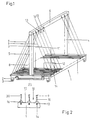
Die Vorrichtung besteht aus einer Bodenplatte 1, die an ihrer
Unterseite Füße 2 aufweist. Die Füße 2 können, so wie in der
Zeichnung gezeigt, mit Rollen 3 bestückt sein, wobei wenigstens
ein Teil der Rollen 3 als Lenkrollen ausgebildet sein
kann. Die Vorrichtung ist dann ein sogenannter "Fächerwagen". The device consists of a
Von der Bodenplatte 1 ragen Steher 4 und 5 nach oben und tragen
an ihren oberen Enden einen Balken 6.
Zwischen den Längsrändern 7 und 8 der Bodenplatte 1 und dem
Balken 6 sind stab- oder schnurartige Elemente 9 gespannt, die
zwischen sich jeweils ein Fach 10 bilden, in das tafelförmige
Gegenstände 11, 12 eingeschoben werden können. Über die stab- oder
schnurartigen Elemente 9 sind in den Fig. 1 und 3 nicht
dargestellte Rohrstücke 30 gesteckt, die weiter unten näher
beschrieben werden.Between the
Es ist auch eine Ausführungsform möglich, bei der die stab- oder
schnurartigen Elemente 9 vom Balken 6 nur nach einer
Seite, d.h. zum Längsrand 7 oder 8 der Bodenplatte 1 gespannt
sind. Bei dieser Ausführungsform sind die Steher 4 und 5 bevorzugt
an einem der Längsränder der Bodenplatte 1, d.h. in
zwei Ecken derselben angeordnet.An embodiment is also possible in which the rod or
cord-
Die stab- oder schnurartigen Elemente 9 sind beispielsweise
Stahlseile, über welche die Rohrstücke 30 geschoben sind, die
in Fig. 4 und 5 näher dargestellt sind. Um die nötige Spannung
der stab- oder schnurartigen Elemente 9 zu gewährleisten,
können, wie dies an sich aus der EP-A- 477 613 bekannt ist, an
einem oder an beiden Enden der Elemente 9 kurze Federn 13
vorgesehen sein, die mit Hilfe von Muttern 14 gespannt werden
können, um die Elemente vorzuspannen (Fig. 2).The rod-like or cord-
Im Bereich jedes Faches 10 sind in der Oberseite der Bodenplatte
1 Nuten 15 vorgesehen, die beidseits von Leisten 16
begrenzt werden, die z.B. auf der Bodenplatte 1 angeschraubt
oder mit ihr einstückig ausgebildet sind. Dabei sind die Nuten
15 etwas schmäler als die von den stab- oder schnurförmigen
Elementen 9 bestimmte Breite der Fächer 10, so daß sich eine
Führung der einzuschiebenden plattenförmigen Gegenstände 11,
12 ergibt und diese nicht an in benachbarten Fächern 10 abgestellten
Gegenständen 11, 12 entlangschleifen können. Weiters
sorgen die Nuten 15 dafür, daß in den Fächern 10 abgestellte
tafelförmige Gegenstände 11, 12 nur im Bereich ihrer oberen
Kante an dem einen oder anderen stab- oder schnurförmigen
Element 9, das ein Fach 10 begrenzt, anliegen. In the area of each
Durch die Schrägstellung der stab- oder schnurförmigen Elemente
9, welche die Fächer 10 begrenzen, genügen je Fach 10 zwei
stab- oder schnurförmige Elemente 9, um auch das sichere Abstellen
von Gegenständen 11, 12 mit unterschiedlicher Höhe
(senkrecht zur Bodenplatte 1 gemessene Erstreckung der abzustellenden
Gegenstände) sicher zu halten.Due to the inclination of the rod or cord-
Wie aus Fig. 1 und 3 ersichtlich, sind in der Bodenplatte 1
quer zu den Nuten 15 verlaufende, nach unten offene Ausnehmungen
17 vorgesehen, in welchen Transportwalzen 18 aufgenommen
sind. Dabei können auch in den Leisten 16 an ihrer der Bodenplatte
1 zugewandten Seite 20 Ausnehmungen 19 vorgesehen sein,
die über den quer zu den Nuten 15 verlaufenden Ausnehmungen 17
in der Bodenplatte 1 angeordnet sind. Die Ausnehmungen 19 in
den Leisten 16 sind so tief, daß die Transportwalzen 18 so
weit hochgehoben werden können, daß sie in die Nuten 15 ragen
und somit die tafelförmigen Gegenstände 11, 12 in die oder aus
den Fächern 10 fördern können.1 and 3, 1 are in the base plate
Recesses running transversely to the
Die Transportwalzen 18 sind im dargestellten Ausführungsbeispiel
an einem Rahmen 25 befestigt, der entweder starr an der
Bodenplatte 1 befestigt ist, jedoch bevorzugt z.B. über Druckmittelzylinder
relativ zur Bodenplatte 1 verstellbar ist, so
daß die Transportwalzen 18 außer Eingriff mit den in den Fächern
10 aufgenommenen tafelförmigen Gegenständen 11, 12 gebracht
werden können.The
Bei dem in Fig. 1 dargestellten Ausführungsbeispiel ist der
Rahmen 25, in dem die Transportwalzen 18 gelagert sind, an der
Bodenplatte 1 angeordnet.In the embodiment shown in Fig. 1 is the
In Fig. 3 ist der Rahmen 25 auf nicht dargestellte Weise an
einem Grundrahmen 26 angeordnet und gegebenenfalls, z.B. über
Druckmittelzylinder, heb- und senkbar. Die Vorrichtung steht
mit Füßen 28 auf dem Grundrahmen. Der Grundrahmen 26 weist
Laufrollen 27 auf, von denen wenigstens ein Paar als Lenkrollen
ausgebildet sein kann. Auf diese Weise ist die Vorrichtung
mit den Fächern 10 entweder für sich alleine (Fig. 1) oder
über den Grundrahmen 26 (Fig. 3) verfahrbar und kann gegenüber
einer vorgelagerten Fördereinrichtung, aber beispielsweise
auch gegenüber einem weiteren, hinter dem Fächerwagen angeordneten
Fächerwagen positioniert werden, so daß z.B. Glastafelzuschnitte
nach beliebigen Ordnungskriterien in hintereinander
angeordneten Fächerwagen sortiert werden können, wie dies an
sich aus der EP-A-477 163 bekannt ist.In Fig. 3 the
In den Fig. 4 und 5 ist ein stab- oder schnurartiges Element 9
mit darüber geschobenen, zylinderförmigen Rohrstücken 30, die
in den Fig. 1 und 3 nicht eingezeichnet wurden, in vergrößertem
Maßstab dargestellt. Die Rohrstücke 30 weisen die Form
einer Rohrhülse mit einer Bohrung 31 und einem zylinderförmigen
Außenmantel 32 auf und liegen über zu ihrer Längsachse
senkrecht ausgerichtete Stirnflächen 33 lose aneinander an.
Die Rohrstücke 30 sind vorzugsweise aus Kunststoff hergestellt.4 and 5 is a rod or cord-
Das unterste Rohrstück 30 liegt, wie in Fig. 2 und 4 dargestellt
ist, auf der Leiste 16 auf und das oberste Rohrstück 30
ist vom Balken 6 bzw. den Federn 13 wenigstens so weit beabstandet,
wie der Hub des Rahmens 25 beträgt.The
Stößt bzw. liegt eine Glastafel beim Hinein- oder Herausschieben
an einem Rohrstück 30 an, so kann sich dieses frei auf
seinem stab- oder schnurartigen Element 9 drehen, so daß es an
der Glastafel abrollt und von diesem nicht aufgeschnitten oder
sonst beschädigt wird.A glass panel bumps or lies when it is pushed in or out
on a piece of
Wird eine Glastafel vom Rahmen 25 hochgehoben, während sie
beispielsweise geringfügig gegenüber dem Stahlseil 9 geneigt
mit ihrer oberen Längskante an einem Rohrstück 30 anliegt,
dann wird dieses Rohrstück 30 sowie die darüber befindlichen
Rohrstücke 30 ebenfalls nach oben geschoben, ohne daß es zu
einer die Rohrstücke 30 beschädigenden Relativbewegung zwischen
diesen und der Glastafel kommt und ohne daß die Hubbewegung
der Glastafel behindert wird.A glass sheet is lifted off the
Durch die Erfindung wird somit eine Möglichkeit zur Verfügung gestellt, den direkten Kontakt zwischen den platten- oder tafelförmigen Gegenständen, wie Glastafeln oder Isolierglasscheiben, und den seitlichen Abstützungen mit gespannten stab- oder oder schnurartigen Elementen, beispielsweise Stahlseilen, zu verhindern, ohne daß es zu einer unnötigen Platzvergeudung oder einer Behinderung der Hubbewegung der Gegenstände wie gemäß der EP-A-477 163 oder zu einem sehr hohen Verschleiß der Kunststoffüberzüge wie bei der EP-A-603 151 kommt.The invention thus makes one possibility available put the direct contact between the plate or tabular objects, such as glass panels or insulating glass panes, and the side supports with tensioned rod or or cord-like elements, for example steel cables prevent without unnecessary waste of space or an obstacle to the lifting movement of the objects such as according to EP-A-477 163 or to a very high wear of the Plastic covers like the one in EP-A-603 151.
Zusammenfassend kann ein Ausführungsbeispiel der Erfindung wie folgt dargestellt werden:In summary, an embodiment of the invention can be like are represented as follows:
Eine Vorrichtung zum Lagern von tafel- oder plattenförmigen
Gegenständen 11, 12, wie Glastafeln oder Isolierglasscheiben,
weist mehrere etwa vertikal ausgerichtete Fächer 10 zur Aufnahme
der Gegenstände 11, 12 auf, wobei die Fächer 10 von
seitlichen Abstützungen in Form von gespannten stab- oder
schnurartigen Elementen 9 begrenzt werden. Um den direkten
Kontakt zwischen den Gegenständen 11, 12 und den stab- oder
schnurartigen Elementen 9, beispielsweise Stahlseilen, zu
vermeiden, sind über die stab- oder schnurartigen Elemente 9
mehrere voneinander getrennte, lose aneinander anliegende,
zylinderförmige Rohrstücke 30
gesteckt, die gegenüber den stab- oder schnurartigen Elementen
9 verdrehbar sind. Die Rohrstücke 30 sind gegenüber den stab- oder
schnurartigen Elementen 9 in deren Längsrichtung verschiebbar
und zwischen dem obersten Rohrstück 30 auf jedem
stab- oder schnurartigen Element 9 und der Halterung 6 der
oberen Enden der stab- oder schnurartigen Elemente 9 ist ein
Abstand vorgesehen, in dem keine Rohrstücke 30 vorgesehen
sind. Dadurch können die Rohrstücke 30 bei einer Horizontalbewegung
der Gegenstände 11, 12 an diesen abrollen und bei einer
Vertikalbewegung mitgleiten, so daß sie durch diese Bewegungen
nicht beschädigt werden.A device for storing table or plate-
Claims (4)
- Device for storing panel- or pane-shaped articles (11), such a glass plates or insulating glass panes, with a plurality of roughly vertically-aligned compartments (10) for receiving the articles (11), the compartments (10) being defined by lateral supports in the form of tensioned rod- or cord-like elements (9) upon which are disposed freely rotatable rollers (30), characterised in that the rollers are cylindrical pipe sections (30) pushed over the rod- or cord-like elements (9), and which bear loosely against one another via their end faces (33) aligned vertically to the axis of the rod- or cord-like elements (9).
- Device according to claim 1, characterised in that the pipe sections (30) are displaceable relative to the rod- or cord-like elements (9), in their longitudinal direction.
- Device according to claim 1 or 2, characterised in that there is provided, between the uppermost pipe section (30) on each rod- or cord-like elements (9), and a retaining means (6) of the upper end of the rod-or cord-like elements (9), an area in which no pipe sections (30) are provided.
- Device according to one of claims 1 to 3, characterised in that the pipe sections (30) consist of plastics.
Applications Claiming Priority (2)
| Application Number | Priority Date | Filing Date | Title |
|---|---|---|---|
| AT0183794A AT401258B (en) | 1994-09-27 | 1994-09-27 | DEVICE FOR STORING GLASS PANELS OR INSULATING GLASS |
| AT1837/94 | 1994-09-27 |
Publications (2)
| Publication Number | Publication Date |
|---|---|
| EP0704389A1 EP0704389A1 (en) | 1996-04-03 |
| EP0704389B1 true EP0704389B1 (en) | 1998-11-18 |
Family
ID=3522092
Family Applications (1)
| Application Number | Title | Priority Date | Filing Date |
|---|---|---|---|
| EP95890160A Expired - Lifetime EP0704389B1 (en) | 1994-09-27 | 1995-09-11 | Device for storing glassplates or insulating glasspanes |
Country Status (6)
| Country | Link |
|---|---|
| US (1) | US5685437A (en) |
| EP (1) | EP0704389B1 (en) |
| AT (2) | AT401258B (en) |
| DE (3) | DE59504251D1 (en) |
| ES (1) | ES2124989T3 (en) |
| IT (1) | IT237170Y1 (en) |
Families Citing this family (18)
| Publication number | Priority date | Publication date | Assignee | Title |
|---|---|---|---|---|
| EP0827489A1 (en) * | 1996-03-21 | 1998-03-11 | Peter Lisec | Process and plant for hardening glass plates |
| ATE190032T1 (en) * | 1996-04-05 | 2000-03-15 | Cardinal Ig Co | PACKAGING FOR PLATES SUCH AS GLASS PANELS |
| US6588605B1 (en) | 2002-01-30 | 2003-07-08 | Cardinal Cg Company | Planar article rack having closeable holding members |
| US20030196971A1 (en) | 2002-04-19 | 2003-10-23 | Jeskey Marion Michael | Foldable transport rack and methods of use thereof |
| US20050067360A1 (en) * | 2003-09-30 | 2005-03-31 | Darvial Mickey James | Racking systems and related methods |
| US20060043032A1 (en) * | 2004-09-01 | 2006-03-02 | Mchugh Michael P | Modular rack and system of use |
| US7182559B1 (en) | 2006-06-30 | 2007-02-27 | C.G. Industrial Equipment Inc. | Rack for holding plate glass and other planar articles |
| US20110239838A1 (en) * | 2009-10-07 | 2011-10-06 | Hp3 Software, Inc. | Insulated glass line having a dynamic batchless direct feed cutter |
| AT11889U1 (en) | 2009-10-22 | 2011-06-15 | Inova Lisec Technologiezentrum | DEVICE FOR APPLYING DISTANCE HOLDERS ON GLASS PANES |
| CN103662377A (en) * | 2012-08-31 | 2014-03-26 | 昆山冠益玻璃有限公司 | Glass transportation frame, |
| RU2597033C1 (en) | 2013-01-28 | 2016-09-10 | Лисец Аустриа Гмбх | Device with turntable sections |
| BE1021416B1 (en) * | 2013-03-26 | 2015-11-18 | Parnass, Besloten Vennootschap Met Beperkte Aansprakelijkheid | ELEMENT FOR STORING, HANDLING AND TRANSPORTING MAINLY PLATE-MADE ITEMS |
| US9340373B2 (en) | 2013-12-12 | 2016-05-17 | Integrated Automation Systems, Llc | Stackable insulated glass slat rack |
| US9951553B2 (en) | 2014-06-05 | 2018-04-24 | Erdman Automation Corporation | High speed parallel process insulated glass manufacturing line |
| DE202014103799U1 (en) * | 2014-08-15 | 2015-11-17 | Carsten Böttcher | Transport and / or storage rack and arrangement of a transport and / or storage rack on a base plate |
| JP6300100B2 (en) * | 2014-08-19 | 2018-03-28 | 日本電気硝子株式会社 | Glass plate holding jig and method for producing chemically strengthened glass plate |
| US10253552B2 (en) | 2016-04-21 | 2019-04-09 | Erdman Automation Corporation | High speed parallel process insulated glass manufacturing line |
| DE102018207812A1 (en) * | 2018-05-17 | 2019-11-21 | Hegla Gmbh & Co. Kg | Storage device for storing glass panels, preferably laminated glass panels or single-pane safety glass panels |
Citations (2)
| Publication number | Priority date | Publication date | Assignee | Title |
|---|---|---|---|---|
| EP0477163A1 (en) * | 1990-09-18 | 1992-03-25 | Peter Lisec | Device for sorting sized glass sheets |
| WO1995025688A1 (en) * | 1994-03-24 | 1995-09-28 | Peter Lisec | Method and device for sorting blanks |
Family Cites Families (13)
| Publication number | Priority date | Publication date | Assignee | Title |
|---|---|---|---|---|
| US2005099A (en) * | 1933-07-07 | 1935-06-18 | Pittsburgh Plate Glass Co | Glass rack |
| US2518624A (en) * | 1946-10-11 | 1950-08-15 | Kraft Louis | Rack structure for glaziers' vehicles |
| US2681233A (en) * | 1951-09-19 | 1954-06-15 | William C Smith | Rack for removing glass case fronts |
| US2940402A (en) * | 1953-10-23 | 1960-06-14 | Libbey Owens Ford Glass Co | Railroad cars for transporting sheets or plates |
| SE345430B (en) * | 1970-04-08 | 1972-05-29 | Emmaboda Glasverk Ab | |
| CA972005A (en) * | 1972-07-12 | 1975-07-29 | Erste Deutsche Floatglas G.M.B.H. And Co. | Carrying frame for giant glass sheets |
| FR2534243B1 (en) * | 1982-10-11 | 1986-02-14 | Saint Gobain Vitrage | PROCESS FOR THE TRANSPORT OF GLASS SHEETS CARRIED TO THEIR DEFORMATION TEMPERATURE, ITS APPLICATION TO BOMBING AND DEVICE FOR ITS IMPLEMENTATION |
| NL8600734A (en) * | 1986-03-21 | 1987-10-16 | Capelleveen Bv Geb | TRANSPORTER. |
| US4904112A (en) * | 1989-07-26 | 1990-02-27 | Mcdonald Carroll W | Underground irrigation system |
| DE4030222C1 (en) * | 1990-09-25 | 1991-11-14 | Vegla Vereinigte Glaswerke Gmbh, 5100 Aachen, De | |
| DE59107277D1 (en) | 1990-09-27 | 1996-02-29 | Siemens Ag | Method for the uniform selection of events occurring in a communication system |
| IT1258617B (en) * | 1992-09-18 | 1996-02-27 | ORTHOGONAL TRANSLATION MOBILE FRAME WAREHOUSE FOR FLAT-SHAPED PRODUCTS | |
| AT398302B (en) | 1992-12-14 | 1994-11-25 | Lisec Peter | DEVICE FOR STORING TABLE OR PLATE-SHAPED OBJECTS |
-
1994
- 1994-09-27 AT AT0183794A patent/AT401258B/en not_active IP Right Cessation
-
1995
- 1995-09-11 DE DE59504251T patent/DE59504251D1/en not_active Expired - Lifetime
- 1995-09-11 AT AT95890160T patent/ATE173445T1/en not_active IP Right Cessation
- 1995-09-11 EP EP95890160A patent/EP0704389B1/en not_active Expired - Lifetime
- 1995-09-11 ES ES95890160T patent/ES2124989T3/en not_active Expired - Lifetime
- 1995-09-14 DE DE19534175A patent/DE19534175C2/en not_active Expired - Fee Related
- 1995-09-14 DE DE29514820U patent/DE29514820U1/en not_active Expired - Lifetime
- 1995-09-20 US US08/530,903 patent/US5685437A/en not_active Expired - Lifetime
- 1995-09-25 IT IT1995MI000650U patent/IT237170Y1/en active IP Right Grant
Patent Citations (2)
| Publication number | Priority date | Publication date | Assignee | Title |
|---|---|---|---|---|
| EP0477163A1 (en) * | 1990-09-18 | 1992-03-25 | Peter Lisec | Device for sorting sized glass sheets |
| WO1995025688A1 (en) * | 1994-03-24 | 1995-09-28 | Peter Lisec | Method and device for sorting blanks |
Also Published As
| Publication number | Publication date |
|---|---|
| ITMI950650U1 (en) | 1997-03-25 |
| AT401258B (en) | 1996-07-25 |
| ATA183794A (en) | 1995-12-15 |
| ES2124989T3 (en) | 1999-02-16 |
| DE19534175A1 (en) | 1996-03-28 |
| IT237170Y1 (en) | 2000-08-31 |
| DE29514820U1 (en) | 1995-11-09 |
| DE19534175C2 (en) | 1997-12-04 |
| US5685437A (en) | 1997-11-11 |
| DE59504251D1 (en) | 1998-12-24 |
| ITMI950650V0 (en) | 1995-09-25 |
| EP0704389A1 (en) | 1996-04-03 |
| ATE173445T1 (en) | 1998-12-15 |
Similar Documents
| Publication | Publication Date | Title |
|---|---|---|
| EP0704389B1 (en) | Device for storing glassplates or insulating glasspanes | |
| EP0770756B1 (en) | Device for moving sheets of insulating glazings | |
| AT402194B (en) | METHOD AND SYSTEM FOR SORTING CUTS | |
| EP0603151B1 (en) | Device with partitions | |
| DE4321314C2 (en) | Device for loading and / or unloading containers | |
| DE3619096A1 (en) | DEVICE FOR HOLDING AND TRANSPORTING MOLDED PARTS | |
| DE3529514C1 (en) | Clip chain conveyor for tension clips with roller bearings in tension frames for the continuous treatment of a material web | |
| DE3026746C2 (en) | ||
| EP0462609A1 (en) | Cover for elongated servicing pits | |
| EP3793921B1 (en) | Storage device for storing glass panes, preferably laminated glass panes or tempered glass panes | |
| AT402196B (en) | DEVICE FOR STACKING PLATE-SHAPED FORMAT CUTTINGS AND FOR REMOVING THE STACK formed from the FORMAT CUTTINGS | |
| DE2927748C2 (en) | Movable telescopic grandstand | |
| DE3624848C1 (en) | Vehicle for transporting goods in containers | |
| DE3712104C2 (en) | ||
| EP1484267A2 (en) | Accumulating conveyor with carrier | |
| EP1037789B1 (en) | Shopping cart | |
| DE4306764C1 (en) | Laminating press with rams and work-support - has parallel plates of supporting frame fixed together at one side and with support and guide rail at other | |
| DE8326343U1 (en) | Pallet for transport and storage of roll goods | |
| EP0397133A2 (en) | Device for changing the position of rolls of wound web-material | |
| DE7919671U1 (en) | TRAVELABLE TELESCOPIC RULE | |
| DE10223599A1 (en) | Container for transporting objects on uneven terrain, has side rollers and guiding track with diagonal braces | |
| DE19824368A1 (en) | Stackable shopping trolley which does not require tubular frame. | |
| DE2822561A1 (en) | Storage system for semi-finished parts - uses rectangular frames accommodating largest items fitting in rack | |
| EP1285856A2 (en) | Device for storage and transport of slabs | |
| DE7814235U1 (en) | SALES STAND FOR DOORS |
Legal Events
| Date | Code | Title | Description |
|---|---|---|---|
| PUAI | Public reference made under article 153(3) epc to a published international application that has entered the european phase |
Free format text: ORIGINAL CODE: 0009012 |
|
| AK | Designated contracting states |
Kind code of ref document: A1 Designated state(s): AT BE CH DE DK ES FR GB GR IE IT LI LU MC NL PT SE |
|
| 17P | Request for examination filed |
Effective date: 19960224 |
|
| 17Q | First examination report despatched |
Effective date: 19970225 |
|
| GRAG | Despatch of communication of intention to grant |
Free format text: ORIGINAL CODE: EPIDOS AGRA |
|
| GRAG | Despatch of communication of intention to grant |
Free format text: ORIGINAL CODE: EPIDOS AGRA |
|
| GRAG | Despatch of communication of intention to grant |
Free format text: ORIGINAL CODE: EPIDOS AGRA |
|
| GRAH | Despatch of communication of intention to grant a patent |
Free format text: ORIGINAL CODE: EPIDOS IGRA |
|
| GRAH | Despatch of communication of intention to grant a patent |
Free format text: ORIGINAL CODE: EPIDOS IGRA |
|
| GRAA | (expected) grant |
Free format text: ORIGINAL CODE: 0009210 |
|
| AK | Designated contracting states |
Kind code of ref document: B1 Designated state(s): AT BE CH DE DK ES FR GB GR IE IT LI LU MC NL PT SE |
|
| PG25 | Lapsed in a contracting state [announced via postgrant information from national office to epo] |
Ref country code: NL Free format text: LAPSE BECAUSE OF FAILURE TO SUBMIT A TRANSLATION OF THE DESCRIPTION OR TO PAY THE FEE WITHIN THE PRESCRIBED TIME-LIMIT Effective date: 19981118 Ref country code: GR Free format text: LAPSE BECAUSE OF NON-PAYMENT OF DUE FEES Effective date: 19981118 |
|
| REF | Corresponds to: |
Ref document number: 173445 Country of ref document: AT Date of ref document: 19981215 Kind code of ref document: T |
|
| REG | Reference to a national code |
Ref country code: CH Ref legal event code: NV Representative=s name: TROESCH SCHEIDEGGER WERNER AG Ref country code: CH Ref legal event code: EP |
|
| ET | Fr: translation filed | ||
| REF | Corresponds to: |
Ref document number: 59504251 Country of ref document: DE Date of ref document: 19981224 |
|
| REG | Reference to a national code |
Ref country code: IE Ref legal event code: FG4D Free format text: GERMAN |
|
| GBT | Gb: translation of ep patent filed (gb section 77(6)(a)/1977) |
Effective date: 19990119 |
|
| ITF | It: translation for a ep patent filed |
Owner name: RACHELI & C. S.R.L. |
|
| REG | Reference to a national code |
Ref country code: ES Ref legal event code: FG2A Ref document number: 2124989 Country of ref document: ES Kind code of ref document: T3 |
|
| PG25 | Lapsed in a contracting state [announced via postgrant information from national office to epo] |
Ref country code: PT Free format text: LAPSE BECAUSE OF FAILURE TO SUBMIT A TRANSLATION OF THE DESCRIPTION OR TO PAY THE FEE WITHIN THE PRESCRIBED TIME-LIMIT Effective date: 19990218 Ref country code: DK Free format text: LAPSE BECAUSE OF FAILURE TO SUBMIT A TRANSLATION OF THE DESCRIPTION OR TO PAY THE FEE WITHIN THE PRESCRIBED TIME-LIMIT Effective date: 19990218 |
|
| NLV1 | Nl: lapsed or annulled due to failure to fulfill the requirements of art. 29p and 29m of the patents act | ||
| PG25 | Lapsed in a contracting state [announced via postgrant information from national office to epo] |
Ref country code: IE Free format text: LAPSE BECAUSE OF NON-PAYMENT OF DUE FEES Effective date: 19990820 |
|
| PG25 | Lapsed in a contracting state [announced via postgrant information from national office to epo] |
Ref country code: LU Free format text: LAPSE BECAUSE OF NON-PAYMENT OF DUE FEES Effective date: 19990911 |
|
| PLBE | No opposition filed within time limit |
Free format text: ORIGINAL CODE: 0009261 |
|
| STAA | Information on the status of an ep patent application or granted ep patent |
Free format text: STATUS: NO OPPOSITION FILED WITHIN TIME LIMIT |
|
| REG | Reference to a national code |
Ref country code: IE Ref legal event code: FD4D |
|
| 26N | No opposition filed | ||
| PG25 | Lapsed in a contracting state [announced via postgrant information from national office to epo] |
Ref country code: MC Free format text: LAPSE BECAUSE OF NON-PAYMENT OF DUE FEES Effective date: 20000331 |
|
| REG | Reference to a national code |
Ref country code: GB Ref legal event code: IF02 |
|
| REG | Reference to a national code |
Ref country code: GB Ref legal event code: 732E |
|
| PGFP | Annual fee paid to national office [announced via postgrant information from national office to epo] |
Ref country code: SE Payment date: 20030908 Year of fee payment: 9 |
|
| PGFP | Annual fee paid to national office [announced via postgrant information from national office to epo] |
Ref country code: BE Payment date: 20030912 Year of fee payment: 9 |
|
| PGFP | Annual fee paid to national office [announced via postgrant information from national office to epo] |
Ref country code: AT Payment date: 20030922 Year of fee payment: 9 |
|
| REG | Reference to a national code |
Ref country code: FR Ref legal event code: TP |
|
| PG25 | Lapsed in a contracting state [announced via postgrant information from national office to epo] |
Ref country code: AT Free format text: LAPSE BECAUSE OF NON-PAYMENT OF DUE FEES Effective date: 20040911 |
|
| PG25 | Lapsed in a contracting state [announced via postgrant information from national office to epo] |
Ref country code: SE Free format text: LAPSE BECAUSE OF NON-PAYMENT OF DUE FEES Effective date: 20040912 |
|
| PG25 | Lapsed in a contracting state [announced via postgrant information from national office to epo] |
Ref country code: BE Free format text: LAPSE BECAUSE OF NON-PAYMENT OF DUE FEES Effective date: 20040930 |
|
| BERE | Be: lapsed |
Owner name: *LISEC PETER Effective date: 20040930 |
|
| EUG | Se: european patent has lapsed | ||
| BERE | Be: lapsed |
Owner name: *LISEC PETER Effective date: 20040930 |
|
| REG | Reference to a national code |
Ref country code: DE Ref legal event code: R082 Ref document number: 59504251 Country of ref document: DE Representative=s name: PATENTANWAELTE HENKEL, BREUER & PARTNER, DE |
|
| PGFP | Annual fee paid to national office [announced via postgrant information from national office to epo] |
Ref country code: DE Payment date: 20140922 Year of fee payment: 20 Ref country code: CH Payment date: 20140919 Year of fee payment: 20 |
|
| PGFP | Annual fee paid to national office [announced via postgrant information from national office to epo] |
Ref country code: ES Payment date: 20140926 Year of fee payment: 20 Ref country code: GB Payment date: 20140919 Year of fee payment: 20 Ref country code: FR Payment date: 20140919 Year of fee payment: 20 |
|
| PGFP | Annual fee paid to national office [announced via postgrant information from national office to epo] |
Ref country code: IT Payment date: 20140929 Year of fee payment: 20 |
|
| REG | Reference to a national code |
Ref country code: DE Ref legal event code: R071 Ref document number: 59504251 Country of ref document: DE |
|
| REG | Reference to a national code |
Ref country code: CH Ref legal event code: PL |
|
| REG | Reference to a national code |
Ref country code: GB Ref legal event code: PE20 Expiry date: 20150910 |
|
| PG25 | Lapsed in a contracting state [announced via postgrant information from national office to epo] |
Ref country code: GB Free format text: LAPSE BECAUSE OF EXPIRATION OF PROTECTION Effective date: 20150910 |
|
| REG | Reference to a national code |
Ref country code: ES Ref legal event code: FD2A Effective date: 20151229 |
|
| PG25 | Lapsed in a contracting state [announced via postgrant information from national office to epo] |
Ref country code: ES Free format text: LAPSE BECAUSE OF EXPIRATION OF PROTECTION Effective date: 20150912 |