EP0703588A1 - Bobine d'allumage - Google Patents
Bobine d'allumage Download PDFInfo
- Publication number
- EP0703588A1 EP0703588A1 EP95115090A EP95115090A EP0703588A1 EP 0703588 A1 EP0703588 A1 EP 0703588A1 EP 95115090 A EP95115090 A EP 95115090A EP 95115090 A EP95115090 A EP 95115090A EP 0703588 A1 EP0703588 A1 EP 0703588A1
- Authority
- EP
- European Patent Office
- Prior art keywords
- coil
- case
- ignition coil
- iron core
- spool
- Prior art date
- Legal status (The legal status is an assumption and is not a legal conclusion. Google has not performed a legal analysis and makes no representation as to the accuracy of the status listed.)
- Withdrawn
Links
Images


Classifications
-
- H—ELECTRICITY
- H01—ELECTRIC ELEMENTS
- H01F—MAGNETS; INDUCTANCES; TRANSFORMERS; SELECTION OF MATERIALS FOR THEIR MAGNETIC PROPERTIES
- H01F5/00—Coils
-
- H—ELECTRICITY
- H01—ELECTRIC ELEMENTS
- H01F—MAGNETS; INDUCTANCES; TRANSFORMERS; SELECTION OF MATERIALS FOR THEIR MAGNETIC PROPERTIES
- H01F38/00—Adaptations of transformers or inductances for specific applications or functions
- H01F38/12—Ignition, e.g. for IC engines
-
- H—ELECTRICITY
- H01—ELECTRIC ELEMENTS
- H01F—MAGNETS; INDUCTANCES; TRANSFORMERS; SELECTION OF MATERIALS FOR THEIR MAGNETIC PROPERTIES
- H01F27/00—Details of transformers or inductances, in general
- H01F27/02—Casings
-
- H—ELECTRICITY
- H01—ELECTRIC ELEMENTS
- H01F—MAGNETS; INDUCTANCES; TRANSFORMERS; SELECTION OF MATERIALS FOR THEIR MAGNETIC PROPERTIES
- H01F27/00—Details of transformers or inductances, in general
- H01F27/24—Magnetic cores
- H01F27/26—Fastening parts of the core together; Fastening or mounting the core on casing or support
- H01F27/266—Fastening or mounting the core on casing or support
-
- H—ELECTRICITY
- H01—ELECTRIC ELEMENTS
- H01F—MAGNETS; INDUCTANCES; TRANSFORMERS; SELECTION OF MATERIALS FOR THEIR MAGNETIC PROPERTIES
- H01F27/00—Details of transformers or inductances, in general
- H01F27/28—Coils; Windings; Conductive connections
- H01F27/32—Insulating of coils, windings, or parts thereof
- H01F27/324—Insulation between coil and core, between different winding sections, around the coil; Other insulation structures
- H01F27/325—Coil bobbins
-
- H—ELECTRICITY
- H01—ELECTRIC ELEMENTS
- H01F—MAGNETS; INDUCTANCES; TRANSFORMERS; SELECTION OF MATERIALS FOR THEIR MAGNETIC PROPERTIES
- H01F5/00—Coils
- H01F5/02—Coils wound on non-magnetic supports, e.g. formers
- H01F2005/025—Coils wound on non-magnetic supports, e.g. formers wound on coaxial arrangement of two or more formers
-
- H—ELECTRICITY
- H01—ELECTRIC ELEMENTS
- H01F—MAGNETS; INDUCTANCES; TRANSFORMERS; SELECTION OF MATERIALS FOR THEIR MAGNETIC PROPERTIES
- H01F38/00—Adaptations of transformers or inductances for specific applications or functions
- H01F38/12—Ignition, e.g. for IC engines
- H01F2038/122—Ignition, e.g. for IC engines with rod-shaped core
-
- H—ELECTRICITY
- H01—ELECTRIC ELEMENTS
- H01F—MAGNETS; INDUCTANCES; TRANSFORMERS; SELECTION OF MATERIALS FOR THEIR MAGNETIC PROPERTIES
- H01F38/00—Adaptations of transformers or inductances for specific applications or functions
- H01F38/12—Ignition, e.g. for IC engines
- H01F2038/125—Ignition, e.g. for IC engines with oil insulation
Definitions
- the present invention relates to an ignition coil for supplying high tension electric voltage to spark plugs for an internal combustion engine.
- a common conventional ignition coil has a center iron core, and a primary coil and a secondary coil are wound around the center iron core.
- the center iron core is usually a closed magnetic circuit type which prevents magnetic flux from leaking out.
- Such iron core is sometimes provided with a small gap and/or a permanent magnet connected in series therewith.
- the ignition coil may be mounted on an engine, a spark plug or another place according to circumstances.
- U. S. Patent 5,101,803 (which corresponds to Japanese Unexamined Patent Publication Hei 3-154311) patented to the same assignee of this application discloses an ignition coil which is mounted on a spark plug directly.
- the ignition coil disclosed in U. S. Patent 5,101,803 needs complicated manufacturing steps because permanent magnets and other members are disposed in its magnetic circuit. Insulating oil filled in its case may not cover entire portions where high tension voltage is applied when the ignition coil is mounted, for instance, on a V-engine with an inclination angle. Thus, the dielectric strength of the ignition coil decreases especially that between the central core and a portion of the primary coil and engine troubles may be expected.
- U. S. Patent 4,617,907 (which corresponds to Japanese National Publication of PCT Application Sho 60-501961) discloses an ignition coil which has a case accommodating a primary coil, a secondary coil and insulating oil.
- the insulating oil is filled through a small opening at a bottom portion of the case after the coils are inserted in the case from an upper open end of the case which is thereafter sealed with thermosetting resin.
- the present invention is made in view of the above mentioned circumstances, and has a main object of providing an improved ignition coil which has a simple structure and high reliability.
- Another object of the present invention is to provide an improved ignition coil which has a pair of spools and an iron core unit with magnets retained automatically by the spools when assembled together.
- a further object of the present invention is to provide an improved ignition coil which has a plurality of magnetic members, a primary coil, a secondary coil and their spools soaked in insulating oil therein.
- a still further object of the present invention is to provide an ignition coil which has means to increase the creepage distance between the magnetic members and the primary coil.
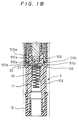
- Figs. 1A and 1B illustrate an ignition coil according to a first embodiment of the present invention.
- Fig. 1A shows an upper portion of the ignition coil and
- Fig.1B shows the other portion thereof.
- the ignition coil is mounted to an engine head cover or cylinder head and connected directly to a spark plug installed to an engine as disclosed in U. S. Patent 5,101,803.
- a case 100 is made of a resinous insulating material and has a connector member 3 to be connected to a plug (not shown).
- the case 100 is generally cylindrical, however it may be polygonal.
- a transformer unit 5 and a primary current switching circuit 7 are disposed in the inside 102 of the case 100, and an input signal connector 9 and a bracket 11 are formed on an upper portion of the case 100.
- the bracket 11 is to be fixed to a head cover of an engine by a bolt or the like (not shown).
- a cylindrical portion 104 is formed in the connector member 3 to hold the spark plug, and a plug cap 13 made of rubber is fitted to the open end of the cylindrical portion 104.
- a conductive metal cup 15 is insert-molded into a bottom of the cylindrical portion 104 to divide the inside 102 of the case and the cylindrical portion 104 hermetically.
- a bottom portion of the case has an annular ring which is slightly greater in diameter than the rest so that it may not fall out from the cylinder portion 104.
- a coil spring 17 is disposed in the cylindrical portion and its one coil end is held within the annular ring of the metal cup 15. When the cylindrical portion 104 is placed on a spark plug, the coil spring 17 makes electric contact with the spark plug by itself.
- a step portion 106 is formed at the inside 102 of the case 100 adjacent to the cup 15.
- the input signal connector 9 is formed integrally with the case 100 along with three connector pins 19 which are insert-molded therein and extending through the case 100.
- the bracket 11 is formed integrally with the case 100 with a metal collar 21 insert-molded therein.
- a cover 23 made of resinous material is disposed on an upper end of the case 100.
- An annular groove 108 is formed on the upper end of the case 100 to receive an O-ring 25, with which a gap between the case 100 and the cover 23 is sealed hermetically.
- the transformer unit 5 in the inside 102 of the case 100 has an iron core 502, permanent magnets 504 and 506, and an auxiliary core 508.
- the iron core 502 is a stack of low iron-loss silicon steel plates.
- the permanent magnets 504 and 506 are magnetized in a direction opposite the magnetic flux generated by a primary coil 516 (to be described later) of the transformer when energized and are respectively fixed to both ends of the iron core 502 by adhesive tapes (not shown).
- the transformer unit 5 also has a secondary coil spool (hereinafter referred to as the secondary spool) 510, a secondary coil 512 wound around the secondary spool 510, a primary coil spool (hereinafter referred to as the primary spool) 514 and the primary coil 516 wound around the primary spool 514.
- a secondary coil spool hereinafter referred to as the secondary spool
- a secondary coil 512 wound around the secondary spool 510 a primary coil spool (hereinafter referred to as the primary spool) 514 and the primary coil 516 wound around the primary spool 514.
- the secondary spool 510 is made of a cylindrical resinous mold which has flange members at both ends thereof and has a bottom support member 510a.
- the bottom support member 510a generally closes the bottom portion of the secondary spool 510 and supports the magnet 506 and the iron core 502 disposed in the inside 102.
- the secondary spool 510 has a projection 510b which extends axially from the bottom support member 510a and abuts the step portion 106 and has a projection 510c which extends radially from the bottom support member 510a. Both projections 510b and 510c position the secondary spool 510 in the inside 102 of the case 100 accurately.
- a terminal plate 33 is fixed to the bottom support member 510a and a lead end of the secondary coil 512 is connected to the terminal plate 33, to which a coil spring 27 is secured in contact with the cup 15.
- the high tension voltage induced in the secondary coil 512 is supplied to the spark plug through the terminal plate 33, the coil spring 27, the cup 15 and the coil spring 17.
- the primary spool 514 is made of a cylindrical resinous mold which has flanges on both ends thereof and an upper support member 514a.
- the upper support member 514 generally closes the upper portion of the primary spool 514.
- the primary spool 514 is placed from above to be disposed around the secondary spool 510 so that the permanent magnet 506, the iron core 502 and the permanent magnet 504 in that order are sandwiched by the bottom support member 510a and the upper support member 514a.
- a groove 514b is formed at a lower open end of the primary spool 514 and receives the projection 510c of the secondary spool 510 snugly so that the secondary spool 510 and the primary spool 514 are positioned accurately in the radial direction thereof.
- the projection 510c and the groove 514b are bonded by heating their resinous material.
- the upper support member 514a has a projection 514c extending radially therefrom and fitted into a groove 110 formed on an upper portion of the case 100, positioning the radial direction of the primary spool 514.
- the projection 514c and the groove 110 are bonded by heating their resinous material.
- a plurality of terminals are connected respectively to both ends of the primary coil 516 and to an end of the secondary coil 512. They are held in the upper support member 514a and further connected to the connector pins 19 and the primary current switching circuit 7 which is held on the upper support member 514a.
- the switching circuit 7 has tree leads, which are soldered to the connector pins 19 and the terminals held on the upper support member 514a.
- the switching circuit 7 includes a power switching transistor and other circuit elements composing an igniter which are integrally molded with resinous material.
- a separate heat sink 702 is bonded to the cover 23.
- the auxiliary core 508 is disposed around the outer periphery of the primary spool 514 from the upper magnet 504 to the lower magnet 506 and is held between both flanges of the primary spool 514.
- the auxiliary core 508 is made of a cylindrical silicon steel plate having a longitudinal air gap or a slit. Insulating oil 29 fills the inside 102 of the case 100 to a level illustrated in Fig. 1, leaving small space at the upper portion thereof.
- the insulating oil 29 When the insulating oil 29 is poured from the open end of the case 100, it enters the bottom open end of the primary spool 514 through an opening 514d formed in the upper support member 514a, an upper open end of the secondary spool 510 and opening 510d formed in an outer periphery of the bottom portion of the secondary spool 510 and covers entire surfaces of the primary and secondary coils 516 and 512 and other portions where high tension voltage is applied. Since the insulating oil 29 fills in the ignition coil according to the first embodiment, every space and member necessary for insulation can be protected with ease. Assembling process of the ignition coil according to the first embodiment will be described along with detailed description of parts and components next.
- Fig. 3 through Fig. 6 illustrate respective assembling steps of the transformer unit 5.
- the iron core 502 which is composed of thin silicon-steel-plates having different width to form a column, and the permanent magnets 504 and 506 are wrapped by tapes 31 at both ends of the core 502 as shown in Fig.2 and form an iron core unit.
- the iron core unit is inserted inside the secondary spool 510 as shown in Fig. 4.
- the secondary coil 512 is wound around the secondary spool 510 beforehand.
- the secondary spool 510 has a small slant surface at a corner of the flange extending radially from a spool surface which is longitudinally inside the flange of the spool to a radially outside surface of the flange.
- a first turn of the secondary coil 512 starts at the bottom of the slant surface (longitudinally inside the flange) and wound up around the slant surface to form a small slant coil section at a corner between the spool and the flange.
- the slant winding coil is effective to decrease the voltage difference between the windings and increase the insulation reliability.
- Three fastening plates 510e are disposed at an equal interval on the inner periphery of the bottom support member 510a.
- the fastening plates 510e have inclined surfaces before they are molded with resinous material and are deformed by edges of the permanent magnet 506 when assembled so that they hold the magnet 506 in place.
- the terminal plate 33 which is secured to the bottom support member 510a and connected to the spring 27, is further connected to the secondary coil 512.
- the primary spool 514 is then assembled to the secondary spool 510 as shown in Fig. 4.
- the primary coil 516 is wound around the primary spool 514 and the terminal 35 is secured to a surface of the upper support member 514a beforehand.
- Three fastening plates 514e extend at an equal interval from the inner periphery of the upper support member 514a in the same manner as the fastening plates 510e disposed at the bottom support member 510a. They have inclined surfaces before they are molded and deformed by edges of the magnet 504 when assembled so that they hold the magnet 504 in place.
- the inner periphery of the open end of the primary spool 514 and the outer periphery of the bottom support member 510a are partially heated and bonded at portions 37 and 39 shown in Fig. 4.
- the iron core unit composed of the iron core 502 the magnets 504 and 506 are sandwiched by the spools 510 and 514.
- auxiliary core 508 is disposed around the primary spool 514, as shown in Fig. 5, to form the transformer unit 5.
- the auxiliary core 508 has a slit 508a illustrated in Fig. 6.
- the slit 508a reduces the eddy current generated in the circumferential direction.
- the transformer unit 5 is inserted into the case 100 from the open end thereof, and an outer periphery of the upper support member 514a and an inner periphery of the case 100 are partially melted by heating and bonded together.
- the leads of the switching circuit 7 are soldered to the respective terminals and the insulating oil 29 is poured into the case 100 and the cover 23 is fitted to the open end of the case 100.
- the cover 23 has an arm member which engages a nail member formed on the open end of the case 100.
- the cover 23 is also bonded to the open end of the case 100 hermetically.
- the iron core unit described above includes one iron core and two magnets, however two iron cores and a magnet disposed between them can be substituted therefor.
- Iron cores other than columnar core, such as having polygonal cross-section or a polygonal pipe may be used. It may be substituted by a coil of silicon steel wire too.
- the internal auxiliary core 508 may be replaced with an outer auxiliary core.
- the primary spool 514 can be secured by the cover 23 by a spring interposed between the cover 23 and the spool 514 instead of the bonding the spool 514 and the case.
- the secondary spool 510 can be disposed around the primary spool 514, contrary with the above embodiment.
- One of the primary and the secondary spools 510 and 514 may be molded integrally with the case 100. In this case, the primary coil or secondary coil is molded with resinous material beforehand and inserted to the case thereafter.
- the aluminum heat sink 702 of the switching circuit 7 may be molded with the cover 23. In this case, the switching circuit 7 and the heat sink 702 are to be disposed in contact with each other.
- an air vessel is formed in the cover to trap air bubbles so that they may not enter the secondary coil or the secondary spool.
- the core unit including the permanent magnets and iron core may be held between the cover and the one of the spools.
- a cover 41 for the case 100 of this embodiment has a pillar 410a to hold the iron core unit including the magnet 504 between it and the bottom support member 510a.
- the pillar 410a has a cylindrical concave 410b, whose internal diameter is a little greater than the external diameter of the magnet 504.
- a plurality of projections 410c extend from the inner periphery of the cylindrical concave 410b as the fastening plates 514e of the first embodiment so as to hold the magnet by deforming when the magnet is inserted into the concave 410b.
- a primary spool 518 of the second embodiment is almost the same as that of the first embodiment except an opening 518a for receiving the pillar 410a instead of the upper support member 514a of the first embodiment and the switching circuit (reference numeral 7 in the first embodiment) which is disposed outside the case 100 and connected to the primary coil through the connector 9.
- the primary spool 518 is inserted into the secondary spool 510 to form a coil unit, which is inserted into the case 100 and, subsequently, the iron core unit is inserted into primary spool 510 from the opening 518a. Then, the insulating oil 29 is poured into the case 100 and the cover 41 and the O-ring 25 are put on the open end of the case 100.
- a stainless steel cover 23 has a disk portion 230 a cylindrical portion 232 and a bent portion 234.
- the open end of the case 100 is provided with a step portion 109, which the bent portion 234 of the cover 23 engages.
- the bent portion 234 holds the step portion 109 after the cover 23 is fitted to the open end of the case 100.
- a stainless steel cover 40 has a shallow inner cylindrical portion 402 which has a bottom 400 extends to the inside of the case 100 near the heat sink 702, an annular portion 404, an outer cylindrical portion 406 which extends along the outer periphery of the case's open end and a bent portion 408 which holds the step portion 109.
- cover 40 is reinforced by the shallow cylindrical portion 402, more reliable sealing is ensured and a thin plate may be used for the cover 40.
- a thin plate may be used for the cover 40.
- a 0.4 mm-thick stainless-steel-plate may be used as the cover according to the fourth embodiment, while a 0.7 mm-thick stainless-steel-plate is necessary in the third embodiment.
- the bottom 402 is disposed near the heat sink 702 of the switching circuit 7, heat dissipation of the heat sink is improved.
- An O-ring 26 is disposed on a step portion formed on an inner shoulder of the open end of the case 100 to be in contact with the outer periphery of the cylindrical portion 402. Therefore, even if the cover is pressed upward due to pressure increase, the sealing effect does not change.
- liquid gasket material is coated on inside surfaces of the inner cylindrical portion 402, the annular portion 404 and the outer cylindrical portion 406 to fill the space between the cover 40 and the open end of the case 100 instead of the O-ring 25 or 26 of the previous embodiments.
- the coating of the gasket material reduces the manufacturing cost and time.
- Sealing members other than the O-ring or the coating of liquid gasket is also available.
- a packing plate Radial ribs may be formed in the cover 40 to increase the rigidity.
- the inner cylindrical portion of the cover 40 may have a bulged ring so that it can engage an annular groove formed on the inner surface of the open end of the case 100.
- a heat conduct material may be interposed between the heat sink 702 and the cover (23 or 40). They may be located in direct contact with each other.
- Labyrinth members 510f and 514f are formed coaxially on upper ends of the secondary spool 510 and the primary spool 514 to increase the dielectric strength of the ignition coil which is mounted on an engine with an inclination as shown in Fig. 13.
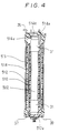
- Fig. 14 illustrates the secondary spool before it is assembled.
- a lead 512a extends from the secondary coil 512 between two longitudinal guides 510g formed on an outer periphery of the labyrinth member 510f as illustrated in Fig. 14. The lead 512a is connected to a terminal 20 of the primary coil 516.
- the upper support member 514a has openings 514d and 514g, and the labyrinth member 514f extends downward from the upper support member 514a to face the other labyrinth member 510f which extends upward from the upper open end of the secondary spool 510.
- Outside diameter of the labyrinth 514f is formed slightly smaller than inside diameter of the labyrinth 510f so that the insulating oil 29 infiltrate between them by capillarity. That is, the labyrinth members 510f and 514f are interposed between the lead 512a and the iron core 502 (and the magnet 504) so that the dielectric strength between them is increased.
- the primary spool 514 before it is assembled is shown in Fig. 15, in which the terminal 20 which is held on the upper support member 514a is also shown.
- Fig. 16 illustrates the primary spool 514 and the secondary spool 510 after they are assembled.
- the opening 514g of the primary spool's support member 514 is located above the longitudinal guides 510g of the secondary spool's labyrinth member 510f as shown in Fig. 16 so that the lead 512a passes through the opening 514g and connects with the terminal 20.
- Fig. 17 illustrates an upper portion of an ignition coil without the labyrinth members 510f and 514f when it is mounted on an engine with an inclination. Since the magnet member 504 is disposed near the secondary coil, a high tension voltage is induced thereon and voltage difference as high as 10 kV is generated between the magnet 504 and the lead 512. If the magnet 504 and the lead 512 are exposed to a space C above the level 29a of the insulating oil 29, the dielectric strength between them decreases and the high tension voltage may leak out through the lead 512a, thereby causing engine troubles.
- the labyrinth members 510f and 514f according to the seventh embodiment prevent the high tension voltage from leaking because they increase the creepage distance between the magnet 504 and the leads 512a significantly and the insulating oil 29 is retained between the labyrinth members 510f and 514f by capillarity.
- the labyrinth members 510f and 514f are also effective to assemble the primary spool 514 and the secondary spool 510 in place.
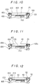
- FIG. 18 An eighth embodiment is illustrated in Fig. 18.
- the labyrinth members 510f and 514f of the seventh embodiment are replaced by a wall member 710f which extends longitudinally from the secondary spool 510.
- the lead 512a is disposed on an outer periphery of the wall member 710f at a side opposite the magnet 504.
- the wall member is interposed between the magnet 504 and the lead 512a.
- the labyrinth member 510f of the seventh embodiment is replaced with a cylindrical member 810f which has a thicker cylindrical wall and the labyrinth member 514f of the seventh embodiment is omitted. Therefore, the thicker wall is interposed between the lead 512a and the permanent magnet 504 and the creepage distance increases significantly.
- any other insulating member instead of the cylindrical member 810f can be used if it increases the creepage distance between the permanent magnet 504 and the lead 512a.
- a cylindrical member may be formed on the primary spool 514 instead of the member 810f.
- the ignition coil according to this embodiment is a variation of that of the seventh embodiment.
- Labyrinth members 510f, 514f and 510h are formed on the upper portion of the primary and secondary spools 514 and 510.
- the labyrinth member 514f which extends from the primary spool 514 is disposed between the labyrinth members 510f and 510h which extend upward from the secondary spool 510. Therefore, the creepage distance between the lead 512a and the permanent magnet 504 is increased and the dielectric strength is increased more.
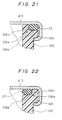
- Fig. 21 illustrates a sealing portion including a cover of an ignition coiil according to a eleventh embodiment.
- An outer annular groove 108b is formed at a peripheral surface of the open end of the case 100 when the case 100 is molded, and a rubber O-ring 25 is disposed thereon.
- a cover 410 made of stainless steel is fitted to the open end of the case 100 and presses the O-ring 25 against open end of the case.
- An open end of the cover 410 is bent and wrap a jaw portion 109 formed under the open end of the case 100.
- Inner diameter of the O-ring 25 before it is put in the groove is smaller than outer diameter of an annular wall 108c of the open end of the case 100 so that the O-ring 25 grips the wall tightly to have high sealing effect.
- the stainless cover 410 absorbs pressure change in the case 100. Since the O-ring 25 is disposed in the annular groove 108b formed on the open end of the case 100, outer diameter of the case can be reduced.
- An inner annular groove 108e is formed at an inner peripheral surface of the open end of the case 100 when the case 100 is molded. Outer diameter of the O-ring 25 before it is put in the groove is greater than outer diameter of an annular wall 108f of the open end of the case 100 so that the O-ring 25 presses the wall to have high sealing effect.
- Fig. 22 illustrates a sealing portion including a cover of an ignition coiil according to a twelfth embodiment.
- the stainless cover 410 absorbs pressure change in the case 100 and the outer diameter of the case 100 can be reduced for the same reasons as stated above.
- An ignition coil (1) has a cylindrical case (100) for directly mounting on a spark plug.
- the case 100 accommodates a transformer unit (5) which includes a primary coil (516) wound around a primary spool(514), a secondary coil (512) wounded around a secondary spool (510) and a plurality of magnetic circuit members (502, 504, 506) therein hermetically.
- the primary spool and the secondary spool have supporting members (514a, 510a) respectively. When they are assembled, the magnetic circuit members are retained between the spools automatically.
- the spools have insulating members (514f, 510f) interposed between the magnetic circuit members and a lead of the primary coil at an upper portion of the coil to increase the creepage distance between members connected respectively to the secondary coil and the primary coil.
Landscapes
- Engineering & Computer Science (AREA)
- Power Engineering (AREA)
- Ignition Installations For Internal Combustion Engines (AREA)
Applications Claiming Priority (6)
| Application Number | Priority Date | Filing Date | Title |
|---|---|---|---|
| JP229378/94 | 1994-09-26 | ||
| JP6229379A JPH0893616A (ja) | 1994-09-26 | 1994-09-26 | 点火コイル |
| JP6229378A JPH0897057A (ja) | 1994-09-26 | 1994-09-26 | 点火コイル |
| JP229379/94 | 1994-09-26 | ||
| JP11901/95 | 1995-01-27 | ||
| JP7011901A JPH08203757A (ja) | 1995-01-27 | 1995-01-27 | 内燃機関用点火コイル |
Publications (1)
| Publication Number | Publication Date |
|---|---|
| EP0703588A1 true EP0703588A1 (fr) | 1996-03-27 |
Family
ID=27279632
Family Applications (1)
| Application Number | Title | Priority Date | Filing Date |
|---|---|---|---|
| EP95115090A Withdrawn EP0703588A1 (fr) | 1994-09-26 | 1995-09-25 | Bobine d'allumage |
Country Status (2)
| Country | Link |
|---|---|
| EP (1) | EP0703588A1 (fr) |
| KR (1) | KR960012053A (fr) |
Cited By (9)
| Publication number | Priority date | Publication date | Assignee | Title |
|---|---|---|---|---|
| EP0837481A2 (fr) * | 1996-10-18 | 1998-04-22 | Denso Corporation | Bobine d'allumage pour moteur à combustion interne |
| EP0848394A1 (fr) * | 1996-12-10 | 1998-06-17 | General Motors Corporation | Bobine d'allumage et bougie d'allumage intégrées |
| US6213109B1 (en) | 1997-07-04 | 2001-04-10 | Hitachi, Ltd. | Ignition coil for use in internal combustion engine |
| ES2155365A1 (es) * | 1997-12-25 | 2001-05-01 | Denso Corp | Bobina de encendido con configuracion de posicionamiento en abertura para terminal del lado de la torre. |
| DE19829845C2 (de) * | 1997-07-04 | 2002-07-18 | Hitachi Ltd | Zündspule für Verbrennungsmotoren |
| EP1426985A2 (fr) * | 1997-02-14 | 2004-06-09 | Denso Corporation | Bobine d'allumage du type à tige présentant une structure améliorée pour éviter les fissures ou les décharges diélectriques |
| US6836203B2 (en) * | 2001-11-26 | 2004-12-28 | Denso Corporation | Ignition coil for internal combustion engine |
| US6930583B2 (en) | 1997-02-14 | 2005-08-16 | Denso Corporation | Stick-type ignition coil having improved structure against crack or dielectric discharge |
| US7471002B2 (en) | 2005-12-26 | 2008-12-30 | Denso Corporation | Voltage controller of alternator for vehicle |
Citations (8)
| Publication number | Priority date | Publication date | Assignee | Title |
|---|---|---|---|---|
| US1977122A (en) * | 1931-03-30 | 1934-10-16 | Electric Auto Lite Co | High tension apparatus |
| EP0020009A1 (fr) * | 1979-05-25 | 1980-12-10 | LUCAS INDUSTRIES public limited company | Bobine d'allumage avec dispositif de détente sensible à une pression excessive |
| EP0048632A1 (fr) * | 1980-09-24 | 1982-03-31 | Nippondenso Co., Ltd. | Bobines d'allumage pour moteur à combustion interne |
| DE3404064A1 (de) * | 1983-04-27 | 1984-11-08 | Aisin Seiki K.K., Kariya, Aichi | Zuendtransformator- und zuendkerzenabdeckungs-einheit |
| WO1985000930A1 (fr) * | 1983-08-05 | 1985-02-28 | Saab-Scania Aktiebolag | Unite d'allumage du systeme d'allumage d'un moteur a combustion interne |
| US4714909A (en) * | 1985-05-29 | 1987-12-22 | Hewlett-Packard Company | Support for transformer windings |
| EP0431322A1 (fr) * | 1989-11-10 | 1991-06-12 | Nippondenso Co., Ltd. | Bobine d'allumage |
| DE4132851A1 (de) * | 1990-10-03 | 1992-04-16 | Mitsubishi Electric Corp | Zuendspuleneinheit fuer eine verbrennungskraftmaschine |
-
1995
- 1995-09-25 EP EP95115090A patent/EP0703588A1/fr not_active Withdrawn
- 1995-09-26 KR KR1019950031885A patent/KR960012053A/ko not_active Application Discontinuation
Patent Citations (11)
| Publication number | Priority date | Publication date | Assignee | Title |
|---|---|---|---|---|
| US1977122A (en) * | 1931-03-30 | 1934-10-16 | Electric Auto Lite Co | High tension apparatus |
| EP0020009A1 (fr) * | 1979-05-25 | 1980-12-10 | LUCAS INDUSTRIES public limited company | Bobine d'allumage avec dispositif de détente sensible à une pression excessive |
| EP0048632A1 (fr) * | 1980-09-24 | 1982-03-31 | Nippondenso Co., Ltd. | Bobines d'allumage pour moteur à combustion interne |
| DE3404064A1 (de) * | 1983-04-27 | 1984-11-08 | Aisin Seiki K.K., Kariya, Aichi | Zuendtransformator- und zuendkerzenabdeckungs-einheit |
| WO1985000930A1 (fr) * | 1983-08-05 | 1985-02-28 | Saab-Scania Aktiebolag | Unite d'allumage du systeme d'allumage d'un moteur a combustion interne |
| JPS60501961A (ja) | 1983-08-05 | 1985-11-14 | サ−ブ−スカニア アクチボラグ | 内燃機関点火装置の点火器 |
| US4617907A (en) | 1983-08-05 | 1986-10-21 | Saab-Scania Aktiebolag | Ignition unit in the ignition system of an internal combustion engine |
| US4714909A (en) * | 1985-05-29 | 1987-12-22 | Hewlett-Packard Company | Support for transformer windings |
| EP0431322A1 (fr) * | 1989-11-10 | 1991-06-12 | Nippondenso Co., Ltd. | Bobine d'allumage |
| US5101803A (en) | 1989-11-10 | 1992-04-07 | Nippondenso Co., Ltd. | Ignition coil |
| DE4132851A1 (de) * | 1990-10-03 | 1992-04-16 | Mitsubishi Electric Corp | Zuendspuleneinheit fuer eine verbrennungskraftmaschine |
Cited By (19)
| Publication number | Priority date | Publication date | Assignee | Title |
|---|---|---|---|---|
| EP1304708A1 (fr) * | 1996-10-18 | 2003-04-23 | Denso Corporation | Bobine d'allumage pour moteur à combustion interne |
| EP0837481A3 (fr) * | 1996-10-18 | 1999-01-13 | Denso Corporation | Bobine d'allumage pour moteur à combustion interne |
| EP1655748A3 (fr) * | 1996-10-18 | 2006-08-23 | Denso Corporation | Bobine d'allumage pour moteur à combustion interne |
| EP1655748A2 (fr) * | 1996-10-18 | 2006-05-10 | Denso Corporation | Bobine d'allumage pour moteur à combustion interne |
| EP0837481A2 (fr) * | 1996-10-18 | 1998-04-22 | Denso Corporation | Bobine d'allumage pour moteur à combustion interne |
| US6747540B1 (en) | 1996-10-18 | 2004-06-08 | Denso Corporation | Ignition coil for internal combustion engine |
| EP0848394A1 (fr) * | 1996-12-10 | 1998-06-17 | General Motors Corporation | Bobine d'allumage et bougie d'allumage intégrées |
| US6930583B2 (en) | 1997-02-14 | 2005-08-16 | Denso Corporation | Stick-type ignition coil having improved structure against crack or dielectric discharge |
| EP1426985A2 (fr) * | 1997-02-14 | 2004-06-09 | Denso Corporation | Bobine d'allumage du type à tige présentant une structure améliorée pour éviter les fissures ou les décharges diélectriques |
| EP1426985A3 (fr) * | 1997-02-14 | 2004-06-23 | Denso Corporation | Bobine d'allumage du type à tige présentant une structure améliorée pour éviter les fissures ou les décharges diélectriques |
| US6995644B2 (en) | 1997-02-14 | 2006-02-07 | Denso Corporation | Stick-type ignition coil having improved structure against crack or dielectric discharge |
| US7068135B1 (en) | 1997-02-14 | 2006-06-27 | Denso Corporation | Stick-type ignition coil having improved structure against crack or dielectric discharge |
| US7071804B2 (en) | 1997-02-14 | 2006-07-04 | Denso Corporation | Stick-type ignition coil having improved structure against crack or dielectric discharge |
| DE19829845C2 (de) * | 1997-07-04 | 2002-07-18 | Hitachi Ltd | Zündspule für Verbrennungsmotoren |
| US6237578B1 (en) | 1997-07-04 | 2001-05-29 | Hitachi, Ltd. | Ignition coil for use in internal combustion engine |
| US6213109B1 (en) | 1997-07-04 | 2001-04-10 | Hitachi, Ltd. | Ignition coil for use in internal combustion engine |
| ES2155365A1 (es) * | 1997-12-25 | 2001-05-01 | Denso Corp | Bobina de encendido con configuracion de posicionamiento en abertura para terminal del lado de la torre. |
| US6836203B2 (en) * | 2001-11-26 | 2004-12-28 | Denso Corporation | Ignition coil for internal combustion engine |
| US7471002B2 (en) | 2005-12-26 | 2008-12-30 | Denso Corporation | Voltage controller of alternator for vehicle |
Also Published As
| Publication number | Publication date |
|---|---|
| KR960012053A (ko) | 1996-04-20 |
Similar Documents
| Publication | Publication Date | Title |
|---|---|---|
| EP1253606B1 (fr) | Bobine d'allumage du type à tige présentant une structure améliorée pour éviter les fissures ou les décharges diélectriques | |
| US5349320A (en) | Ignition coil for internal combustion engines | |
| US6154113A (en) | Transformer and method of assembling same | |
| JP3727764B2 (ja) | エンジン用点火コイル装置及びその製造方法 | |
| US7710231B2 (en) | Ignition coil | |
| EP0703588A1 (fr) | Bobine d'allumage | |
| EP0826879B1 (fr) | Dispositif d'allumage constitué de bobine et de circuit d'allumage pour un moteur à combustion interne | |
| US20020158740A1 (en) | Ignition apparatus having reduced electric field HV terminal arrangement | |
| EP0048632B1 (fr) | Bobines d'allumage pour moteur à combustion interne | |
| US6747540B1 (en) | Ignition coil for internal combustion engine | |
| EP0843394B1 (fr) | Dispositif d'allumage pour moteur à combustion interne | |
| US6836203B2 (en) | Ignition coil for internal combustion engine | |
| US5758624A (en) | Ignition coil and method of manufacturing the same | |
| US7626481B2 (en) | Ignition coil | |
| US6559747B2 (en) | Ignition coil | |
| EP0609850B1 (fr) | Ensemble de transformateur et boítier de bobine | |
| JPH0897057A (ja) | 点火コイル | |
| US2131483A (en) | Ignition coil | |
| JPH0893616A (ja) | 点火コイル | |
| KR100689174B1 (ko) | 스틱형 점화 코일 및 이의 단자 조립체 | |
| JPH08144916A (ja) | 内燃機関のプラグチューブおよび点火装置 | |
| JP3629983B2 (ja) | 点火コイル | |
| JP3783957B2 (ja) | 内燃機関用点火コイル | |
| JP3828596B2 (ja) | 内燃機関用点火装置 | |
| JPH09246074A (ja) | 内燃機関用点火コイル |
Legal Events
| Date | Code | Title | Description |
|---|---|---|---|
| PUAI | Public reference made under article 153(3) epc to a published international application that has entered the european phase |
Free format text: ORIGINAL CODE: 0009012 |
|
| AK | Designated contracting states |
Kind code of ref document: A1 Designated state(s): DE FR GB IT |
|
| 17P | Request for examination filed |
Effective date: 19960328 |
|
| 17Q | First examination report despatched |
Effective date: 19960621 |
|
| RAP1 | Party data changed (applicant data changed or rights of an application transferred) |
Owner name: DENSO CORPORATION |
|
| STAA | Information on the status of an ep patent application or granted ep patent |
Free format text: STATUS: THE APPLICATION IS DEEMED TO BE WITHDRAWN |
|
| 18D | Application deemed to be withdrawn |
Effective date: 19980401 |