EP0703397B1 - Raccord de fixation pour un tube annelé - Google Patents
Raccord de fixation pour un tube annelé Download PDFInfo
- Publication number
- EP0703397B1 EP0703397B1 EP95202554A EP95202554A EP0703397B1 EP 0703397 B1 EP0703397 B1 EP 0703397B1 EP 95202554 A EP95202554 A EP 95202554A EP 95202554 A EP95202554 A EP 95202554A EP 0703397 B1 EP0703397 B1 EP 0703397B1
- Authority
- EP
- European Patent Office
- Prior art keywords
- sleeve
- tube
- ring
- ringed
- fastening
- Prior art date
- Legal status (The legal status is an assumption and is not a legal conclusion. Google has not performed a legal analysis and makes no representation as to the accuracy of the status listed.)
- Expired - Lifetime
Links
- 230000008878 coupling Effects 0.000 title claims abstract description 61
- 238000010168 coupling process Methods 0.000 title claims abstract description 61
- 238000005859 coupling reaction Methods 0.000 title claims abstract description 61
- 230000003014 reinforcing effect Effects 0.000 claims description 4
- 239000012530 fluid Substances 0.000 description 9
- 238000007789 sealing Methods 0.000 description 7
- 230000037431 insertion Effects 0.000 description 5
- 238000003780 insertion Methods 0.000 description 5
- 239000000463 material Substances 0.000 description 5
- 206010022000 influenza Diseases 0.000 description 4
- KRHYYFGTRYWZRS-UHFFFAOYSA-M Fluoride anion Chemical compound [F-] KRHYYFGTRYWZRS-UHFFFAOYSA-M 0.000 description 3
- 238000010438 heat treatment Methods 0.000 description 3
- 239000002184 metal Substances 0.000 description 3
- 229920006373 Solef Polymers 0.000 description 2
- 229920001971 elastomer Polymers 0.000 description 2
- 239000000806 elastomer Substances 0.000 description 2
- 238000000926 separation method Methods 0.000 description 2
- 241000826860 Trapezium Species 0.000 description 1
- 230000032683 aging Effects 0.000 description 1
- 238000005452 bending Methods 0.000 description 1
- 230000009286 beneficial effect Effects 0.000 description 1
- 239000000567 combustion gas Substances 0.000 description 1
- 230000007797 corrosion Effects 0.000 description 1
- 238000005260 corrosion Methods 0.000 description 1
- 230000000694 effects Effects 0.000 description 1
- 238000007689 inspection Methods 0.000 description 1
- 230000035515 penetration Effects 0.000 description 1
- 230000000750 progressive effect Effects 0.000 description 1
- 239000004071 soot Substances 0.000 description 1
- 238000010408 sweeping Methods 0.000 description 1
- 231100000331 toxic Toxicity 0.000 description 1
- 230000002588 toxic effect Effects 0.000 description 1
Images


Classifications
-
- F—MECHANICAL ENGINEERING; LIGHTING; HEATING; WEAPONS; BLASTING
- F16—ENGINEERING ELEMENTS AND UNITS; GENERAL MEASURES FOR PRODUCING AND MAINTAINING EFFECTIVE FUNCTIONING OF MACHINES OR INSTALLATIONS; THERMAL INSULATION IN GENERAL
- F16L—PIPES; JOINTS OR FITTINGS FOR PIPES; SUPPORTS FOR PIPES, CABLES OR PROTECTIVE TUBING; MEANS FOR THERMAL INSULATION IN GENERAL
- F16L25/00—Constructive types of pipe joints not provided for in groups F16L13/00 - F16L23/00 ; Details of pipe joints not otherwise provided for, e.g. electrically conducting or insulating means
- F16L25/0036—Joints for corrugated pipes
- F16L25/0045—Joints for corrugated pipes of the quick-acting type
-
- F—MECHANICAL ENGINEERING; LIGHTING; HEATING; WEAPONS; BLASTING
- F16—ENGINEERING ELEMENTS AND UNITS; GENERAL MEASURES FOR PRODUCING AND MAINTAINING EFFECTIVE FUNCTIONING OF MACHINES OR INSTALLATIONS; THERMAL INSULATION IN GENERAL
- F16L—PIPES; JOINTS OR FITTINGS FOR PIPES; SUPPORTS FOR PIPES, CABLES OR PROTECTIVE TUBING; MEANS FOR THERMAL INSULATION IN GENERAL
- F16L37/00—Couplings of the quick-acting type
- F16L37/08—Couplings of the quick-acting type in which the connection between abutting or axially overlapping ends is maintained by locking members
- F16L37/12—Couplings of the quick-acting type in which the connection between abutting or axially overlapping ends is maintained by locking members using hooks, pawls or other movable or insertable locking members
-
- Y—GENERAL TAGGING OF NEW TECHNOLOGICAL DEVELOPMENTS; GENERAL TAGGING OF CROSS-SECTIONAL TECHNOLOGIES SPANNING OVER SEVERAL SECTIONS OF THE IPC; TECHNICAL SUBJECTS COVERED BY FORMER USPC CROSS-REFERENCE ART COLLECTIONS [XRACs] AND DIGESTS
- Y10—TECHNICAL SUBJECTS COVERED BY FORMER USPC
- Y10S—TECHNICAL SUBJECTS COVERED BY FORMER USPC CROSS-REFERENCE ART COLLECTIONS [XRACs] AND DIGESTS
- Y10S285/00—Pipe joints or couplings
- Y10S285/903—Corrugated
Definitions
- the subject of the present invention is a fastening coupling for a ringed tube according to the preamble of claim 1.
- French Patent FR 2,391,411 proposes a coupling for two tubes, at least one of which is a corrugated tube including helical ribs.
- This coupling comprises an annular coupling element engaged in a groove of the corrugations of a first tube close to its end, so that it projects radially around the tube, and an annular stop mounted on the second tube.
- the annular coupling element is fastened to the stop so as to hold the two tubular elements together.
- this type of coupling has to be tightened a great deal, and any relative rotational movement of one tube with respect to the other would break the seal of the coupling.
- Described in European Patent EP 0,444,857 B1 is a coupling making it possible to join a corrugated tube to a coupling member in a sealed manner and without a screw thread.
- This member comprises a cylindrical cavity in which one end of the corrugated tube is housed.
- a split ring which can expand radially is fastened to the end of the corrugated tube.
- the split ring is compressed and locks into a circumferential groove made in the cylindrical cavity. Sealing is provided by one or more toric seals mounted on the corrugated tube behind the split ring.
- One of the main disadvantages of this type of coupling is that it is almost impossible to take apart without destroying it.
- the object of the present invention is to propose a non-threaded fastening coupling for a ringed tube which can easily be fitted and taken apart, and which withstands possible tension and rotation exerted on the tube. It is especially desirable for it to be possible for this coupling easily to be sealed against the fluids conveyed.
- This type of coupling finds a particularly advantageous application in the lining of flues for domestic heating, with a view to shielding the walls of chimneys from the aggressive action of the combustion gases and corrosive condensates.
- each orifice comprises a wide part and a narrow part, these parts being adjacent and intercommunicating, and each tenon passing through the wide part of an orifice, it being possible, by rotating the ring, to fit the narrow base of each tenon into the narrow part of an orifice so as to prevent any radial movement of the ring.
- a ringed tube is intended to denote a tube, the wall of which comprises numerous channels and protrusions on its outside surface.
- such tubes are cylindrical overall, and their channels and protrusions have symmetry of revolution.
- the present invention is also applicable to ringed tubes whose cross section may be other than circular, for example elliptical.
- Such tubes may especially consist of metal or plastic. When they are intended for lining flues, these tubes are often made of polyvinylidine fluoride.
- polyvinylidine fluoride By way of example of such lining tubes, mention may be made of the RENOFLEX® tubes by the company DRAKA POLVA, made from polyvinylidine fluoride SOLEF® (by the company SOLVAY).
- Fastening coupling is intended to denote any device making it possible to couple, in a straight or otherwise fashion, one tube to another tube or to any appliance such as a pump, a boiler, or alternatively to a blanking piece, without any risk of the tube detaching from the coupling under the effect of vibration or tensile or rotational forces.
- Sleeve denotes a hollow body open at least at one of its ends, and often at both ends.
- the sleeves used in the context of the invention have the overall shape of a cylinder, or consist of several successive cylindrical sections of different diameters.
- the sleeve may be made of any material suitable for this use and for the fluids conveyed, as explained hereinabove for the tubes.
- the orifices made in the sleeve are preferably uniformly spaced around it; thus, for example, they are preferably diametrally opposed when they are two in number.
- the ring may be made of any appropriate material, for example metal or plastic, provided that the two ends can be separated radially in order to fit it around the sleeve.
- the width of the slot separating the two ends of the ring is selected as a function of the outside diameter of the sleeve and of the flexibility of the ring.
- the outside surface of the ring has one or more transverse and/or circumferential ribs, in order to increase its rigidity.
- the tenons with which the ring is provided are generally circumferentially elongate and preferably have a substantially rectangular developed section, as do the wide parts of the orifices made in the sleeve, through which they have to be able to pass.
- these tenons have dimensions very slightly smaller than those of the wide parts of the orifices.
- the base of a tenon may either form a narrow region continuously connected to the end of the tenon by progressive widening, or constitute a region of small but constant width preceding the end of the tenon which has a greater width.
- the tenons are intended to engage in the ringed structure of the tube; for preference, the shape of the ends of the tenons corresponds to that of the channels exhibited by the outside wall of the tube, so that the ends of the tenons can be accommodated in these channels and firmly immobilize the tube in the axial direction, while not totally preventing any possible rotation.
- the ends of the tenons, in transverse section preferably have an appropriate section, for example in the shape of a trapezium, with the corners possibly rounded off.
- the length, width, and number of the tenons are especially chosen as a function of the diameter of the sleeve and of the tensile force that the coupling is to withstand. If this force is high, tenons will be chosen whose lateral surface for bearing against the ringed tube is relatively greater than for a coupling which is subjected merely to small forces.
- One advantage of the coupling according to the present invention lies in the fact that it can be fitted easily, without special tooling. Furthermore, it can be disassembled and reassembled several times over without the quality of the coupling suffering as a result. In addition, after coupling, the ringed tube can still undergo rotation about its axis without this detracting from the quality of the coupling.
- the coupling of the present invention may be sealed by means of at least one seal located close to the end of the tube, between the outside surface thereof and the sleeve, so as to improve the sealing of the coupling against fluids.
- This seal may be made from any material known for this purpose; this is generally an elastomer suited to the envisaged use.
- a fluorinated elastomer may especially be used.
- the section, the number of seals and their quality depend on the degree of sealing which is desired to be obtained, as well as on the nature and properties of the fluid transported in the tube. It is important to emphasize that the sealing function is independent of the coupling function.
- the section of the seal may be arbitrary, for example toric or trapezoidal.
- the section of the seal corresponds to the shape of the channels in the outside wall of the tube, so that it can be inserted between two channels and be axially immobilized there.
- the seal may include, on its outside face, that is to say, the one that will be in contact with the inside surface of the sleeve, one or more annular lips so as to reduce friction during the insertion of that end of the tube which is equipped with the seal inside the sleeve, while guaranteeing a high degree of sealing.
- the position of the seal on the end of the tube is chosen so that the seal finds itself inside the sleeve once the end of the tube has been inserted therein, and thus provides sealing between the tube and the sleeve. More precisely, it is appropriate for the seal to be arranged at a location situated between the end of the tube and the orifices into which the ends of the tenons will be inserted once the fastening ring has been installed, in order to prevent any leakage through these orifices.
- the outside surface of the sleeve includes a stop preventing the fastening ring from turning after it has been installed.
- the position of the stop is generally chosen to be in immediate proximity to one of the two ends of the ring when the latter is in its final position. In this way, the ring can no longer turn in either direction. In point of fact, in one direction the rotation is limited by the narrow parts of the orifices, and in the other by the stop. The fastening therefore cannot become undone unintentionally even if it subjected to vibration or rotation of the tube.
- the outside surface of the sleeve is equipped with a seat delimited by protrusions, so as to facilitate the axial positioning of the ring.
- protrusions may for example consist of small pads uniformly spaced around the periphery of the sleeve, and aligned circumferentially, so as to form two circular rows the separation of which corresponds to the width of the ring. They may equally well consist of two continuous or discontinuous ribs with the same separation. These protrusions facilitate the positioning of the fastening ring on the sleeve and may contribute to reinforcing the latter. To this end, the use of two continuous ribs is preferred.
- the space inside the sleeve comprises an annular shoulder forming an internal stop against which the end of the ringed tube rests.
- this annular stop is situated after the orifices through which the tenons of the ring can pass. This stop prevents the ringed tube from being inserted too far into the sleeve.
- the inside edge of the annular shoulder has a projection coaxial with the sleeve and forming with the inside surface of the sleeve an annular region in which the end of the ringed tube is housed.
- the projection may be continuous or discontinuous; in the latter case, it is preferable for the projection to be present at least in line with the narrow parts of the orifices of the sleeve.
- the annular shoulder is equipped with a section of cylinder coaxial with the sleeve, the diameter of which corresponds to the inside diameter of the annular shoulder.
- This projection of the inside edge of the annular shoulder makes it possible to strengthen the tube against radial compressive loads that may in some cases be brought about by the tenons with which the fastening ring is provided and/or the seal(s). Furthermore, the annular shoulder and its projection or projections may contribute to facilitating the flow of fluid inside the coupling close to the end of the tube.
- the coupling further comprises a reinforcing piece which is inserted inside the end of the ringed tube.
- This piece reinforces the tube inside the sleeve and strengthens it against the radial compressive load that may in some cases be brought about by the tenons with which the fastening ring is equipped and/or the seal(s). Furthermore, if its length is sufficient, this piece reinforces the tube at the sleeve entrance. In this way, the risk of the edge of the sleeve damaging the tube, for example in the event of the tube bending, is minimized.
- the piece preferably includes at one of its ends a continuous or discontinuous outwardly pointing annular rim, the outside diameter of which is such that it still allows the piece to be inserted into the sleeve, in order to guarantee that this piece remains located at the end of the tube and does not move axially inside it.
- the piece may be made of any material suitable for this use and for the fluids conveyed, for example metal or plastic. Its section is matched to that of the inside of the tube; and it is generally circular.
- end of the sleeve pointing towards the ringed tube has a frustoconical part, especially so as to facilitate the insertion of the tube into it.
- the frustoconical part is particularly useful for connecting a tube of relatively large diameter to a coupling. Indeed, as the inside diameter of the sleeve has a diameter substantially equal to the largest outside diameter of the ringed tube, the frustoconical part situated at the sleeve entrance will facilitate the insertion of the tube. Furthermore, this frustoconical part avoids the seal located at the end of the tube being moved or damaged while the end of the tube is being inserted into the sleeve.
- the coupling may advantageously include a channel for guiding the tenons.
- This channel may be continuous or exist only near to the orifices. It allows the tenons to be guided into the orifices, while the fastening ring is being installed around the sleeve, something which may be useful when performing a coupling operation at a site which is not readily accessible, when an operator is coupling a tube without being able to see it.
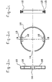
- the fastening ring is identified overall by the reference 10. It comprises two tenons 12 projecting inwards, and diametrically opposed.
- a slot 14 is made in the ring 10 so that its two ends can be separated radially in order to fit it around the sleeve.
- the width of the slot 14 of the ring 10 is chosen as a function of the outside diameter of the sleeve and of the flexibility of the ring. It goes without saying that this ring has to be made of a sufficiently flexible material so that it can be expanded radially in order to fit around the sleeve (see Figure 3).
- FIGS 2a, 2b and 2c represent various views of the sleeve 18 of a coupling in accordance with the invention.
- the seat 20 on which the fastening ring (not represented) may be located This seat is delimited on each side by a rib 22 which serves as a guide when the fastening ring is being applied.
- a guide channel 24 Provided at the centre of this seat is a guide channel 24, into which the tenons 12 of the fastening ring 10 can slide while it is being applied.
- the outside surface of the sleeve also comprises a stop 26.
- the orifices 28 comprise a wide part 30 and an adjacent narrower part 32.
- the wide part 30 of the orifices 28 is dimensioned so that the tenons 12 of the ring 10 can easily penetrate them while the narrow part 32 of the orifices 28 is dimensioned as a function of the bases of the tenons, which are narrower, so that these can engage therein, thus preventing the fastening ring 10 from being expanded radially after it has been installed.
- the space 34 inside the sleeve, where the ringed tube (not represented) will become housed, comprises an annular shoulder 36 forming a stop for the ringed tube.
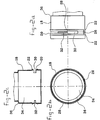
- Figures 3a, 4a, 3b, 4b and 3c, 4c show a sequence in the fitting together of the coupling according to the present invention.
- the tenons 12 penetrate the wide parts 30 of the orifices 28, the dimensions of which have been selected for this purpose. As the tenons 12 are wider than the narrow parts 32 of the orifices 28 but less wide than their wide parts 30, they can engage directly only in the latter parts. As the fastening ring 10 is under tension as it has been expanded radially, the tenons 12 will be pushed into the wide parts 30 of the orifices 28 as soon as they come to face them, as represented in Figures 3b and 4b.
- the fastening ring 10 By continuing to turn the fastening ring 10 in the same direction, the narrow bases 13 of the tenons 12 engage in the narrow parts 32 of the orifices 28.
- the fastening ring 10, in this position, can no longer be expanded radially.
- the ends of the tenons 12 are engaged between 2 ribs of the ringed tube, the end of which had previously been inserted inside 34 the sleeve, so as to retain the tube axially.
- the stop 26 prevents the fastening ring 10 from turning in the opposite direction, i.e. it is not possible for the fastening ring 10 to return to its initial position without its end in contact with the stop 26 being lifted somewhat.
- the position of the stop 26 is preferably chosen so that it is in immediate proximity to or in contact with an end of the fastening ring 10 when the latter is in its final position.
- FIG. 5 shows a T-piece 38 which comprises two couplings 40 and 42 in accordance with the invention and an inspection opening or opening for the coupling of a side line 44, blanked off by a screwed-on cover 46.
- This device is designed to be used for lining flues for domestic heating. It connects together two ringed RENOFLEX® tubes from the company DRAKA POLVA, made from polyvinylidine fluoride SOLEF® (from the company SOLVAY). These tubes display excellent resistance to corrosion and to aging, even in very severe conditions. The external appearance of these tubes is quite specific in that the corrugations are not uniform but are in the form of separate groups of several ribs and channels, separated by purely cylindrical sections. The coupling element of Figure 5 is particularly useful for coupling this sort of tube.
- the couplings 40 and 42 are of the same type as the one represented in the preceding figures. After assembly, the ends of the tenons 12 are located between two groups of ribs and channels of the tube. In this way, the tube is axially immobilised inside the sleeve.
- the tubes 48 are equipped with a toric seal 50 of trapezoidal section, equipped with a lip 52 pointing outwards, preventing any leak of toxic or corrosive emanations.
- the space inside the coupling 40 includes an annular shoulder 36 forming a stop for the ringed tube.
- annular shoulder 36 On the inside edge of this annular shoulder is fastened a cylindrical projection 54 which, together with the inside wall of the sleeve, forms an annular region in which the end of the tube 48 is housed. This region serves as a guide for the tube and improves the flow of fluid inside the coupling.
- this annular shoulder 36 and this projection 54 also facilitate the sweeping of the chimney and prevent soot or condensates from being deposited between the coupling and the tube.
- the end of the tube was reinforced by an internal cylindrical piece 56, the end of which includes an outwardly pointing annular rim which limits its penetration into the tube.
Claims (9)
- Raccord de fixation pour un tube annelé, comprenant au moins un manchon (18) dont le diamètre intérieur est au moins égal au diamètre extérieur le plus grand du tube annelé, dans lequel une extrémité du tube annelé vient se loger de même qu'une bague (10) de fixation, ledit manchon (18) comprenant au moins deux orifices (28) alignés circonférentiellement, ladite bague (10) étant discontinue circonférentiellement et déformable radialement et étant pourvue d'au moins deux tenons (12) en saillie vers l'intérieur, chacun comprenant une base étroite (13), laquelle bague (10) peut être appliquée autour du manchon (18) de sorte que chaque tenon (12) traverse l'orifice (28) et rentre dans la structure annelée du tube (48) de façon à le maintenir axialement à l'intérieur du manchon (18), caractérisé en ce que chaque orifice (28) comprend une partie large (30) et une partie étroite (32), ces parties étant adjacentes et en communication mutuelle, et en ce que, chaque tenon (12) traversant la partie large (30) d'un orifice (28), il est possible, en faisant tourner la bague (10), d'introduire la base étroite (13) de chaque tenon dans la partie étroite (32) d'un orifice (28) de façon à empêcher tout déplacement radial de cette bague (10).
- Raccord de fixation selon la revendication 1, comprenant en outre au moins un joint (50) situé à proximité de l'extrémité du tube, entre sa surface extérieure et le manchon (18).
- Raccord de fixation selon l'une ou l'autre des revendications précédentes, dans lequel la surface extérieure du manchon (18) comprend une butée (26) empêchant la bague (10) de fixation de tourner après Installation.
- Raccord de fixation selon l'une quelconque des revendications précédentes, dans lequel la surface extérieure du manchon (18) est équipée d'une surface d'appui (20) délimitée par des saillies (22) de façon à faciliter le placement axial de la bague (10).
- Raccord de fixation selon l'une quelconque des revendications précédentes, dans lequel l'espace (34) à l'intérieur du manchon (18) comprend un épaulement annulaire (36) formant une butée interne contre laquelle l'extrémité du tube annelé peut s'appuyer.
- Raccord de fixation selon la revendication 5, dans lequel le bord intérieur de l'épaulement annulaire (36) comporte une saillie (54) coaxiale au manchon (18) et formant avec la surface Intérieure de ce manchon une région annulaire dans laquelle se loge l'extrémité du tube annelé.
- Raccord de fixation selon l'une quelconque des revendications précédentes, comprenant en outre un élément (56) de renfort que l'on introduit à l'intérieur de l'extrémité du tube annelé.
- Raccord de fixation selon l'une quelconque des revendications précédentes, dans lequel l'extrémité du manchon (18) dirigée vers le tube annelé comporte une partie tronconique.
- Raccord de fixation selon l'une quelconque des revendications précédentes comprenant, sur la surface extérieure du manchon, un canal (24) servant à guider les tenons (12).
Applications Claiming Priority (2)
| Application Number | Priority Date | Filing Date | Title |
|---|---|---|---|
| BE9400866A BE1008705A3 (fr) | 1994-09-23 | 1994-09-23 | Raccord de fixation pour un tube annele. |
| BE9400866 | 1994-09-23 |
Publications (2)
| Publication Number | Publication Date |
|---|---|
| EP0703397A1 EP0703397A1 (fr) | 1996-03-27 |
| EP0703397B1 true EP0703397B1 (fr) | 1999-09-01 |
Family
ID=3888376
Family Applications (1)
| Application Number | Title | Priority Date | Filing Date |
|---|---|---|---|
| EP95202554A Expired - Lifetime EP0703397B1 (fr) | 1994-09-23 | 1995-09-21 | Raccord de fixation pour un tube annelé |
Country Status (8)
| Country | Link |
|---|---|
| US (1) | US5632512A (fr) |
| EP (1) | EP0703397B1 (fr) |
| JP (1) | JPH08338577A (fr) |
| AT (1) | ATE184085T1 (fr) |
| BE (1) | BE1008705A3 (fr) |
| DE (1) | DE69511809T2 (fr) |
| ES (1) | ES2135657T3 (fr) |
| GR (1) | GR3031862T3 (fr) |
Families Citing this family (12)
| Publication number | Priority date | Publication date | Assignee | Title |
|---|---|---|---|---|
| EP1103752A1 (fr) * | 1999-11-26 | 2001-05-30 | Eureka Immobiliare S.r.l. | Tube ondulé flexible avec des raccords d'extremité pour systèmes hydrauliques |
| GB0202303D0 (en) * | 2002-02-01 | 2002-03-20 | Smiths Group Plc | Pipe couplings |
| US6929034B1 (en) * | 2002-06-20 | 2005-08-16 | Richard R. Larsen | Coupling system, kit, and method |
| EP1653141B1 (fr) * | 2004-10-29 | 2010-05-19 | ARGO-HYTOS GmbH | Dispositif de connection et dispositif de filtrage avec un tel dispositif de connection |
| SE529111C2 (sv) * | 2005-09-30 | 2007-05-02 | Itw Sverige Ab | Kopplingsanordning för sammankoppling av rörformade segment samt kopplingssystem innefattande kopplingsanordning |
| US20070252389A1 (en) * | 2006-04-27 | 2007-11-01 | Dywidag-Systems International | Duct Coupling Assembly |
| US9050430B2 (en) * | 2008-06-24 | 2015-06-09 | John Mathews | Auscultation interface |
| DE102010035027A1 (de) | 2010-08-20 | 2012-02-23 | Voss Automotive Gmbh | Verriegelungselement für einen Steckverbinder und Steckverbinder mit einem solchen Verriegelungselement |
| DE102014102794B4 (de) | 2014-03-03 | 2018-05-03 | Fsp Fluid Systems Partners Holding Ag | Filtervorrichtung zum Filtrieren einer Hydraulikflüssigkeit |
| US10024044B2 (en) * | 2014-09-12 | 2018-07-17 | Mark Fisher | Device and method for securing a drain tile |
| DE102014219076A1 (de) * | 2014-09-22 | 2016-03-24 | Fränkische Industrial Pipes GmbH & Co. KG | Verbindungsanordnung |
| DE102021112893A1 (de) | 2021-05-18 | 2022-11-24 | CENA-Kunststoff GmbH | Verbinder für ein Wellrohr |
Family Cites Families (15)
| Publication number | Priority date | Publication date | Assignee | Title |
|---|---|---|---|---|
| US2260712A (en) * | 1938-07-30 | 1941-10-28 | William H Harrison | Coupling device |
| US3352576A (en) * | 1965-08-24 | 1967-11-14 | Olin Mathieson | Tube coupling having split ring locking means |
| US3309113A (en) * | 1966-02-24 | 1967-03-14 | Hoover Co | Coupling for suction cleaner attachments |
| US3428340A (en) * | 1967-03-20 | 1969-02-18 | Harry L Pelton | Hose coupling |
| US3439943A (en) * | 1967-07-06 | 1969-04-22 | Olin Mathieson | Quick connect-disconnect coupling |
| GB1600746A (en) | 1977-05-17 | 1981-10-21 | Ti Flexible Tubes Ltd | Swaged joint |
| CH652471A5 (de) * | 1981-09-07 | 1985-11-15 | Alfred Grossauer | Anschlussnippel fuer umfangsgerippte isolierrohre. |
| AU9093182A (en) * | 1981-11-26 | 1983-06-02 | Sabco Ltd. | Quick release hose coupling |
| US4591192A (en) * | 1984-03-15 | 1986-05-27 | Rain Bird Consumer Products Mfg. Corp. | Quick connect coupling |
| JP2557399B2 (ja) * | 1987-04-28 | 1996-11-27 | 北川工業株式会社 | 波形管接続具 |
| DE3903355A1 (de) * | 1989-02-04 | 1990-08-09 | Hummel Metallwarenfab A | Anschlussarmatur fuer umfangsgerippte schlaeuche oder rohre |
| US4989905A (en) * | 1990-02-05 | 1991-02-05 | Lamson & Sessions Co. | Fitting for corrugated tubing |
| GB2241547A (en) * | 1990-02-28 | 1991-09-04 | Senior Tift Ltd | Snap action fluid tight coupling for corrugated tube |
| IL105065A (en) * | 1992-03-28 | 1995-05-26 | Smiths Ind Public Ltd | author |
| DE9312151U1 (de) * | 1992-08-17 | 1994-06-16 | Murrplastik Systemtechnik Gmbh | Schnellkupplung für Schläuche |
-
1994
- 1994-09-23 BE BE9400866A patent/BE1008705A3/fr not_active IP Right Cessation
-
1995
- 1995-09-21 DE DE69511809T patent/DE69511809T2/de not_active Expired - Lifetime
- 1995-09-21 EP EP95202554A patent/EP0703397B1/fr not_active Expired - Lifetime
- 1995-09-21 AT AT95202554T patent/ATE184085T1/de not_active IP Right Cessation
- 1995-09-21 JP JP7266139A patent/JPH08338577A/ja active Pending
- 1995-09-21 ES ES95202554T patent/ES2135657T3/es not_active Expired - Lifetime
- 1995-09-25 US US08/533,288 patent/US5632512A/en not_active Expired - Fee Related
-
1999
- 1999-11-17 GR GR990402956T patent/GR3031862T3/el unknown
Also Published As
| Publication number | Publication date |
|---|---|
| BE1008705A3 (fr) | 1996-07-02 |
| ES2135657T3 (es) | 1999-11-01 |
| US5632512A (en) | 1997-05-27 |
| DE69511809T2 (de) | 2000-03-16 |
| ATE184085T1 (de) | 1999-09-15 |
| JPH08338577A (ja) | 1996-12-24 |
| DE69511809D1 (de) | 1999-10-07 |
| EP0703397A1 (fr) | 1996-03-27 |
| GR3031862T3 (en) | 2000-02-29 |
Similar Documents
| Publication | Publication Date | Title |
|---|---|---|
| EP0702184B1 (fr) | Anneau de retenue | |
| EP0703397B1 (fr) | Raccord de fixation pour un tube annelé | |
| US4480860A (en) | Transition coupling and clamp assembly containing same | |
| AU767022B2 (en) | Quick connect/disconnect hose coupling | |
| KR940011855B1 (ko) | 파이프 커플링 | |
| US5048875A (en) | Connector interposed between small-diameter metallic pipe and flexible hose | |
| US6439617B1 (en) | Coupler for a pipe or hose section | |
| US5511830A (en) | Quick connect tube couplings | |
| KR940009569A (ko) | 파형의 가요성 관용 조인트 | |
| US5551732A (en) | Quick connector | |
| US5826920A (en) | Conduit coupling | |
| US5082313A (en) | Cut-in repair coupling | |
| US6170886B1 (en) | Quick connector | |
| JPH01320396A (ja) | カップリング | |
| US3853338A (en) | Coupling | |
| US4199157A (en) | Two part sleeve gasket | |
| KR100261327B1 (ko) | 방사방향으로 설치되는 유체 누설방지용 연결구 | |
| KR100633004B1 (ko) | 내열배관용 조인트 | |
| US4265471A (en) | Pipe joint | |
| US4108446A (en) | Pipe coupling socket assemblies | |
| JPH10132365A (ja) | 2本の金属パイプをシール状態で突き合せ接続するための接続装置 | |
| EP0542530B1 (fr) | Joint d'étanchéité | |
| KR20040045453A (ko) | 연결조립체 | |
| JPS5833437B2 (ja) | パイプの連結装置 | |
| EP0729556B1 (fr) | Systeme de couplage avec connecteur rapide |
Legal Events
| Date | Code | Title | Description |
|---|---|---|---|
| PUAI | Public reference made under article 153(3) epc to a published international application that has entered the european phase |
Free format text: ORIGINAL CODE: 0009012 |
|
| AK | Designated contracting states |
Kind code of ref document: A1 Designated state(s): AT BE DE ES FR GB GR IT NL PT SE |
|
| 17P | Request for examination filed |
Effective date: 19960913 |
|
| 17Q | First examination report despatched |
Effective date: 19981016 |
|
| GRAG | Despatch of communication of intention to grant |
Free format text: ORIGINAL CODE: EPIDOS AGRA |
|
| GRAG | Despatch of communication of intention to grant |
Free format text: ORIGINAL CODE: EPIDOS AGRA |
|
| GRAH | Despatch of communication of intention to grant a patent |
Free format text: ORIGINAL CODE: EPIDOS IGRA |
|
| GRAH | Despatch of communication of intention to grant a patent |
Free format text: ORIGINAL CODE: EPIDOS IGRA |
|
| GRAA | (expected) grant |
Free format text: ORIGINAL CODE: 0009210 |
|
| AK | Designated contracting states |
Kind code of ref document: B1 Designated state(s): AT BE DE ES FR GB GR IT NL PT SE |
|
| REF | Corresponds to: |
Ref document number: 184085 Country of ref document: AT Date of ref document: 19990915 Kind code of ref document: T |
|
| REF | Corresponds to: |
Ref document number: 69511809 Country of ref document: DE Date of ref document: 19991007 |
|
| ET | Fr: translation filed | ||
| REG | Reference to a national code |
Ref country code: ES Ref legal event code: FG2A Ref document number: 2135657 Country of ref document: ES Kind code of ref document: T3 |
|
| ITF | It: translation for a ep patent filed |
Owner name: SAMA PATENTS |
|
| REG | Reference to a national code |
Ref country code: PT Ref legal event code: SC4A Free format text: AVAILABILITY OF NATIONAL TRANSLATION Effective date: 19991117 |
|
| PLBE | No opposition filed within time limit |
Free format text: ORIGINAL CODE: 0009261 |
|
| STAA | Information on the status of an ep patent application or granted ep patent |
Free format text: STATUS: NO OPPOSITION FILED WITHIN TIME LIMIT |
|
| 26N | No opposition filed | ||
| PGFP | Annual fee paid to national office [announced via postgrant information from national office to epo] |
Ref country code: PT Payment date: 20010827 Year of fee payment: 7 |
|
| PGFP | Annual fee paid to national office [announced via postgrant information from national office to epo] |
Ref country code: GB Payment date: 20010917 Year of fee payment: 7 |
|
| PGFP | Annual fee paid to national office [announced via postgrant information from national office to epo] |
Ref country code: FR Payment date: 20010921 Year of fee payment: 7 |
|
| PGFP | Annual fee paid to national office [announced via postgrant information from national office to epo] |
Ref country code: BE Payment date: 20010924 Year of fee payment: 7 Ref country code: AT Payment date: 20010924 Year of fee payment: 7 |
|
| PGFP | Annual fee paid to national office [announced via postgrant information from national office to epo] |
Ref country code: SE Payment date: 20010925 Year of fee payment: 7 Ref country code: GR Payment date: 20010925 Year of fee payment: 7 |
|
| PGFP | Annual fee paid to national office [announced via postgrant information from national office to epo] |
Ref country code: ES Payment date: 20011030 Year of fee payment: 7 |
|
| REG | Reference to a national code |
Ref country code: GB Ref legal event code: IF02 |
|
| PG25 | Lapsed in a contracting state [announced via postgrant information from national office to epo] |
Ref country code: GB Free format text: LAPSE BECAUSE OF NON-PAYMENT OF DUE FEES Effective date: 20020921 Ref country code: AT Free format text: LAPSE BECAUSE OF NON-PAYMENT OF DUE FEES Effective date: 20020921 |
|
| PG25 | Lapsed in a contracting state [announced via postgrant information from national office to epo] |
Ref country code: SE Free format text: LAPSE BECAUSE OF NON-PAYMENT OF DUE FEES Effective date: 20020922 Ref country code: ES Free format text: LAPSE BECAUSE OF NON-PAYMENT OF DUE FEES Effective date: 20020922 |
|
| PG25 | Lapsed in a contracting state [announced via postgrant information from national office to epo] |
Ref country code: BE Free format text: LAPSE BECAUSE OF NON-PAYMENT OF DUE FEES Effective date: 20020930 |
|
| BERE | Be: lapsed |
Owner name: *POLVA PIPELIFE B.V. Effective date: 20020930 |
|
| PG25 | Lapsed in a contracting state [announced via postgrant information from national office to epo] |
Ref country code: PT Free format text: LAPSE BECAUSE OF NON-PAYMENT OF DUE FEES Effective date: 20030331 |
|
| PG25 | Lapsed in a contracting state [announced via postgrant information from national office to epo] |
Ref country code: GR Free format text: LAPSE BECAUSE OF NON-PAYMENT OF DUE FEES Effective date: 20030404 |
|
| EUG | Se: european patent has lapsed | ||
| GBPC | Gb: european patent ceased through non-payment of renewal fee |
Effective date: 20020921 |
|
| PG25 | Lapsed in a contracting state [announced via postgrant information from national office to epo] |
Ref country code: FR Free format text: LAPSE BECAUSE OF NON-PAYMENT OF DUE FEES Effective date: 20030603 |
|
| REG | Reference to a national code |
Ref country code: PT Ref legal event code: MM4A Free format text: LAPSE DUE TO NON-PAYMENT OF FEES Effective date: 20030331 |
|
| REG | Reference to a national code |
Ref country code: FR Ref legal event code: ST |
|
| REG | Reference to a national code |
Ref country code: ES Ref legal event code: FD2A Effective date: 20031011 |
|
| NLT1 | Nl: modifications of names registered in virtue of documents presented to the patent office pursuant to art. 16 a, paragraph 1 |
Owner name: PIPELIFE NEDERLAND B.V. |
|
| PG25 | Lapsed in a contracting state [announced via postgrant information from national office to epo] |
Ref country code: IT Free format text: LAPSE BECAUSE OF NON-PAYMENT OF DUE FEES Effective date: 20050921 |
|
| PGFP | Annual fee paid to national office [announced via postgrant information from national office to epo] |
Ref country code: DE Payment date: 20141128 Year of fee payment: 20 |
|
| PGFP | Annual fee paid to national office [announced via postgrant information from national office to epo] |
Ref country code: NL Payment date: 20140916 Year of fee payment: 20 |
|
| REG | Reference to a national code |
Ref country code: DE Ref legal event code: R071 Ref document number: 69511809 Country of ref document: DE |
|
| REG | Reference to a national code |
Ref country code: NL Ref legal event code: MK Effective date: 20150920 |