EP0703386B1 - Steuerung einer Verdrängermaschine eines hydrostatisch-mechanischen Lastschaltgetriebes - Google Patents
Steuerung einer Verdrängermaschine eines hydrostatisch-mechanischen Lastschaltgetriebes Download PDFInfo
- Publication number
- EP0703386B1 EP0703386B1 EP95113359A EP95113359A EP0703386B1 EP 0703386 B1 EP0703386 B1 EP 0703386B1 EP 95113359 A EP95113359 A EP 95113359A EP 95113359 A EP95113359 A EP 95113359A EP 0703386 B1 EP0703386 B1 EP 0703386B1
- Authority
- EP
- European Patent Office
- Prior art keywords
- coupling
- accordance
- gear
- case
- displacement volume
- Prior art date
- Legal status (The legal status is an assumption and is not a legal conclusion. Google has not performed a legal analysis and makes no representation as to the accuracy of the status listed.)
- Expired - Lifetime
Links
- 238000006073 displacement reaction Methods 0.000 title claims description 44
- 230000005540 biological transmission Effects 0.000 title description 15
- 238000010168 coupling process Methods 0.000 claims description 40
- 230000008878 coupling Effects 0.000 claims description 39
- 238000005859 coupling reaction Methods 0.000 claims description 39
- 230000002706 hydrostatic effect Effects 0.000 claims description 12
- 238000000034 method Methods 0.000 claims description 10
- 230000008859 change Effects 0.000 claims description 6
- 230000001360 synchronised effect Effects 0.000 claims description 5
- 230000008569 process Effects 0.000 claims description 3
- 230000007246 mechanism Effects 0.000 claims 4
- 230000004075 alteration Effects 0.000 claims 1
- 210000000078 claw Anatomy 0.000 description 3
- 150000003839 salts Chemical class 0.000 description 3
- 238000010586 diagram Methods 0.000 description 2
- 239000003921 oil Substances 0.000 description 2
- 239000000654 additive Substances 0.000 description 1
- 230000000996 additive effect Effects 0.000 description 1
- 230000001419 dependent effect Effects 0.000 description 1
- 239000010720 hydraulic oil Substances 0.000 description 1
- 238000004519 manufacturing process Methods 0.000 description 1
- 238000005259 measurement Methods 0.000 description 1
- 238000012544 monitoring process Methods 0.000 description 1
- 238000009751 slip forming Methods 0.000 description 1
Images

Classifications
-
- F—MECHANICAL ENGINEERING; LIGHTING; HEATING; WEAPONS; BLASTING
- F16—ENGINEERING ELEMENTS AND UNITS; GENERAL MEASURES FOR PRODUCING AND MAINTAINING EFFECTIVE FUNCTIONING OF MACHINES OR INSTALLATIONS; THERMAL INSULATION IN GENERAL
- F16H—GEARING
- F16H47/00—Combinations of mechanical gearing with fluid clutches or fluid gearing
- F16H47/02—Combinations of mechanical gearing with fluid clutches or fluid gearing the fluid gearing being of the volumetric type
- F16H47/04—Combinations of mechanical gearing with fluid clutches or fluid gearing the fluid gearing being of the volumetric type the mechanical gearing being of the type with members having orbital motion
-
- F—MECHANICAL ENGINEERING; LIGHTING; HEATING; WEAPONS; BLASTING
- F16—ENGINEERING ELEMENTS AND UNITS; GENERAL MEASURES FOR PRODUCING AND MAINTAINING EFFECTIVE FUNCTIONING OF MACHINES OR INSTALLATIONS; THERMAL INSULATION IN GENERAL
- F16H—GEARING
- F16H61/00—Control functions within control units of change-speed- or reversing-gearings for conveying rotary motion ; Control of exclusively fluid gearing, friction gearing, gearings with endless flexible members or other particular types of gearing
- F16H61/38—Control of exclusively fluid gearing
- F16H61/40—Control of exclusively fluid gearing hydrostatic
- F16H61/46—Automatic regulation in accordance with output requirements
- F16H61/462—Automatic regulation in accordance with output requirements for achieving a target speed ratio
-
- F—MECHANICAL ENGINEERING; LIGHTING; HEATING; WEAPONS; BLASTING
- F16—ENGINEERING ELEMENTS AND UNITS; GENERAL MEASURES FOR PRODUCING AND MAINTAINING EFFECTIVE FUNCTIONING OF MACHINES OR INSTALLATIONS; THERMAL INSULATION IN GENERAL
- F16H—GEARING
- F16H37/00—Combinations of mechanical gearings, not provided for in groups F16H1/00 - F16H35/00
- F16H37/02—Combinations of mechanical gearings, not provided for in groups F16H1/00 - F16H35/00 comprising essentially only toothed or friction gearings
- F16H37/06—Combinations of mechanical gearings, not provided for in groups F16H1/00 - F16H35/00 comprising essentially only toothed or friction gearings with a plurality of driving or driven shafts; with arrangements for dividing torque between two or more intermediate shafts
- F16H37/08—Combinations of mechanical gearings, not provided for in groups F16H1/00 - F16H35/00 comprising essentially only toothed or friction gearings with a plurality of driving or driven shafts; with arrangements for dividing torque between two or more intermediate shafts with differential gearing
- F16H37/0833—Combinations of mechanical gearings, not provided for in groups F16H1/00 - F16H35/00 comprising essentially only toothed or friction gearings with a plurality of driving or driven shafts; with arrangements for dividing torque between two or more intermediate shafts with differential gearing with arrangements for dividing torque between two or more intermediate shafts, i.e. with two or more internal power paths
- F16H37/084—Combinations of mechanical gearings, not provided for in groups F16H1/00 - F16H35/00 comprising essentially only toothed or friction gearings with a plurality of driving or driven shafts; with arrangements for dividing torque between two or more intermediate shafts with differential gearing with arrangements for dividing torque between two or more intermediate shafts, i.e. with two or more internal power paths at least one power path being a continuously variable transmission, i.e. CVT
- F16H2037/088—Power-split transmissions with summing differentials, with the input of the CVT connected or connectable to the input shaft
- F16H2037/0886—Power-split transmissions with summing differentials, with the input of the CVT connected or connectable to the input shaft with switching means, e.g. to change ranges
-
- Y—GENERAL TAGGING OF NEW TECHNOLOGICAL DEVELOPMENTS; GENERAL TAGGING OF CROSS-SECTIONAL TECHNOLOGIES SPANNING OVER SEVERAL SECTIONS OF THE IPC; TECHNICAL SUBJECTS COVERED BY FORMER USPC CROSS-REFERENCE ART COLLECTIONS [XRACs] AND DIGESTS
- Y10—TECHNICAL SUBJECTS COVERED BY FORMER USPC
- Y10T—TECHNICAL SUBJECTS COVERED BY FORMER US CLASSIFICATION
- Y10T74/00—Machine element or mechanism
- Y10T74/19—Gearing
- Y10T74/19149—Gearing with fluid drive
- Y10T74/19158—Gearing with fluid drive with one or more controllers for gearing, fluid drive, or clutch
- Y10T74/19163—Gearing with fluid drive with one or more controllers for gearing, fluid drive, or clutch with interrelated controls
Definitions
- the invention relates to a method and a device to control a hydrostatic adjustment gear one hydrostatic-mechanical stepless power split Powershift gearbox at which to change gear Displacer volume is changed until a predetermined speed ratio one Transmission input shaft speed to one Output shaft speed is present, after which switching on a clutch of a new gear takes place, and then that Displacement volume in relation to a theoretical Displacer volume towards a new one Displacement volume is changed, in which the coupling of the each relieved moving, previously effective ganges what it is disengaged from.
- the correct result corrective setting regardless of each Pressure ratios and thus the corresponding Leakage losses, each depending on the used branching ratio in the upper speed range of the lower gear and in the lower speed range of the upper Ganges around the switching ratio are different. For this The reason is the leakage losses before switching up in the Synchronous state of the clutch to be switched on less than after shifting up to a setting Torque freedom of the clutch to be disengaged. At a Downshifts are reversed.
- these differences are the Leakage losses before and after switching in the setting of the displacer volume is taken into account, so that only then Disengagement is made when there is no torque over the Coupling parts is transferred, which is due to the beginning Movement of the coupling parts at the correct one Displacer volume setting is signaled.
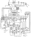
- Fig. 1 shows a hydrostatic-mechanical Power split power shift transmission, the hydrostatic branch from the hydrostatic actuator (HG) exists. This is done through an electronic Control device (ST) controlled by this via a electrical-hydraulic control valve pair (HGV) one Position-proportional hydraulic control cylinder (HGZ) actuated, so that this the setting angle and thus the Displacement of the hydraulic actuator (HG) determined.
- ST electronic Control device
- HGV electrical-hydraulic control valve pair
- HGZ Position-proportional hydraulic control cylinder
- the Presence of this speed ratio from the signals of the speed sensors (S1, S2) in the electronic Control device (ST) is determined by the Control device (ST) the electrohydraulic Third gear valve (V3) actuates the 3rd gear clutch (K3) engage hydraulically, the determined Speed ratio ensures that the gear parts of the Third gear clutch (K3) synchronized before clutching circulate.
- the torque is released on the clutch (K2) thereby determined that when in the separating direction Coupling (K2) constantly the signal of the Clutch position sensor (KS2) on an occurring Position change monitored by the control device (ST) becomes.
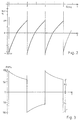
- Fig. 3 shows the pressure conditions in the hydrostatic branch.
- the two pressures (P1, P2) behave on both sides of the switching point to each other like that Control ratio.
- Fig. 4 is schematic, i.e. enlarged in the switching range, the dependence of the displacement volume and the associated volume Positions of the control means of the displacer volume Upshift shown.
- the old displacement volume (Valt), that prevails when engaging is about the leak volume (DValt) larger than the theoretical displacement volume (Vth).
- the new displacement volume (Vneu), where the old gearbox is unloaded, is by one, the leakage volume factor (k) larger leak volume difference (DValt x k) smaller than that theoretical displacement volume (Vth).
- the old ones and the new shot (Salt, Sneu) by a smaller one or a larger amount higher or lower than that theoretical position (Sth).
- the Leakage volume factor is generally greater than 1, since in the old and in the new condition other pressure conditions prevail, which to the Lead differences.
- FIG. 5 is schematic, enlarged in Clutch adjustment range, the dependency of the Displacement volume and the associated positions of the Displacement control means shown when downshifting.
- the old displacement volume (Valt ') the is controlled when engaging the lower gearbox to a larger loss volume (DValt ') below the theoretical Displacement (Vth) lies as the new displacement (Vneu ') after the downshift, which relieves the load of the old gearbox is required above the theoretical Displacement volume (Vth).
- This leakage loss (DVnew ') is the quotient of the old leakage loss (DValt ') and the leak volume factor (k).
- the Clutch position sensors (KS2, KS3) are for example commercially available rotary potentiometers, which are connected to the Actuating shafts of the swivel claws are arranged. Of the Working range of this potentiometer is expediently something larger than the swivel angle of the swivel claws between the engaged and disengaged state of the connected Couplings.
- the two sensor signal values of the Voltage-fed potentiometers in the Clutch settings occur each time from the Control device stored and as comparison values used, taking into account a tolerance value appropriately becomes.
Landscapes
- Engineering & Computer Science (AREA)
- General Engineering & Computer Science (AREA)
- Mechanical Engineering (AREA)
- Control Of Transmission Device (AREA)
- Hydraulic Clutches, Magnetic Clutches, Fluid Clutches, And Fluid Joints (AREA)
- Control Of Fluid Gearings (AREA)
Description
- Fig. 1
- zeigt ein Mehrganggetriebeschema;
- Fig. 2
- zeigt die hydrostatischen Leistungsanteile des Getriebes;
- Fig. 3
- zeigt die hydrostatischen Druckverhältnisse des Getriebes;
- Fig. 4
- zeigt ein Hochschalt-Einstelldiagramm;
- Fig. 5
- zeigt ein Herunterschalt-Einstelldiagramm.
Claims (8)
- Verfahren zur Steuerung eines hydrostatischen Verstellgetriebes (HG) eines hydrostatisch-mechanisch stufenlos leistungsverzweigten Lastschaltgetriebes bei dem zu einem Gangwechsel ein Verdrängervolumen jeweils so lange geändert wird, bis ein vorgegebenes Drehzahlverhältnis einer Getriebeeingangswellendrehzahl zu einer Ausgangswellendrehzahl vorliegt, wonach ein Einschalten einer Kupplung (K2, K3) eines neuen Ganges erfolgt, und dann das Verdrängervolumen bezüglich eines theoretischen Verdrängervolumens (Vth) in Richtung auf ein neues Verdrängervolumen (Vneu, V'neu) geändert wird, bei dem die Kupplung (K3, K2) des jeweils noch mitlaufenden, vorher wirksamen Ganges entlastet wird, wonach diese ausgerückt wird,
dadurch gekennzeichnet, daß während dieser Änderung des Verdrängervolumens die Kupplung (K3, K2) des jeweils noch mitlaufenden, vorher wirksamen Ganges in Ausrückrichtung angesteuert wird und dabei ein Kupplungsstellungssignal laufend darauf überwacht wird, ob ein Ausrücken beginnt, und wenn dies der Fall ist, das erreichte Verdrängervolumen konstant gehalten wird, bis ein vollständiges Ausrücken der betreffenden Kupplung (K3, K2) durch das Kupplungsstellungssignal gemeldet wird. - Verfahren nach Anspruch 1, dadurch gekennzeichnet, daß während der Änderung des Verdrängervolumens die Kupplung (K3) intermittierend jeweils für einen kurzen, zu einer Bewegung in die Ausrückerichtung ausreichenden, Zeitraum angesteuert wird und davor jeweils das Kupplungsstellungssignal gespeichert und danach das jeweilige Kupplungsstellungssignal mit dem gespeicherten Kupplungsstellungssignal verglichen wird und, wenn dieses um einen vorgegebenen ersten Vergleichswert davon abweicht, die Kupplung (K3) solange ausrückend angesteuert wird, bis das jeweilige Kupplungsstellungssignal einen zweiten vorgegebenen Vergleichswert erreicht hat, der das vollständige Ausrücken der Kupplung (K3) signalisiert.
- Vorrichtung zur Durchführung des Verfahrens nach einem der vorstehenden Ansprüchen, dadurch gekennzeichnet, daß die Kupplungen (K2, K3) mit Kupplungsstellungsensoren (KS2, KS3) verbunden sind, deren Kupplungsstellungsignale einer elektronischen Steuervorrichtung (ST) zugeführt sind, die diese verfahrensgemäß auswertet.
- Vorrichtung nach Anspruch 3, dadurch gekennzeichnet, daß die Kupplungsstellungssensoren (KS2, KS3) Drehpotentiometer sind, die jeweils mit einer Kupplungsstellerwelle der zugehörigen Kupplung (K2, K3) verbunden sind und deren Winkelstellbereich jeweils größer als ein Schwenkbereich der Kupplungsstellerwelle zwischen den ein- und ausgerückten Kupplungsstellungen ist.
- Vorrichtung nach Anspruch 4, dadurch gekennzeichnet, daß in der Steuervorrichtung (ST) jeweils die Kupplungsstellungs-Sensorsignale, die in den ein- und ausgerückten Kupplungsstellungen vorliegen, als die Vergleichswerte eingespeichert sind, die unter Berücksichtigung von Toleranzwerten den verfahrensgemäßen Vergleichen dienen.
- Vorrichtung nach Anspruch 3, dadurch gekennzeichnet, daß das Verstellgetriebe (HG) mit einem Proportionalventil (HGZ) gesteuert verbunden ist, das von einem elektrohydraulischen Steuerventilsatz (HGV) beaufschlagbar ist, das elektrisch von der elektronischen Steuervorrichtung (ST) beaufschlagt ist, die mittels eines Steuerprogrammes verfahrensgemäß den Steuerventilsatz (HGV) und die Kupplungen (K2, K3) mittels elektro-hydraulischer Ventile (V2, V3) ansteuert.
- Vorrichtung nach Anspruch 6, dadurch gekennzeichnet, daß das Proportionalventil (HGZ) von der Steuervorrichtung (ST) mit einem jeweils vorgegebenen Strom beaufschlagt ist, proportional zu dem dieses jeweils eingestellt ist oder an dem Proportionalventil (HGZ) oder an dem Verstellgetriebe (HG) ein Stellungssensor (P) angeordnet ist, dessen Stellungssignal der Steuervorrichtung (ST) zugeführt ist, das als ein Rückkoppelsignal in einer Regelschleife jeweils zur Einstellung des verfahrensgemäß bestimmten Verdrängervolumens dient.
- Vorrichtung nach Anspruch 6, dadurch gekennzeichnet, daß an der Ein- und Ausgangswelle des Verstellgetriebes (HG) Tachometersensoren (S1, S2) angeordnet sind, deren Signale von der Steuervorrichtung (ST) jeweils zur Ermittlung eines Synchronzustandes an einer zu schließenden Kupplung (K2, K3) überwacht werden.
Applications Claiming Priority (2)
| Application Number | Priority Date | Filing Date | Title |
|---|---|---|---|
| DE4433488A DE4433488A1 (de) | 1994-09-20 | 1994-09-20 | Steuerung einer Verdrängermaschine eines hydrostatisch-mechanischen Lastschaltgetriebes |
| DE4433488 | 1994-09-20 |
Publications (3)
| Publication Number | Publication Date |
|---|---|
| EP0703386A2 EP0703386A2 (de) | 1996-03-27 |
| EP0703386A3 EP0703386A3 (de) | 1997-04-23 |
| EP0703386B1 true EP0703386B1 (de) | 1998-11-11 |
Family
ID=6528691
Family Applications (1)
| Application Number | Title | Priority Date | Filing Date |
|---|---|---|---|
| EP95113359A Expired - Lifetime EP0703386B1 (de) | 1994-09-20 | 1995-08-25 | Steuerung einer Verdrängermaschine eines hydrostatisch-mechanischen Lastschaltgetriebes |
Country Status (4)
| Country | Link |
|---|---|
| US (1) | US5605515A (de) |
| EP (1) | EP0703386B1 (de) |
| JP (1) | JPH08105509A (de) |
| DE (2) | DE4433488A1 (de) |
Cited By (1)
| Publication number | Priority date | Publication date | Assignee | Title |
|---|---|---|---|---|
| DE10115128A1 (de) * | 2001-03-27 | 2002-10-10 | Zahnradfabrik Friedrichshafen | Leistungsverzweigungsgetriebe |
Families Citing this family (8)
| Publication number | Priority date | Publication date | Assignee | Title |
|---|---|---|---|---|
| DE4431864A1 (de) * | 1994-09-07 | 1996-03-14 | Zahnradfabrik Friedrichshafen | Fahrantrieb |
| EP0897493B1 (de) * | 1996-04-30 | 2000-03-15 | Steyr-Daimler-Puch Aktiengesellschaft | Verfahren zum steuern der kupplungen eines hydrostatisch-mechanischen leistungsverzweigungsgetriebes |
| US7530914B2 (en) * | 2005-06-03 | 2009-05-12 | Caterpillar Inc. | Hydromechanical transmission |
| US7530913B2 (en) * | 2005-06-03 | 2009-05-12 | Caterpillar Inc. | Multi-range hydromechanical transmission |
| KR101087843B1 (ko) * | 2006-07-06 | 2011-11-30 | 가부시끼 가이샤 구보다 | 변속 전동 장치 |
| JP5126628B2 (ja) * | 2010-04-02 | 2013-01-23 | アイシン・エィ・ダブリュ株式会社 | 制御装置 |
| CN105114606B (zh) * | 2015-09-16 | 2016-10-12 | 湖南省农友机械集团有限公司 | 一种双动力输入式三挡履带车辆变速器 |
| CN105114587B (zh) * | 2015-09-16 | 2016-05-25 | 湖南省农友机械集团有限公司 | 一种机械直连与静液压无级并联三速式双动力输入装置 |
Family Cites Families (7)
| Publication number | Priority date | Publication date | Assignee | Title |
|---|---|---|---|---|
| DE3667836D1 (de) * | 1986-02-24 | 1990-02-01 | Shimadzu Corp | Hydromechanisches getriebe. |
| DE3871561D1 (de) * | 1987-03-09 | 1992-07-09 | Hydromatik Gmbh | Antriebseinrichtung, bestehend aus einem antriebsmotor wechselnder drehzahl, einem verstellbaren hydrostatischen getriebe und einer schaltbaren einrichtung. |
| DE3838767A1 (de) * | 1987-05-12 | 1989-06-08 | Jarchow Friedrich | Stufenlos wirkendes hydrostatisch-mechanisches lastschaltgetriebe mit hoher schaltqualitaet |
| WO1989012188A1 (fr) * | 1988-05-31 | 1989-12-14 | Kabushiki Kaisha Komatsu Seisakusho | Transmission mecanique-hydraulique intermediaire et procede de commande de cette transmission |
| DE4109884A1 (de) * | 1991-03-26 | 1992-10-01 | Claas Ohg | Steuerung einer verdraengermaschine eines hydrostatisch-mechanischen lastschaltgetriebes |
| DE4339864A1 (de) * | 1992-11-23 | 1994-07-21 | Michael Meyerle | Stufenloses hydrostatisch-mechanisches Leistungsverzweigungsgetriebe, insbesondere für Kraftfahrzeuge |
| GB2277625B (en) * | 1993-04-30 | 1996-08-28 | Kidde Fire Protection Ltd | Particle detecting apparatus and systems |
-
1994
- 1994-09-20 DE DE4433488A patent/DE4433488A1/de not_active Withdrawn
-
1995
- 1995-08-25 EP EP95113359A patent/EP0703386B1/de not_active Expired - Lifetime
- 1995-08-25 DE DE59504207T patent/DE59504207D1/de not_active Expired - Fee Related
- 1995-09-08 JP JP7266063A patent/JPH08105509A/ja active Pending
- 1995-09-14 US US08/528,495 patent/US5605515A/en not_active Expired - Fee Related
Cited By (1)
| Publication number | Priority date | Publication date | Assignee | Title |
|---|---|---|---|---|
| DE10115128A1 (de) * | 2001-03-27 | 2002-10-10 | Zahnradfabrik Friedrichshafen | Leistungsverzweigungsgetriebe |
Also Published As
| Publication number | Publication date |
|---|---|
| EP0703386A2 (de) | 1996-03-27 |
| US5605515A (en) | 1997-02-25 |
| EP0703386A3 (de) | 1997-04-23 |
| JPH08105509A (ja) | 1996-04-23 |
| DE4433488A1 (de) | 1996-03-21 |
| DE59504207D1 (de) | 1998-12-17 |
Similar Documents
| Publication | Publication Date | Title |
|---|---|---|
| EP0505688B1 (de) | Steuerung einer Verdrängermaschine eines hydrostatisch-mechanischen Lastschaltgetriebes | |
| EP0650564B1 (de) | Getriebeeinheit zur anordnung zwischen einem antriebsmotor und einem verbraucher | |
| EP0478945B1 (de) | Verfahren zum selbsttätigen Schalten mittels Druckmittel-Hilfskraft eines Mehrwege-Zahnräderwechselgetriebes | |
| DE4400701C2 (de) | Übertragungsvorrichtung zur Übertragung einer Motorleistung auf Antriebsräder eines Fahrzeuges | |
| DE68916840T2 (de) | Druckluftsteuerung für ein Mehrbereichsverbundgetriebe. | |
| DE102004043017B4 (de) | Steuerungssystem eines hydromechanischen Getriebes | |
| EP0464413B1 (de) | Hydrostatisch-mechanisch leistungsverzweigtes Mehrgang-Lastschaltgetriebe | |
| DE69702328T2 (de) | Hydraulisches Steuersystem für Automatikgetriebe mit Doppelkupplung | |
| DE3851010T2 (de) | Stufenloses Geschwindigkeitswechselgetriebe. | |
| DE3207938C2 (de) | Unter Last schaltbare mechanische Getriebeanordnung | |
| DE3241140A1 (de) | Hydraulische uebertragungseinrichtung fuer ein fahrzeug | |
| DE69627224T2 (de) | Hydraulische Steuerung für eine Synchronisiereinrichtung | |
| DE102006004223A1 (de) | Verfahren und Mittel zum Schalten einer hydromechanischen Kraftübertragung | |
| EP0703386B1 (de) | Steuerung einer Verdrängermaschine eines hydrostatisch-mechanischen Lastschaltgetriebes | |
| DE1291587B (de) | Hydraulische Steuerungsvorrichtung fuer ein mehrstufiges, mittels hydraulisch betaetigter Reibungskupplungen geschaltetes Zahnraederwechsel- und -wendegetriebe | |
| DE3433495C2 (de) | ||
| DE102006016397A1 (de) | Getriebe für ein Kraftfahrzeug | |
| DE4017961A1 (de) | Steuersystem fuer ein lastschaltbares doppel-kupplungsgetriebe | |
| DE112011100496T5 (de) | Hydraulische Steuervorrichtung für Automatikgetriebe | |
| DE2901543C2 (de) | Schalteinrichtung für die Übersetzungseinstellung eines hydrostatisch-mechanischen Verbundgetriebes | |
| EP0545298A1 (de) | Fahrzeugantriebsstrang mit hydraulisch gesteuertem Schaltgetriebe | |
| DE102004041525A1 (de) | Lastschaltgetriebe und Schaltverfahren dafür | |
| DE60013292T2 (de) | Schaltsynchronisation die ein abfallendes Drehmoment berücksichtigt | |
| DE19751456A1 (de) | Verfahren zum Schalten eines Doppelkupplungsgetriebes | |
| DE60304698T2 (de) | Steuerverfahren für ein automatisches getriebe |
Legal Events
| Date | Code | Title | Description |
|---|---|---|---|
| PUAI | Public reference made under article 153(3) epc to a published international application that has entered the european phase |
Free format text: ORIGINAL CODE: 0009012 |
|
| AK | Designated contracting states |
Kind code of ref document: A2 Designated state(s): DE FR GB IT |
|
| PUAL | Search report despatched |
Free format text: ORIGINAL CODE: 0009013 |
|
| AK | Designated contracting states |
Kind code of ref document: A3 Designated state(s): DE FR GB IT |
|
| 17P | Request for examination filed |
Effective date: 19970613 |
|
| GRAG | Despatch of communication of intention to grant |
Free format text: ORIGINAL CODE: EPIDOS AGRA |
|
| GRAG | Despatch of communication of intention to grant |
Free format text: ORIGINAL CODE: EPIDOS AGRA |
|
| GRAH | Despatch of communication of intention to grant a patent |
Free format text: ORIGINAL CODE: EPIDOS IGRA |
|
| 17Q | First examination report despatched |
Effective date: 19971212 |
|
| GRAH | Despatch of communication of intention to grant a patent |
Free format text: ORIGINAL CODE: EPIDOS IGRA |
|
| GRAA | (expected) grant |
Free format text: ORIGINAL CODE: 0009210 |
|
| AK | Designated contracting states |
Kind code of ref document: B1 Designated state(s): DE FR GB IT |
|
| REF | Corresponds to: |
Ref document number: 59504207 Country of ref document: DE Date of ref document: 19981217 |
|
| GBT | Gb: translation of ep patent filed (gb section 77(6)(a)/1977) |
Effective date: 19981203 |
|
| ET | Fr: translation filed | ||
| PLBE | No opposition filed within time limit |
Free format text: ORIGINAL CODE: 0009261 |
|
| STAA | Information on the status of an ep patent application or granted ep patent |
Free format text: STATUS: NO OPPOSITION FILED WITHIN TIME LIMIT |
|
| 26N | No opposition filed | ||
| REG | Reference to a national code |
Ref country code: GB Ref legal event code: IF02 |
|
| PG25 | Lapsed in a contracting state [announced via postgrant information from national office to epo] |
Ref country code: IT Free format text: LAPSE BECAUSE OF NON-PAYMENT OF DUE FEES;WARNING: LAPSES OF ITALIAN PATENTS WITH EFFECTIVE DATE BEFORE 2007 MAY HAVE OCCURRED AT ANY TIME BEFORE 2007. THE CORRECT EFFECTIVE DATE MAY BE DIFFERENT FROM THE ONE RECORDED. Effective date: 20050825 |
|
| PGFP | Annual fee paid to national office [announced via postgrant information from national office to epo] |
Ref country code: DE Payment date: 20070710 Year of fee payment: 13 |
|
| PGFP | Annual fee paid to national office [announced via postgrant information from national office to epo] |
Ref country code: GB Payment date: 20070828 Year of fee payment: 13 |
|
| PGFP | Annual fee paid to national office [announced via postgrant information from national office to epo] |
Ref country code: FR Payment date: 20070821 Year of fee payment: 13 |
|
| GBPC | Gb: european patent ceased through non-payment of renewal fee |
Effective date: 20080825 |
|
| REG | Reference to a national code |
Ref country code: FR Ref legal event code: ST Effective date: 20090430 |
|
| PG25 | Lapsed in a contracting state [announced via postgrant information from national office to epo] |
Ref country code: FR Free format text: LAPSE BECAUSE OF NON-PAYMENT OF DUE FEES Effective date: 20080901 Ref country code: DE Free format text: LAPSE BECAUSE OF NON-PAYMENT OF DUE FEES Effective date: 20090303 |
|
| PG25 | Lapsed in a contracting state [announced via postgrant information from national office to epo] |
Ref country code: GB Free format text: LAPSE BECAUSE OF NON-PAYMENT OF DUE FEES Effective date: 20080825 |