EP0703202A1 - Verfahren zur Herstellung von Ethylbenzol - Google Patents
Verfahren zur Herstellung von Ethylbenzol Download PDFInfo
- Publication number
- EP0703202A1 EP0703202A1 EP95203075A EP95203075A EP0703202A1 EP 0703202 A1 EP0703202 A1 EP 0703202A1 EP 95203075 A EP95203075 A EP 95203075A EP 95203075 A EP95203075 A EP 95203075A EP 0703202 A1 EP0703202 A1 EP 0703202A1
- Authority
- EP
- European Patent Office
- Prior art keywords
- stream
- benzene
- reaction
- reactor
- ethylbenzene
- Prior art date
- Legal status (The legal status is an assumption and is not a legal conclusion. Google has not performed a legal analysis and makes no representation as to the accuracy of the status listed.)
- Granted
Links
- YNQLUTRBYVCPMQ-UHFFFAOYSA-N CCc1ccccc1 Chemical compound CCc1ccccc1 YNQLUTRBYVCPMQ-UHFFFAOYSA-N 0.000 description 1
Images


Classifications
-
- C—CHEMISTRY; METALLURGY
- C07—ORGANIC CHEMISTRY
- C07C—ACYCLIC OR CARBOCYCLIC COMPOUNDS
- C07C15/00—Cyclic hydrocarbons containing only six-membered aromatic rings as cyclic parts
- C07C15/02—Monocyclic hydrocarbons
- C07C15/067—C8H10 hydrocarbons
- C07C15/073—Ethylbenzene
-
- B—PERFORMING OPERATIONS; TRANSPORTING
- B01—PHYSICAL OR CHEMICAL PROCESSES OR APPARATUS IN GENERAL
- B01J—CHEMICAL OR PHYSICAL PROCESSES, e.g. CATALYSIS OR COLLOID CHEMISTRY; THEIR RELEVANT APPARATUS
- B01J19/00—Chemical, physical or physico-chemical processes in general; Their relevant apparatus
- B01J19/0053—Details of the reactor
- B01J19/0073—Sealings
-
- B—PERFORMING OPERATIONS; TRANSPORTING
- B01—PHYSICAL OR CHEMICAL PROCESSES OR APPARATUS IN GENERAL
- B01J—CHEMICAL OR PHYSICAL PROCESSES, e.g. CATALYSIS OR COLLOID CHEMISTRY; THEIR RELEVANT APPARATUS
- B01J19/00—Chemical, physical or physico-chemical processes in general; Their relevant apparatus
- B01J19/26—Nozzle-type reactors, i.e. the distribution of the initial reactants within the reactor is effected by their introduction or injection through nozzles
-
- F—MECHANICAL ENGINEERING; LIGHTING; HEATING; WEAPONS; BLASTING
- F28—HEAT EXCHANGE IN GENERAL
- F28F—DETAILS OF HEAT-EXCHANGE AND HEAT-TRANSFER APPARATUS, OF GENERAL APPLICATION
- F28F9/00—Casings; Header boxes; Auxiliary supports for elements; Auxiliary members within casings
- F28F9/02—Header boxes; End plates
- F28F9/0229—Double end plates; Single end plates with hollow spaces
-
- B—PERFORMING OPERATIONS; TRANSPORTING
- B01—PHYSICAL OR CHEMICAL PROCESSES OR APPARATUS IN GENERAL
- B01J—CHEMICAL OR PHYSICAL PROCESSES, e.g. CATALYSIS OR COLLOID CHEMISTRY; THEIR RELEVANT APPARATUS
- B01J2219/00—Chemical, physical or physico-chemical processes in general; Their relevant apparatus
- B01J2219/00049—Controlling or regulating processes
- B01J2219/00051—Controlling the temperature
- B01J2219/00054—Controlling or regulating the heat exchange system
- B01J2219/00056—Controlling or regulating the heat exchange system involving measured parameters
- B01J2219/00058—Temperature measurement
- B01J2219/0006—Temperature measurement of the heat exchange medium
-
- B—PERFORMING OPERATIONS; TRANSPORTING
- B01—PHYSICAL OR CHEMICAL PROCESSES OR APPARATUS IN GENERAL
- B01J—CHEMICAL OR PHYSICAL PROCESSES, e.g. CATALYSIS OR COLLOID CHEMISTRY; THEIR RELEVANT APPARATUS
- B01J2219/00—Chemical, physical or physico-chemical processes in general; Their relevant apparatus
- B01J2219/00049—Controlling or regulating processes
- B01J2219/00051—Controlling the temperature
- B01J2219/00054—Controlling or regulating the heat exchange system
- B01J2219/00056—Controlling or regulating the heat exchange system involving measured parameters
- B01J2219/00058—Temperature measurement
- B01J2219/00063—Temperature measurement of the reactants
-
- B—PERFORMING OPERATIONS; TRANSPORTING
- B01—PHYSICAL OR CHEMICAL PROCESSES OR APPARATUS IN GENERAL
- B01J—CHEMICAL OR PHYSICAL PROCESSES, e.g. CATALYSIS OR COLLOID CHEMISTRY; THEIR RELEVANT APPARATUS
- B01J2219/00—Chemical, physical or physico-chemical processes in general; Their relevant apparatus
- B01J2219/00049—Controlling or regulating processes
- B01J2219/00051—Controlling the temperature
- B01J2219/00074—Controlling the temperature by indirect heating or cooling employing heat exchange fluids
- B01J2219/00076—Controlling the temperature by indirect heating or cooling employing heat exchange fluids with heat exchange elements inside the reactor
- B01J2219/00085—Plates; Jackets; Cylinders
-
- B—PERFORMING OPERATIONS; TRANSPORTING
- B01—PHYSICAL OR CHEMICAL PROCESSES OR APPARATUS IN GENERAL
- B01J—CHEMICAL OR PHYSICAL PROCESSES, e.g. CATALYSIS OR COLLOID CHEMISTRY; THEIR RELEVANT APPARATUS
- B01J2219/00—Chemical, physical or physico-chemical processes in general; Their relevant apparatus
- B01J2219/00049—Controlling or regulating processes
- B01J2219/00051—Controlling the temperature
- B01J2219/00074—Controlling the temperature by indirect heating or cooling employing heat exchange fluids
- B01J2219/00087—Controlling the temperature by indirect heating or cooling employing heat exchange fluids with heat exchange elements outside the reactor
- B01J2219/00094—Jackets
-
- B—PERFORMING OPERATIONS; TRANSPORTING
- B01—PHYSICAL OR CHEMICAL PROCESSES OR APPARATUS IN GENERAL
- B01J—CHEMICAL OR PHYSICAL PROCESSES, e.g. CATALYSIS OR COLLOID CHEMISTRY; THEIR RELEVANT APPARATUS
- B01J2219/00—Chemical, physical or physico-chemical processes in general; Their relevant apparatus
- B01J2219/00049—Controlling or regulating processes
- B01J2219/00051—Controlling the temperature
- B01J2219/00074—Controlling the temperature by indirect heating or cooling employing heat exchange fluids
- B01J2219/00087—Controlling the temperature by indirect heating or cooling employing heat exchange fluids with heat exchange elements outside the reactor
- B01J2219/00103—Controlling the temperature by indirect heating or cooling employing heat exchange fluids with heat exchange elements outside the reactor in a heat exchanger separate from the reactor
-
- B—PERFORMING OPERATIONS; TRANSPORTING
- B01—PHYSICAL OR CHEMICAL PROCESSES OR APPARATUS IN GENERAL
- B01J—CHEMICAL OR PHYSICAL PROCESSES, e.g. CATALYSIS OR COLLOID CHEMISTRY; THEIR RELEVANT APPARATUS
- B01J2219/00—Chemical, physical or physico-chemical processes in general; Their relevant apparatus
- B01J2219/00049—Controlling or regulating processes
- B01J2219/00051—Controlling the temperature
- B01J2219/00159—Controlling the temperature controlling multiple zones along the direction of flow, e.g. pre-heating and after-cooling
-
- B—PERFORMING OPERATIONS; TRANSPORTING
- B01—PHYSICAL OR CHEMICAL PROCESSES OR APPARATUS IN GENERAL
- B01J—CHEMICAL OR PHYSICAL PROCESSES, e.g. CATALYSIS OR COLLOID CHEMISTRY; THEIR RELEVANT APPARATUS
- B01J2219/00—Chemical, physical or physico-chemical processes in general; Their relevant apparatus
- B01J2219/00049—Controlling or regulating processes
- B01J2219/00162—Controlling or regulating processes controlling the pressure
-
- Y—GENERAL TAGGING OF NEW TECHNOLOGICAL DEVELOPMENTS; GENERAL TAGGING OF CROSS-SECTIONAL TECHNOLOGIES SPANNING OVER SEVERAL SECTIONS OF THE IPC; TECHNICAL SUBJECTS COVERED BY FORMER USPC CROSS-REFERENCE ART COLLECTIONS [XRACs] AND DIGESTS
- Y02—TECHNOLOGIES OR APPLICATIONS FOR MITIGATION OR ADAPTATION AGAINST CLIMATE CHANGE
- Y02P—CLIMATE CHANGE MITIGATION TECHNOLOGIES IN THE PRODUCTION OR PROCESSING OF GOODS
- Y02P20/00—Technologies relating to chemical industry
- Y02P20/141—Feedstock
-
- Y—GENERAL TAGGING OF NEW TECHNOLOGICAL DEVELOPMENTS; GENERAL TAGGING OF CROSS-SECTIONAL TECHNOLOGIES SPANNING OVER SEVERAL SECTIONS OF THE IPC; TECHNICAL SUBJECTS COVERED BY FORMER USPC CROSS-REFERENCE ART COLLECTIONS [XRACs] AND DIGESTS
- Y02—TECHNOLOGIES OR APPLICATIONS FOR MITIGATION OR ADAPTATION AGAINST CLIMATE CHANGE
- Y02P—CLIMATE CHANGE MITIGATION TECHNOLOGIES IN THE PRODUCTION OR PROCESSING OF GOODS
- Y02P20/00—Technologies relating to chemical industry
- Y02P20/50—Improvements relating to the production of bulk chemicals
- Y02P20/582—Recycling of unreacted starting or intermediate materials
Definitions
- This invention is directed to a process for producing ethylbenzene, in which process reaction heat is recovered in high efficiency.
- ethylbenzene by the traditional aluminum chloride (AlCl3) catalyzed reaction of ethylene and benzene has been in commercial use for decades.
- Ethylbenzene is used in large quantities for the manufacture of styrene monomer, the raw material for polystyrene.
- the catalyst is a liquid, AlCl3, complex.
- the reaction is carried out in a heterogeneous liquid medium composes of the catalyst complex and a mixture of ethylated benzenes and results in a two-phase liquid product: (1) the liquid AlCl3 complex (separated and recycled to the alkylator), and (2) a mixture of unreacted benzene and reaction products such as ethylbenzene, diethylbenzene and higher polyethylbenzenes.
- the overall reaction can be expressed simply as: The actual chemistry involved is complex.
- the alkylation is complicated by the occurrence of minor side reaction such as cracking and polymerization.
- minor side reaction such as cracking and polymerization.
- polyethylbenzenes As illustrated by the equation above, the first alkyl group formed activates the aromatic nucleus so that the second alkylation proceeds more readily than the first and so on, at least until steric hindrance intervenes, although hexaethylbenzene is quite readily formed. This results in a mixture of mono, di, tri, and higher ethylbenzenes together with unreacted benzene.
- reaction is reversible, that is, reversible in the sense that diethylbenzene, for example, will react under the influence of AlCl3 to form monoethylbenzene:
- this transalkylation or reshuffling of ethyl groups among the aromatic rings takes a given reaction mixture to an equilibrium composition that is dependent only on the ratio of ethyl group to benzene rings present. It is these transalkylation reactions that permit virtually all the ethylene and benzene fed to the reactor system to be eventually converted to monoethylbenzene.
- both the alkylation and transalkylation steps are carried out in a single back-mix reactor using relatively low contact times and low temperatures (30 to 60 min. and 110°C to 165°C).
- the conventional process also uses relatively high AlCl3 catalyst concentrations. For this reason, the catalyst must be separated from the reaction product and recycled to the reactor.
- U.S. Patent 3,448,161 teaches the use of short contact times (2 min.) and temperatures up to 250°C.
- U.S. Patent 3,766,290 discloses the use of catalyst concentrations below the level that requires catalyst recycle. The advantages of separate alkylation and transalkylation reactors are revealed in U.S. Patent 3,848,012.
- U.S. Patent 4,179,473 U.S. Patent 3,501,536 teaches the use of a reactor with heat exchange tubes and a plurality of conduits that carry hydrocarbon reactants into a reactor space for intimate mixing and cooling of reactants and catalyst, the reactants entering through a series of spaced openings to the tubes which jet the reactants into an upward spiraling flow around the heat exchange tubes.
- U.S. Patent 4,179,473 U.S. Patent 3,501,536 teaches the use of a reactor with heat exchange tubes and a plurality of conduits that carry hydrocarbon reactants into a reactor space for intimate mixing and cooling of reactants and catalyst, the reactants entering through a series of spaced openings to the tubes which jet the reactants into an upward spiraling flow around the heat exchange tubes.
- Patent 3,817,708 discloses a heat exchanger for use in an alkylation unit in which a heat transfer medium flows through U-tubes while an alkylation catalytic acid flows through the remaining space within a cylindrical shell that houses the U-tubes, the bends in the U-tubes approaching each other near the center of the shell in an adjacent, spaced apart, non-overlapping relationship. All of these processes have certain disadvantages which are overcome by the present invention.
- the present invention in one embodiment, teaches a process for producing monoethylbenzene by the reaction of ethylene and benzene and takes advantage of the fundamental chemistries of the two major reaction steps, alkylation and transalkylation, to improve the efficiency of known ethylbenzene production processes. Further, while the improved process of the present invention can be readily applied to new production facilities, it is also applicable to retrofitting into and increasing the efficiency of existing plants.
- the present invention relates to a process for producing ethylbenzene, which process comprises: feeding ethylene, catalyst, and benzene into reaction tubes in an alkylation reactor vessel in which they react exothermically producing a first stream with benzene, catalyst, ethylbenzene and polyethylbenzenes as reaction products; flowing the first stream into a transalkylation reactor producing a second stream with a higher ethylbenzene content and a lower polyethylbenzene content than the first stream, the second stream containing catalyst, ethylbenzene, benzene, and polyethylbenzene; flowing the second stream to separation means for separating out its component, including ethylbenzene; flowing a heat transfer medium in heat exchange relationship with the reaction tubes in the reactor vessel to recover heat produced by the reaction of the ethylene and benzene, and flowing the thus heated transfer medium to the separation means to provide heat for operating the separation means.
- the present invention may use a turbulent flow alkylator reactor with reaction heat recovery.
- a turbulent flow alkylator reactor with reaction heat recovery.
- each of two reactor heads allow for gaseous reactants to be injected into a liquid stream at the start of each pass through a reaction tube.
- One or more reaction tubes can be included in any particular pass through the reactor and any desired number of passes may be employed. All tubes of a given pass can be fed with gas from a common gas chamber, and a separate gas chamber can be used for each pass of the reactor. Gas flows from the gas chambers through gas spargers, and into the reaction tubes where it turbulently contacts the liquid stream.
- each tube of a given pass one gas sparger protrudes axially down into the tube for a short distance. This configuration allows each tube of a given pass to be individually fed with gas.
- the entire liquid feed stream enters the reactor at the start of the first pass.
- the ends of the reaction tubes open into liquid chambers.
- gas is sparged into the liquid within a reactor tube at the start of each pass.
- This reactor allows relatively fast and highly exothermic alkylation reactions to be carried out in a manner such that the heat of reaction is used directly to drive and ethylbenzene finishing train or to heat other streams in a process.
- the reactor is of multi-pass, tube-in-shell horizontal design with ethylbenzene finishing tower bottoms applied to the shell as a heat transfer medium and an alkylation carried out in the tubes.
- the reactor shell serves as a tower reboiler. It is preferred that linear velocities inside the tubes are such that the reactor operates near the plug-flow region. A plurality of ethylene injectors help to control the reaction exotherm. Contact times of less than one minute are possible.
- processes are employed which utilize apparatuses which provide for a uniform feeding of liquid reactants to a plurality of reaction tubes of a particular pass through the reactor. This is accomplished by adjusting flow and design parameters including sparger disposition, dimensions, and reaction tube disposition and dimensions.
- reaction temperatures greater than 200°C are achieved and reaction pressures are sufficient to maintain aromatic hydrocarbons in the liquid phase.
- the process comprises: feeding first reactant material, consisting of ethylene, catalyst, and benzene, into a first chamber of a reactor vessel, the reactor vessel having a first end, a second end, and a reaction product outlet from which products of the reaction flow from the reactor vessel, flowing the first reactant material from the first chamber turbulently into a hollow reaction tube having an exterior surface, the reaction tube communicating with the first chamber and extending between the first and second ends of the reactor vessel, feeding second reactant material through a hollow sparger into the reaction tube, the hollow sparger partially extending into the reaction tube, the second material flowing turbulently into the reaction tube, the reaction tube communicating with the reaction product outlet so that produces of the reaction of the first and second reactant material flow from the reaction tube and out of the reactor vessel through the reaction product outlet.
- first reactant material consisting of ethylene, catalyst, and benzene
- Another embodiment of the process of the present invention involves: feeding first reactant material, consisting of ethylene, catalyst, and benzene, into a first chamber of a reactor vessel, the reactor vessel having a first end, a second end, and a reaction product outlet from which products of the reaction flow from the reactor vessel, flowing the first reactant material from the first chamber at the first end of the reactor vessel uniformly and turbulently into a plurality of hollow reaction tubes, each tube having an interior and an exterior surface and communicating with the first chamber, each tube extending between the first chamber and the second end of the reactor vessel, feeding second reactant material through hollow spargers into the reaction tubes, one sparger disposed partially in each reaction tube, the second reactant material flowing turbulently through the spargers and into the reaction tubes, flowing a heat transfer medium through a heat transfer inlet into the reactor so that it contacts the exterior surfaces of the reaction tubes in a heat exchange relationship therewith, flowing the heat transfer medium through a heat transfer outlet out of the reactor, and flowing products of reaction from the reaction tubes through the reaction product outlet with which the
- a reactor for a reaction of reactant materials comprising: a hollow reactor vessel having a first end, a second end, and a reaction product outlet from which products of the reaction flow from the reactor vessel, at least one reaction tube having an interior, an exterior surface, a first end and a second end and mounted within the reactor vessel extending from the first end of the reactor vessel to the second end of the reactor vessel, a first chamber disposed at the first end of the reactor vessel for receiving first reactant material, the first end of each of the at least one reaction tube communicating with the first chamber so that first reactant material flows turbulently with a pressure drop from the first chamber into the interior of the at least one reaction tube through its first end, a hollow sparger disposed partially in each of the at least one reaction tube into and through which second reactant material flows turbulently with a pressure drop into the interior of the at least one reaction tube for reaction therein with the first reactant material. the second end of the at least one reaction tube communicating with the reaction product outlet
- a reactor for a reaction of reactant materials comprising: a hollow reactor vessel having a first end, a second end, and a reaction product outlet from which products of the reaction flow from the reactor vessel, at least one reaction tube having an interior, an exterior surface, a first end and a second end and mounted within the reactor vessel extending from the first end of the reactor vessel to the second end of the reactor vessel, a first chamber disposed at the first end of the reactor vessel for receiving first reactant material, the first end of each of the at least one reaction tube communicating with the first chamber so that first reactant material flows turbulently with a pressure drop from the first chamber into the interior of the at least one reaction tube through its first end, a hollow sparger disposed partially in each of the at least one reaction tube into and through which second reactant material flows turbulently with a pressure drop into the interior of the at least one reaction tube for reacting therein with the first reactant material.
- the reactor vessel having a heat transfer medium inlet and a heat transfer medium outlet for flowing a heat transfer medium into and out of the reactor vessel, the vessel configured and the at least one reaction tube disposed so that the heat transfer medium contacts the exterior of the reaction tube in heat exchange relationship and does not contact the first or second reactant materials, the reaction in the at least one reaction tube is exothermic and the heat transfer medium is heated via its heat exchange relationship with the at least one reaction tube which itself is heated by the heat of the reaction, a second chamber for receiving the second reactant material the hollow sparger for each of the at least one reaction tubes communicating with and extending from the second chamber so that the second reactant material flows from the second chamber, into and through the sparger, the at least one reaction tube including a plurality of reaction tubes, a hollow sparger corresponding to each tube, a portion of the first reactant material flowable into
- Figure 1 is a schematic view of a reactor system for use in the process of the present invention.
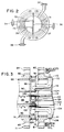
- Figure 2 is an end view of the reactor system of Figure 1.
- Figure 3 is a cross-sectional schematic view of a portion of a reactor system for use in the process of the present invention.
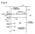
- Figure 4 is a schematic view of a portion of a reactor system for use in the process of the present invention.
- Figures 5a and 5b are schematic end views of a reactor system for use in the process of the present invention.
- Figures 6a and 6b are schematic end views of a reactor system for use in the process of the present invention.
- Figure 7 is a schematic view of a process according to the present invention.
- Figure 8 is a graph showing product distribution for a theoretical prior art process.
- Figure 9 is a graph showing product distribution for a process conducted according to the present invention.
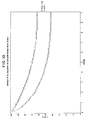
- Figure 10 is a graph comparing a prior art process and a process according to the present invention.
- Figure 11 is a cross-sectional view of a gas sparger used in reactors for use in the process of the present invention.
- Tables I and II present data from a run of a single tube reactor according to the present invention.
- Table III presents data from a process according to the present invention.
- Table IV presents data from a process according to the present invention.
- a reactor system 10 for use in the process of the present invention has a shell section 12, a head 56 on a left end 14, and a head 58 on a right end 16.
- the shell section 12 (made e.g. from carbon steel) has a variety of inlets and outlets including: reactant entry nozzle 68; heat transfer medium inlet nozzles 18 and 20; drains 22 and 24 a relief outlet 26; instrument access nozzles 28 and 30; ethylene feed inlets for the head 56; inlets 32, 34, 36 and 38; ethylene feed inlets for the head 58; 42, 44, 46 and 48; a product discharge outlet 40; and a tube side relief outlet 70; and a heat transfer medium outlet 54.
- a primary tube sheet 50 is disposed between the shell section 12 and the head 56.
- Tube sheet 50 is made from Hastelloy B-2TM material or a multi-layer member made from layers of carbons teel, nickel, and Hastelloy B-2 explosion bonded or welded together; e.g. 5/8 inch (16 mm) Hastelloy B-2, 1/8 inch (3.2 mm) nickel, and 7 to 9 inch (180 to 230 mm) of carbon steel.
- a primary tube sheet 52 is disposed between the shell section 12 and the head 58. End plates close off each head. An end plate 60 with a sealing gasket 64 is secured to the head 56. An end plate 62 with a sealing gasket 66 is secured to the head 58. It is preferred that whatever in the reactor encounters the reactants is made from Hastelloy B-2 material.
- each ethylene feed inlet 32, 34, 36, 38 feeds into a particular section of the reactor system 10.
- the reactor system 10 has eight sets of transverse reaction tubes (not shown). Each set of tubes is fed by an individual ethylene feed; hence there are eight such inlets 32, 34, 36, 38 and 42, 44, 46, 48.
- ethylene is fed into the tubes by feeding ethylene into a chamber and from it into spargers extending into each reaction tube from the chamber.
- Ethylene and other reactants (benzene and catalyst complex) move through the tubes, reacting and producing heat and reaction products.
- the tubes end in another liquid chamber from which extends another set of reaction tubes.
- Ethylene is again injected by spargers into the beginning of the new set of reaction tubes and the added ethylene, reactants, and products move back in the other direction through the shell section with the reaction proceeding as the materials move through the tubes.
- the materials make eight passes through the shell section; hence there are eight ethylene feeds.
- Ethylene feed inlet 38 at a first end of the reactor as shown in Figure 2 feeds ethylene into an ethylene chamber 39 from which it is fed via spargers (not shown) to a first set or pass of reaction tubes (not shown) containing benzene and catalyst complex. After these materials move across the shell section 12 in the first pass through the first set of reaction tubes, additional ethylene is injected via ethylene feed inlet 48 at the other end (a second end) of the reactor which feeds into another ethylene chamber (not shown). From this chamber ethylene flows through spargers (not shown) into the second set or pass of reaction tubes (not shown) which extend to and intercommunicate with liquid chamber 37 ( Figure 2).
- ethylene feed inlet nozzle 36 Via ethylene feed inlet nozzle 36, additional ethylene is injected into a third set of reaction tubes which extend from chamber 37 to the second end of the reactor to another chamber (not shown).
- a fourth set of reaction tubes extending from this chamber are fed with ethylene from ethylene feed inlet nozzle 46 (via spargers) and the tubes extend back to a chamber 33.
- a fifth set of reaction tubes (not shown) extending from the chamber 33 are fed with ethylene from an ethylene feed inlet nozzle 34, the ethylene entering the tubes through spargers (not shown). These tubes (the fifth set) extend to a chamber (not shown) at the second end, of the reactor.
- the next set of tubes (the sixth set) extending from this chamber are fed with ethylene from ethylene feed inlet nozzle 44 (via spargers).
- These tubes extend to the first end of the reactor and end in a chamber 31. Additional ethylene is injected into spargers (not shown) disposed in a seventh set of reaction tubes (not shown) via ethylene feed inlet nozzle 32 and spargers (not shown).
- the seventh set of reaction tubes extend from the chamber 31 in the first end of the reactor to another chamber (not shown) from which the eighth and final set of reaction tubes extends.
- Ethylene is fed via an ethylene feed nozzle 42 through spargers (not shown) into the final (eighth) set of reaction tubes.
- the eighth set of reaction tubes extend from the chamber adjacent ethylene feed nozzle 42 in the second end of the reactor to a chamber 35 ( Figure 2) from which products of the reaction exit the reactor via product outlet 40.
- FIG. 3 Shown schematically in Figure 3 is a four-pass reactor system 71 (10 in Figure 1) for use in the process of the present invention having four sets or passes of reaction tubes, with tubes 112, 126, 114, 116 (shown).
- a head 76 (56 in Figure 1) is secured to a shell section 72 (12 in Figure 1) by securing a flange 78 of the shell section 72 (12 in Figure 1) to a flange 82 of the head 76 (56 in Figure 1) by bolts (not shown) extending through bolt holes 84, 85 (in flange 82) and bolt holes 80, 81 (in flange 78).
- a secondary tube sheet 86, a gas chamber channel wall 88, and gas chamber inner walls 90 and 98 (made e.g. from Hastelloy B-2 alloy and welded together) define two ethylene gas chambers 94 and 96 each fed by and ethylene feed nozzle (not shown, like feed 32-38, 42-48). Ethylene is conveyed from the ethylene gas chambers 94 and 96 by sparger feed tubes 100 and 102, respectively, which extend into reaction tubes 114 and 112, respectively.
- the secondary tube sheet 86 is spaced apart from a primary tube sheet 74 (50 in Figure 1) by a benzene chamber channel wall 124 which (with extensions of the gas chamber inner walls 90 and 98 extending through the secondary tube sheet 86 to contact the primary tube sheet 74) define reactant entry chambers 118 and liquid chambers 120 and 122.
- Reactants e.g. liquid benzene and a catalyst complex
- Reactants flow through a reactant inlet nozzle 108 (68 in Figure 1) extending through the shell section 72 (12 in Figure 1) and through the primary tube sheet 74 (50 in Figure 1), into the reactant entry chamber 118 at a first end of the shell section 72 (12 in Figure 1). From this chamber 118, the reactants flow into the reaction tube 112 in which they turbulently encounter ethylene gas fed into the reaction tube 112 through the sparger feed tube 102.
- reaction tube 112 then flow turbulently through the reaction tube 112 to the other end (a second end not shown) of the shell section 72 (12 in Figure 1), ending in another reactant entry chamber (not shown) from which another reaction tube 126 extends back to the head 76 (56 in Figure 1) in the first end of the shell section.
- additional ethylene is injected into reaction tube 126 and the reactants then flow through reaction tube 126 to the liquid chamber 120.
- the reactions proceed with materials moving from the chamber 120; into and through reaction tube 114; into another chamber (not shown) at the other end of the shell section; into reaction tube 116; into chamber 122; and out through product outlet nozzle 110 (40 in Figure 1).
- ethylene from an ethylene chamber 94 is injected into reaction tube 114.
- ethylene is sparged into the reaction tube 116.
- Figure 3 a schematic drawing, a plurality of reaction tubes can extend from each of the chambers 118, 120 and 122.
- the reaction tubes within shell section 72 (12 in Figure 1) are surrounded by a heat transfer medium 104 (e.g. but not limited to liquid polyethylated benzene or water to which is transferred the heat of the ethylene-benzene reaction.
- a heat transfer medium 104 e.g. but not limited to liquid polyethylated benzene or water to which is transferred the heat of the ethylene-benzene reaction.
- the heat transfer medium Via heat transfer medium inlet and outlet nozzles (not shown; like nozzles 18, 20 and 54 in Figure 1) the heat transfer medium circulates due to a thermosiphon effect or by the action of a conventional pump and thus the heat exchange medium 104 is moved through the shell section 72 (12 in Figure 1).
- the heat is extractable and can be used, e.g. to heat a stream in the process; to provide heat for, the distillation of the various products present in the product stream flowing from the outlet nozzle 110 (40 in Figure 1); or to generate steam for other uses.
- a reactor system 131 may employ sparger tubes 132 and 134 that extend into reaction tubes 142 and 144 that are flush with, but do not extend beyond, a primary tube sheet 136 (52 in Figure 1).
- the spargers extend from a secondary tube sheet 130 on the other side of which (right side in Figure 4) is an ethylene gas chamber 147 like, e.g. the chamber 96 in the reactor system 71 shown in Figure 3.
- the sparger tubes 132 and 134 extend across a liquid reactant chamber 146 from which reactants flow into the reaction tubes 142 and 144.
- pressure drop P1 there are three pressure drops in an apparatus such as the reactor system 131 which affect material distribution - the pressure drop P1 from the liquid chamber 146 to the interior of the reactor tubes 142 and 144; the pressure drop P2 across the liquid chamber 146, i.e. the pressure drop across the spargers 132 and 134; and the ethylene pressure drop P3 at the exit holes 133 and 135 in the ethylene spargers.
- pressure drop P1 should be significantly greater than pressure drop P2.
- the opening of the reactor tube 142 should experience liquid pressure at almost the same pressure as the pressure of liquid at the opening to the reactor tube 144.
- the pressure of the liquid at the opening to the reaction tube 144 should not be significantly less than 370 p.s.i. (2500 kPa). It is preferred that it be at least about 369.7 p.s.i. (2500 kPa).
- the pressure drop P3 at the holes 133 and 135 in the ethylene spargers 134 and 132, respectively, should be significantly greater than a pressure drop P4 across the ethylene chamber 147. In other words, the effect of ethylene existing sparger 134 should not be so great that it significantly reduces the pressure of ethylene pressure experienced at the opening to the sparger 132. Liquid flows into the chamber 146 through reaction tubes 138, 140.
- Figures 5a, 5b, 6a and 6b show two different chamber arrangements for reactors for use in the process of the present invention.
- Figures 5a and 5b show a "ribbon" chamber arrangement in which ethylene gas chambers and reactant chambers extend from one side of the head to the other; a plurality of reaction tubes intercommunicate with the reactant chambers and a plurality of sparger tubes extend across the reactant (liquid) chambers.
- Figures 6a and 6b show a "quadrant" chamber arrangement (as in Figure 2).
- the chamber arrangement refers to the way in which partitions (made e.g. from Hastelloy B-2 material) in the heads are oriented, and consequently affects the liquid flow geometry through the heads.
- a ribbon chamber arrangement ( Figures 5a, 5b) is superior to a quadrant chamber arrangement ( Figures 6a, 6b) for two reasons. Both reasons are related to the inherent lower liquid chamber crossflow velocities in the ribbon layout relative to that in the quadrant layout.
- Lower crossflow velocities reduce or prevent vibration of the unsupported spargers which extend into the head.
- Second, lower crossflow velocities result in a lower liquid chamber crossflow pressure drop (P2).
- P2 liquid chamber crossflow pressure drop
- a lower crossflow pressure drop results in improved liquid flow distribution to the reaction tubes, resulting in improved yields.
- the advantages of the chamber arrangement become more significant as the scale of the reactor increases.
- each section of a reactor shell 160 represents a reactant entry chamber 162 (like chamber 118, Figure 3); liquid chambers 164a-g (like chamber 120, Figure 3); or a chamber 166 from which product exits (like chamber 122, Figure 3).
- Eight reaction passes of reactants take place in the shell 160; i.e. passes between sections:
- reaction tubes are arranged as the tubes 168 and 169 shown in section 164c.
- Reactants enter section 164c (a liquid chamber) through the reaction tubes 168 and leaves the section through the tubes 169.
- the height of section 164c is H and the reactants from the tubes 168 must traverse the majority of the height H to enter the tubes 169.
- a reactor shell 180 is also divided into chambers or sections, a reactant entry chamber 182; liquid chambers 184a-g; and a product exit chamber 186.
- a reactant entry chamber 182 As shown in Figures 6a and 6b, a quadrant arrangement, a reactor shell 180 is also divided into chambers or sections, a reactant entry chamber 182; liquid chambers 184a-g; and a product exit chamber 186.
- a product exit chamber 186 there are eight reaction passes:
- the liquid chamber width is defined as the inside distance between the primary and secondary tube sheets (e.g. between sheets 74 and 86 in Figure 3).
- the liquid chamber width is critical to achieving uniform liquid flow distribution among all tubes of a given pass.
- One key to improving uniform liquid flow distribution is to increase the ratio of the pressure drop of the liquid entering the tubes to the pressure drop of the liquid flowing across the extended gas spargers. It is preferred that this pressure drop ratio, e.g., P1/P2 discussed in relation to the system of Figure 4 be greater than 10, but most preferably equal to or greater than 25 to reduce liquid maldistribution to less than 15 percent and most preferably less than 3.5 percent.
- liquid chamber width should be at least 4" (102 mm) (resulting in a pressure drop ratio of 20) to reduce liquid maldistribution to less than 3.5 percent. Because the pressure drop ratio is not a function of total liquid flowrate, liquid flow, distribution and the choice of a suitable liquid chamber width are not affected by reactor capacity.
- Pitch ratio and layout refers to the disposition of and spacing between reaction tubes. Reaction tubes in a triangular layout result in a higher heat transfer coefficient than tubes in a square layout, and also require a smaller diameter shell for a given number of tubes. In a squared layout one tube may mask flow to or around another tube. It is preferred that tubes be offset from each other. "Pitch” is the distance between two tubes. “Pitch ratio” is the ratio of pitch to the outside diameter of the tubes.
- a “30° layout” refers to equiangularly spaced tubes in a generally triangular array; i.e. connecting three adjacent tubes from a triangle with one tube at the top and two on the base, a line drawn from the top tube to the base bisects the top angle of the triangle, i.e. forming two 30° angles.
- the ethylene sparger tube outer diameter is critical to achieving uniform liquid flow distribution among all tubes of a given pass.
- the pressure drop of the liquid entering a reaction tube increases.
- the ratio of this pressure drop to the pressure drop of the liquid flowing across the extended gas spargers increases, and liquid flow distribution improves.
- the overall pressure drop through the reactor increases as well as P1.
- a sparger tube outer diameter of at least 3/8" (9.5 mm) reduces liquid maldistribution to less than 3.5 percent. It is preferred that this diameter in combination with other design factor be such that, e.g. in the system of Figure 4, P1 be significantly greater than P2, i.e. greater than 10 and preferably greater than 25.
- the sparger hole is the opening at the end of the sparger tube through which gas (or liquid in other processes) flows into the reaction tube (e.g. holes 133, 135, Figure 4).
- the sparger hole size is critical to achieving uniform gas flow distribution among all tubes of a given pass. As the sparger hole diameter decreases, gas flow distribution improves. For a total ethylene feedrate of 54,000 lb/hr (20,000 kg/hr) and the reactor configuration described previously, a sparger hole diameter of 0.0625" (1.6 mm) limits gas flow maldistribution to less than 2 percent. It is preferred that sparger hole size be adjusted so that gas flow maldistribution is at least less than 15 percent.
- the reactor configuration parameters of tube diameter, tube length, number of passes, and number of tubes per pass can be optimized simultaneously.
- Four criteria considered in optimizing preferred embodiments of this invention are: minimizing residence time in the reactor; maintaining a recommended heat transfer flux across the tubes and maximizing heat recovery; and ensuring maximum or complete reaction of ethylene.
- Ethylene feedrate 54,000 pounds/hour (20,000 kg/hr)
- Benzene feedrate 400,000 pounds/hour (182,000 kg/hr)
- Ethylene inlet temperature 50°C
- Benzene inlet temperature 220°C
- Reactor pressure at inlet 395 psia (2720 kPa)
- Shellside boiling temperature (vaporization begins ) 208°C
- Shellside exit vapor fraction (% vapor of exiting heat transfer medium) 0.200
- optimum values for tube length and number of tubes per pass are 23 feet (7 m) and 500, respectively.
- Tube diameter is held to a minimum of 0.75" (19 mm) O.D., and the number of passes was held at a maximum of 8.
- a preferred heat transfer flux is between 2000 and 8000 Btu/hour/square foot of heat transfer surface area. For this embodiment it is about 4000 Btu/hr/ft2.
- the sparger tube penetration length is defined as the axial distance that an ethylene sparger protrudes down into the start of a reaction tube.
- the sparger tube penetration length should be no less than .5 inches (12.7 mm) to ensure that no ethylene backs out of a reaction tube.
- the sparger tube penetration length accounts for only about 10 percent of the total pressure drop of the liquid tube-entry pressure drop, and so plays only a minor role in determining liquid flow distribution and total pressure drop through the reactor.
- an ethylene gas sparger 400 made from a piece of Hastelloy B-2 material tubing, has a nozzle end 402 which is swaged down so that a hole 404 of desired size provides an exit opening for ethylene gas to flow into a reaction tube.
- the sparger 400 is shown as welded to a tube sheet 406 of a thickness B.
- the sparger's overall length is A, the length of the nozzle end is D, the sparger tube outer diameter is F, side wall thickness is G, the hole opening size is E, and the sparger extends to a length C beyond the tube sheet for ease of welding.
- these dimensions are:
- FIG 7 illustrates schematically a process 300 for producing ethylbenzene according to the present invention.
- catalyst about 400 pounds per hour (181 g/hr), 25°C
- aluminum chloride - HCl catalyst for this reaction is fed into an end head (not shown; like head 56, Figure 1 or head 76, Figure 3) of a reactor 303 via a feed line 302.
- ethylene gas at about 25°C is fed into the head of the reactor 303.
- Via a feed line 304 benzene at about 220°C is fed into the reactor 303. It is preferred that an excess of benzene, at least 100 percent, but preferably 200 percent or more, (e.g. 3 molecules of benzene for each molecule of ethylene) be fed to the reactor.
- the reactor 303 is like the previously described reactors.
- Reaction products and other materials exit from the reactor 303 via line 305 at about 230°C.
- a valve 306 in line 305 controls the pressure in the reactor 303 (set, e.g. at about 350 p.s.i.g. (2400 kPa gauge)).
- the materials in line 305 are relatively hot (230°C in this example) and they are fed through a heat exchanger 307 in heat transfer relationship with benzene at 90°C from a line 308. This benzene is heated from 90°C to 220°C (line 304).
- the reaction products and materials (now cooled to 145°C) flow from the heat exchanger 307 in line 309.
- this stream then flows to a heat exchanger 340 wherein heat is transferred from the materials in line 309 to a stream 323 (primarily benzene) from a benzene recovery tower 322.
- the materials from line 309 exit the heat exchanger in line 341 at about 125°C.
- the materials in line 341 Prior to joining materials in line 310, the materials in line 341 are cooled by a cooler (e.g. fan) 342 to about 65°C.
- the reaction products and other materials in line 341 mix with polyethylated benzenes recovered by a tower 311 and flow through line 312 to a transalkylation reactor 313.
- the transalkylation reactor 313 is operated at 65°C. It produces a product in line 314 in which the amount of polyethylated benzenes from line 312 have been reduced and the amount of ethylbenzenes has been increased.
- Line 314 also contains unreacted catalyst.
- the materials in line 314 are fed to a catalyst settler 315 run at, 3 e.g., 50°C, wherein recyclable catalyst which can be fed back to the transalkylation reactor 313 via a line 316 (at 50°C); and a materials stream which exits the settler 315 via a line 317 are produced.
- Line 317 contains ethylbenzene, benzene, polyethylated benzenes, and catalyst. It is fed to a wash system into which water is fed via a line 319 and from which water and dead catalyst exit via a line 320.
- the materials exiting from the wash system 318 flow via a line 321 (at 50°C) to the benzene recovery tower 322.
- the material stream in line 321 is, e.g., about 53 percent benzene, about 40 percent ethylbenzene, and about 7 percent polyethylated benzenes.
- Benzene exits from the top of this distillation tower and flows via a line 323 to a benzene drying tower 324.
- the materials remaining from line 321 (ethylbenzene and polyethylated benzenes) flow via a line 325 at 124°C to an ethylbenzene finishing distillation tower 326.
- Ethylbenzene at 150°C exits from the top of the tower 326 via a line 327.
- Polyethylated benzenes exit the tower 326 via a line 329. A portion of them (e.g. about 1 percent) flow via a line 330 to the polyethylated benzenes recovery distillation tower 311. Another portion of the polyethylated benzenes at 208°C are flowed via a line 328 to act as the heat transfer medium in the reactor 303 ("EB TOWER BOTTOMS"). These polyethylated benzenes are heated in the reactor 303 by the exotherm from the ethylene - benzene reaction in the reactor's reaction tubes.
- the heated polyethylated benzenes at, e.g., about 210°C flow from the reactor 303 via a line 331 back to the ethylbenzene finishing tower 326 to provide heat energy for the tower 326.
- the EB TOWER BOTTOMS in line 328 are essentially 100 percent liquid.
- a vapor/liquid combination exits the reactor 303 via line 331 and it is preferred that it be 5 percent to 50 percent vapor, most preferably about 15 percent vapor and about 85 percent liquid.
- the reaction products and other materials in line 312 may be present as follows (percent by weight): 60 percent benzene; 30 percent ethyl benzene; 10 percent polyethylated benzenes; negligible amount of catalyst.
- the benzene content might range as low as 30 percent; the ethylbenzenes as low as 5 percent and as high as 45 percent; and the polyethylbenzenes as high as 30 percent.
- the stream in line 314 is preferably: about 53 percent benzene: about 40 percent ethylbenzene; and about 7 percent polyethylated benzenes - all ranging as dependent on the ranges stated regarding line 312.
- polyethylated benzenes recovery tower 311 From the polyethylated benzenes recovery tower 311 polyethylated benzenes exit via a line 310 and proceed to join with the products from the reactor 303 (in line 309) to flow to the transalkylation reactor 313.
- a condenser 343 cools the materials in line 310.
- Tar (residue) flows from the tower 311 via a line 332.
- the graphs in Figures 8, 9, and 10 present a theoretical comparison of a prior art process in which polyethylated benzenes are recycled to an alkylator reactor and a process according to the present invention in which produced polyethylated benzenes are not recycled to the alkylator reactor (as they are e.g. in feed line 310 to reactor 313 in Figure 7).
- the abscissa of these graphs, epsilon represents the process' ratio of ethylene to benzene in the reactor feed; e.g. .333 would indicate 1 molecule of ethylene per 3 molecules of benzene.
- the graph of Figure 10 illustrates a comparison of the conversion of ethylene and benzene to ethylbenzene in a prior art process employing a larger reactor for both alkylation and transalkylation and a process according to the present invention employing a reactor according to the present invention as previously described.
- the "S" line is for a CSTR, a prior art continuous stirred tank reactor in which back mixing occurs; i.e. the undesirable formation of polyethylbenzenes occurring when ethylbenzenes and previously-formed polyethylbenzenes are recirculated in the tank reactor to again react with ethylene to form more polyethylbenzenes. Reaction times in such a reactor are typically 45 to 60 minutes.
- the total residence time in the reactor would be about 1 minute, or slightly less than 8 seconds (7.5 seconds) per pass. It is preferred that residence times be 15 seconds or less.
- This process is represented as the "P" line in Figure 10 since it approaches plug-flow. As shown the conversion to ethylbenzene is significantly higher for the process (P) according to the present invention.
- the vertical axis in Figure 10 represents percent approach to equilibrium (equilibrium is the point at which no further reaction occurs).
- Tables I and II present data obtained from a run of a single tube ("showtube") unit described to indicate performance of ethylene injection, reaction, and heat transfer according to the present invention.
- the reactor for this unit was a 13.5 foot by 1.5 inch Hastelloy alloy pipe jacketed with a 2.5" (63.55 mm) diameter carbon steel pipe.
- Catalyst used for this run was a "red oil" complex prepared from aluminum metal, HCl gas and liquid ethylated benzenes.
- the catalyst composition is prepared in a separate vessel as follows: aluminum metal (solid) fed at 5 weight percent; liquid polyethylbenzene fed at 57 weight percent; HCl gas fed at 38 weight percent; fed at 75°C and 30 p.s.i.g.
- the reaction temperature approaced 205°C at a distance of about 46 inches (1170 mm) into the tube and stayed between 205°C and 210°C until about 138 inches (3500 mm) into the tube.
- the heat transfer medium in the shell (jacket) approached 150°C 32 inches (813 mm) into the shell and remained around 155°C to 160°C. This fairly consistent temperature profile along the tube indicated that such a tube and such materials under these conditions would efficiently transfer heat from the reaction in the tube to the heat transfer material, heat which could then be utilized elsewhere in the process.
- Table III presents data for a process to produce ethylbenzene in accordance with the present invention in a reactor system as illustrated in Figures 1, 2 and 6a.
- flow parameters are as follows: Shell Internal Temperature (heat transfer medium) 207°C Benzene Feed Temperature 225°C Benzene Feed Pressure 357.5 psig (2465 kPa gauge) Product Outlet Pressure 348.2 psig (2400 kPa gauge) Shell Pressure 7.08 psig (49 kPa gauge) Total Ethylene Feed Rate 571 pounds/hour (259 kg/hr) Benzene Feed Rate 4495 pounds/hour (2040 kg/hr) Catalyst Feed Rate 8.88 pounds/hour (4 kg/hr) HCl (gas) Feed rate 11.08 pounds/hour (5 kg/hr)
- the flow of ethylene in pounds per hour (kg/hr) to each of these chambers is as follows:
- the exit temperature (in degrees Celsius) of reactant materials and products for each pass (temperature measured at the end of each pass in the liquid chambers) is as follows:
- the heat transfer coefficient for this process is 197 Btu/hour/ft2/°F (1119 W/(m2 ⁇ k)).
- Table III as well as the data above indicate: (a) essentially all ethylene is reacted in each pass: (b) the temperature profile of the reactants is relatively flat which shows that the heat of the reaction is being uniformly and efficiently transferred to the heat transfer medium; (c) a uniform amount of ethylene is being fed to each of the eight passes; and (d) the epsilon in the alkylator is approximately 0.35, i.e., about one ethyl group per each three aromatic rings.
- Table IV presents data from a process according to the present invention in a reactor system as illustrated in Figures 5a and 7.
- flow parameters are as follows: Shell Internal Temperature 216.6°C Ethylene Feed Temperature 21.6°C Benzene Feed Temperature 230.8°C Benzene Feed Pressure 391.7 psig (2700 kPa gauge) Shell Pressure 28.3 psig (195 kPa gauge) Benzene Feed Rate 353,100 pounds/hour (160,166 kg/hr) Catalyst Feed Rate 2799 pounds/hour (1270 kg/hr) HCl (gas) Feed Rate 82.9 pounds/hour (38 kg/hr) Total Ethylene Feed Rate 49,910 pounds/hour (22600 kg/hr) Heat Transfer Coefficient Btu/Hour/Ft2/°F (W/m2 ⁇ k) 160 (900) AlCl3 concentration (ppm) 1805 Liquid temperatures (°C) for each pass of reactant materials are:
- the alkylation and transalkylation steps are carried out separately and thus each step can be individually optimized.
- the alkylation process can be optimized to reduce or negate the effects of back mixing which occur even in prior art processes in which transalkylation and alkylation are carried out in two separate reactors.
- the catalyst concentration exceeds the solubility limit of catalyst in the liquid reactants producing a heterogeneous reaction mixture which contains two liquid phases (and therefore requires more catalyst). Two liquid phases moving down reaction tubes would perform inefficiently.
- Catalyst concentrations in preferred processes according to the present invention e.g.
- Yields for processes and alkylators according to this invention are very high. For example, in a process carried out in a reactor such as that of Figures 1 and 2 and alkylator, yield of 99,7 percent (which would correspond to an overall plant yield of 99,6 percent) was achieved.
Landscapes
- Chemical & Material Sciences (AREA)
- Organic Chemistry (AREA)
- Engineering & Computer Science (AREA)
- Chemical Kinetics & Catalysis (AREA)
- Physics & Mathematics (AREA)
- Thermal Sciences (AREA)
- Mechanical Engineering (AREA)
- General Engineering & Computer Science (AREA)
- Organic Low-Molecular-Weight Compounds And Preparation Thereof (AREA)
- Looms (AREA)
- Treatment Of Fiber Materials (AREA)
Applications Claiming Priority (3)
| Application Number | Priority Date | Filing Date | Title |
|---|---|---|---|
| US511489 | 1990-04-17 | ||
| US07/511,489 US5227556A (en) | 1990-04-17 | 1990-04-17 | Turbulent flow process, monoalkyl aromatic production process and reactor for such process |
| EP91909102A EP0477358B1 (de) | 1990-04-17 | 1991-04-12 | Wirbelstromverfahren sowie herstellung von monoalkylaromaten |
Related Parent Applications (2)
| Application Number | Title | Priority Date | Filing Date |
|---|---|---|---|
| EP91909102A Division EP0477358B1 (de) | 1990-04-17 | 1991-04-12 | Wirbelstromverfahren sowie herstellung von monoalkylaromaten |
| EP91909102.5 Division | 1991-04-12 |
Publications (2)
| Publication Number | Publication Date |
|---|---|
| EP0703202A1 true EP0703202A1 (de) | 1996-03-27 |
| EP0703202B1 EP0703202B1 (de) | 1999-11-03 |
Family
ID=24035126
Family Applications (2)
| Application Number | Title | Priority Date | Filing Date |
|---|---|---|---|
| EP95203075A Expired - Lifetime EP0703202B1 (de) | 1990-04-17 | 1991-04-12 | Verfahren zur Herstellung von Ethylbenzol |
| EP91909102A Expired - Lifetime EP0477358B1 (de) | 1990-04-17 | 1991-04-12 | Wirbelstromverfahren sowie herstellung von monoalkylaromaten |
Family Applications After (1)
| Application Number | Title | Priority Date | Filing Date |
|---|---|---|---|
| EP91909102A Expired - Lifetime EP0477358B1 (de) | 1990-04-17 | 1991-04-12 | Wirbelstromverfahren sowie herstellung von monoalkylaromaten |
Country Status (7)
| Country | Link |
|---|---|
| US (2) | US5227556A (de) |
| EP (2) | EP0703202B1 (de) |
| JP (1) | JP3080403B2 (de) |
| CA (1) | CA2058430A1 (de) |
| DE (2) | DE69121033T2 (de) |
| ES (1) | ES2090330T3 (de) |
| WO (1) | WO1991016285A1 (de) |
Families Citing this family (9)
| Publication number | Priority date | Publication date | Assignee | Title |
|---|---|---|---|---|
| BE1006377A3 (fr) * | 1992-11-24 | 1994-08-09 | Raffinerie Tirlemontoise Sa | Procede de separation d'une composition polydispersee de saccharides, produits obtenus par ce procede et utilisation des produits obtenus dans des compositions alimentaires. |
| US5443799A (en) * | 1993-08-03 | 1995-08-22 | Orgral International Technologies Corporation | Process for the alkylation of olefins and apparatus for carrying out this process and others |
| US5676911A (en) * | 1995-12-14 | 1997-10-14 | Her Majesty The Queen In Right Of Canada, As Represented By The Minister Of National Defence Of Her Majesty's Canadian Government | Radial flow fuel processor |
| US5977422A (en) * | 1997-06-09 | 1999-11-02 | The Dow Chemical Company | Organoaluminum catalysis of alkylation reactions |
| TW527218B (en) * | 1999-03-16 | 2003-04-11 | Basf Ag | Multitube reactor, especially for catalytic gas-phase reactions |
| US7273221B2 (en) * | 2001-12-20 | 2007-09-25 | Transbike Systems, Inc. | Attachment system for bicycle accessories |
| US20050147980A1 (en) * | 2003-12-30 | 2005-07-07 | Intel Corporation | Nucleic acid sequencing by Raman monitoring of uptake of nucleotides during molecular replication |
| US7297827B2 (en) | 2004-11-29 | 2007-11-20 | Fina Technology, Inc. | Use of monolith catalyst to prepare ethylbenzene |
| CN104729323B (zh) * | 2013-12-23 | 2019-01-25 | 裴志中 | 内筒和漏斗分程式双壳程管壳式换热器 |
Citations (3)
| Publication number | Priority date | Publication date | Assignee | Title |
|---|---|---|---|---|
| GB589072A (en) * | 1941-08-01 | 1947-06-11 | Standard Oil Dev Co | An improved process for the production of ethyl benzene |
| US3848012A (en) * | 1973-09-26 | 1974-11-12 | Monsanto Co | Alkylation process |
| EP0190057A1 (de) * | 1985-01-31 | 1986-08-06 | The Dow Chemical Company | Verfahren zur Alkylierung von aromatischen Kohlenwasserstoffen |
Family Cites Families (34)
| Publication number | Priority date | Publication date | Assignee | Title |
|---|---|---|---|---|
| US2139943A (en) * | 1934-07-13 | 1938-12-13 | Pennsylvania Petroleum Res Cor | Process and apparatus for treating mineral oils |
| US2429622A (en) * | 1942-10-28 | 1947-10-28 | Foster Wheeler Corp | Catalytic production of ethyl benzene |
| US2491618A (en) * | 1943-07-30 | 1949-12-20 | Standard Oil Co | Catalytic contacting apparatus |
| US3121123A (en) * | 1961-03-20 | 1964-02-11 | California Research Corp | Preparation of primary normal alkyl benzenes |
| US3212860A (en) * | 1962-03-23 | 1965-10-19 | Phillips Petroleum Co | Method of and apparatus for contacting immiscible fluids |
| US3200164A (en) * | 1964-09-08 | 1965-08-10 | Universal Oil Prod Co | Alkylation-transalkylation process |
| US3448161A (en) * | 1968-02-12 | 1969-06-03 | Dow Chemical Co | Alkylation process |
| JPS5127637B1 (de) * | 1968-04-15 | 1976-08-13 | ||
| US3551510A (en) * | 1968-08-15 | 1970-12-29 | Universal Oil Prod Co | Alkylation-transalkylation process |
| US3501536A (en) * | 1969-02-26 | 1970-03-17 | Universal Oil Prod Co | Alkylation with spiralling flow path of reactants and alkylate |
| US3683043A (en) * | 1970-02-04 | 1972-08-08 | Marcello Ghirga | Method of preparing alkylbenzenes |
| US3817708A (en) * | 1970-02-25 | 1974-06-18 | Phillips Petroleum Co | Alkylation apparatus |
| US3696168A (en) * | 1970-09-21 | 1972-10-03 | Phillips Petroleum Co | Nozzle structure and arrangement for producing high octane alkylate |
| US3674885A (en) * | 1970-10-09 | 1972-07-04 | Atlantic Richfield Co | Alkylation of benzene utilizing fischer-tropsch olefin-paraffin mixtures |
| US3751232A (en) * | 1971-01-14 | 1973-08-07 | Universal Oil Prod Co | Means for effecting a multiple stage contact of a reactant stream |
| US3830864A (en) * | 1971-01-14 | 1974-08-20 | Universal Oil Prod Co | Process for effecting the multiplestage catalytic contact of a reactant stream |
| US3763022A (en) * | 1971-07-09 | 1973-10-02 | Phillips Petroleum Co | Condensing fractionator sidestream vapor as reboiler heat source |
| US3766290A (en) * | 1972-08-10 | 1973-10-16 | Dow Chemical Co | Process for the preparation of ethylbenzene |
| US3839548A (en) * | 1972-10-13 | 1974-10-01 | Lion Oil Co | Process for producing sodium hydrosulfide solutions |
| IT971361B (it) * | 1972-11-30 | 1974-04-30 | Sir Soc Italiana Resine Spa | Procedimento migliorato per la alchilazione |
| IT971360B (it) * | 1972-11-30 | 1974-04-30 | Sir Soc Italiana Resine Spa | Miglioramenti nei procedimenti di alchilazione |
| US3914110A (en) * | 1974-02-19 | 1975-10-21 | Universal Oil Prod Co | Alkylation reaction cooler |
| US3914111A (en) * | 1974-04-18 | 1975-10-21 | Universal Oil Prod Co | Alkylation reaction chamber |
| US4173615A (en) * | 1974-07-08 | 1979-11-06 | Mitsui Toatsu Chemicals, Incorporated | Chemical apparatus for corrosive materials |
| US4238462A (en) * | 1978-01-31 | 1980-12-09 | Air Resources, Inc. | Autocirculation process and apparatus |
| US4169111A (en) * | 1978-02-02 | 1979-09-25 | Union Oil Company Of California | Manufacture of ethylbenzene |
| US4221763A (en) * | 1978-08-29 | 1980-09-09 | Cities Service Company | Multi tube high pressure, high temperature reactor |
| US4179473A (en) * | 1978-10-10 | 1979-12-18 | The Lummus Company | Production of monoalkyl aromatics |
| FR2452315B1 (fr) * | 1979-03-28 | 1985-07-05 | Azote & Prod Chim | Reacteur de nitration d'hydrocarbures en phase gazeuse sous pression |
| GB2159431B (en) * | 1984-05-29 | 1988-04-27 | Shell Int Research | Reactor for non-isothermic reactions and process for the preparation of hydrocarbons using such a reactor |
| GB2177318B (en) * | 1985-07-02 | 1989-01-18 | Shell Int Research | Catalytic conversion of gas or liquid in a multitube reactor |
| DE3532413A1 (de) * | 1985-09-11 | 1987-03-12 | Uhde Gmbh | Vorrichtung zur erzeugung von synthesegas |
| JPH01252501A (ja) * | 1988-04-01 | 1989-10-09 | Agency Of Ind Science & Technol | 水素吸蔵合金反応容器 |
| US4995961A (en) * | 1988-08-19 | 1991-02-26 | Phillips Petroleum Company | Process and apparatus for hydrogenating hydrocarbons |
-
1990
- 1990-04-17 US US07/511,489 patent/US5227556A/en not_active Expired - Lifetime
-
1991
- 1991-04-12 WO PCT/US1991/002534 patent/WO1991016285A1/en active IP Right Grant
- 1991-04-12 DE DE69121033T patent/DE69121033T2/de not_active Expired - Fee Related
- 1991-04-12 DE DE69131769T patent/DE69131769T2/de not_active Expired - Fee Related
- 1991-04-12 JP JP03508813A patent/JP3080403B2/ja not_active Expired - Fee Related
- 1991-04-12 ES ES91909102T patent/ES2090330T3/es not_active Expired - Lifetime
- 1991-04-12 CA CA002058430A patent/CA2058430A1/en not_active Abandoned
- 1991-04-12 EP EP95203075A patent/EP0703202B1/de not_active Expired - Lifetime
- 1991-04-12 EP EP91909102A patent/EP0477358B1/de not_active Expired - Lifetime
-
1992
- 1992-12-17 US US07/992,204 patent/US5334357A/en not_active Expired - Lifetime
Patent Citations (3)
| Publication number | Priority date | Publication date | Assignee | Title |
|---|---|---|---|---|
| GB589072A (en) * | 1941-08-01 | 1947-06-11 | Standard Oil Dev Co | An improved process for the production of ethyl benzene |
| US3848012A (en) * | 1973-09-26 | 1974-11-12 | Monsanto Co | Alkylation process |
| EP0190057A1 (de) * | 1985-01-31 | 1986-08-06 | The Dow Chemical Company | Verfahren zur Alkylierung von aromatischen Kohlenwasserstoffen |
Non-Patent Citations (1)
| Title |
|---|
| PATENT ABSTRACTS OF JAPAN * |
Also Published As
| Publication number | Publication date |
|---|---|
| JP3080403B2 (ja) | 2000-08-28 |
| DE69131769T2 (de) | 2000-03-09 |
| DE69121033T2 (de) | 1997-01-09 |
| US5227556A (en) | 1993-07-13 |
| US5334357A (en) | 1994-08-02 |
| CA2058430A1 (en) | 1991-10-28 |
| DE69131769D1 (de) | 1999-12-09 |
| DE69121033D1 (de) | 1996-08-29 |
| EP0477358A1 (de) | 1992-04-01 |
| ES2090330T3 (es) | 1996-10-16 |
| WO1991016285A1 (en) | 1991-10-31 |
| JPH05500815A (ja) | 1993-02-18 |
| EP0703202B1 (de) | 1999-11-03 |
| EP0477358B1 (de) | 1996-07-24 |
Similar Documents
| Publication | Publication Date | Title |
|---|---|---|
| US4232179A (en) | Process for preparing ethene | |
| EP1666451B1 (de) | Verbessertes Verfahren chemischer Reaktionen des Cyanohydrins | |
| US9242919B2 (en) | Process to prepare olefins from aliphatic alcohols | |
| US10029966B2 (en) | Method and reaction equipment for preparing dimethyl ether and olefin from methanol | |
| EP0703202B1 (de) | Verfahren zur Herstellung von Ethylbenzol | |
| MXPA06008616A (es) | Procedimiento para la fosgenacion en fase gaseosa. | |
| US5336821A (en) | Alkylation process with reactor effluent heat recovery | |
| GB2127321A (en) | Radial flow series bed catalytic reactor | |
| US3501536A (en) | Alkylation with spiralling flow path of reactants and alkylate | |
| CN114505021B (zh) | 用于丁二烯液相氯化制备二氯丁烯的螺旋板式多段反应器及二氯丁烯制备 | |
| CN113292459A (zh) | 一种硝酸胍连续硝化方法 | |
| US7038065B2 (en) | Process for catalytically producing organic substances by partial oxidation | |
| CN113941163B (zh) | 低压降式乙苯蒸发器及苯乙烯脱氢反应系统中乙苯汽化的节能工艺 | |
| WO2017100493A1 (en) | Reactor system for use with an ionic liquid catalyst | |
| EP2723702B1 (de) | Wärmetauscher und zugehöriges verfahren | |
| US4731465A (en) | Process for producing nitrilotriacetonitrile | |
| CN112500269B (zh) | 一种cdol脱氢制备cdon混合物冷却的装置系统和方法 | |
| EP0102936B1 (de) | Kontinuierliches Verfahren zur Herstellung von Nitrilotriacetonitril | |
| CN113226536A (zh) | 板式换热器与放热反应器的结合使用 | |
| RU2241533C1 (ru) | Установка для жидкофазного одностадийного синтеза изопрена (варианты) | |
| JP2023550265A (ja) | 転化時の逆混合の低減によるメチルメタクリレートおよび/またはメタクリル酸の改良された製造方法 | |
| KR100539325B1 (ko) | 에너지 절감형 정류탑과 이를 이용한 중합시스템 | |
| CN117902986A (zh) | 1,6-己二醇氨化制1,6-己二胺的方法 | |
| KR850001401B1 (ko) | 아크릴산의 제조법 | |
| WO2024019731A1 (en) | Reactor effluent heat recovery system |
Legal Events
| Date | Code | Title | Description |
|---|---|---|---|
| PUAI | Public reference made under article 153(3) epc to a published international application that has entered the european phase |
Free format text: ORIGINAL CODE: 0009012 |
|
| 17P | Request for examination filed |
Effective date: 19951110 |
|
| AC | Divisional application: reference to earlier application |
Ref document number: 477358 Country of ref document: EP |
|
| AK | Designated contracting states |
Kind code of ref document: A1 Designated state(s): BE DE ES FR IT NL |
|
| 17Q | First examination report despatched |
Effective date: 19970602 |
|
| RAP3 | Party data changed (applicant data changed or rights of an application transferred) |
Owner name: THE DOW CHEMICAL COMPANY |
|
| GRAG | Despatch of communication of intention to grant |
Free format text: ORIGINAL CODE: EPIDOS AGRA |
|
| GRAG | Despatch of communication of intention to grant |
Free format text: ORIGINAL CODE: EPIDOS AGRA |
|
| GRAG | Despatch of communication of intention to grant |
Free format text: ORIGINAL CODE: EPIDOS AGRA |
|
| GRAH | Despatch of communication of intention to grant a patent |
Free format text: ORIGINAL CODE: EPIDOS IGRA |
|
| GRAH | Despatch of communication of intention to grant a patent |
Free format text: ORIGINAL CODE: EPIDOS IGRA |
|
| GRAA | (expected) grant |
Free format text: ORIGINAL CODE: 0009210 |
|
| AC | Divisional application: reference to earlier application |
Ref document number: 477358 Country of ref document: EP |
|
| AK | Designated contracting states |
Kind code of ref document: B1 Designated state(s): BE DE ES FR IT NL |
|
| REF | Corresponds to: |
Ref document number: 69131769 Country of ref document: DE Date of ref document: 19991209 |
|
| REG | Reference to a national code |
Ref country code: ES Ref legal event code: FG2A Ref document number: 2137446 Country of ref document: ES Kind code of ref document: T3 |
|
| ITF | It: translation for a ep patent filed |
Owner name: ING. A. GIAMBROCONO & C. S.R.L. |
|
| PGFP | Annual fee paid to national office [announced via postgrant information from national office to epo] |
Ref country code: FR Payment date: 20000211 Year of fee payment: 10 |
|
| ET | Fr: translation filed | ||
| PGFP | Annual fee paid to national office [announced via postgrant information from national office to epo] |
Ref country code: DE Payment date: 20000310 Year of fee payment: 10 |
|
| PGFP | Annual fee paid to national office [announced via postgrant information from national office to epo] |
Ref country code: NL Payment date: 20000314 Year of fee payment: 10 |
|
| PGFP | Annual fee paid to national office [announced via postgrant information from national office to epo] |
Ref country code: ES Payment date: 20000412 Year of fee payment: 10 |
|
| PGFP | Annual fee paid to national office [announced via postgrant information from national office to epo] |
Ref country code: BE Payment date: 20000504 Year of fee payment: 10 |
|
| PLBE | No opposition filed within time limit |
Free format text: ORIGINAL CODE: 0009261 |
|
| STAA | Information on the status of an ep patent application or granted ep patent |
Free format text: STATUS: NO OPPOSITION FILED WITHIN TIME LIMIT |
|
| 26N | No opposition filed | ||
| PG25 | Lapsed in a contracting state [announced via postgrant information from national office to epo] |
Ref country code: ES Free format text: LAPSE BECAUSE OF NON-PAYMENT OF DUE FEES Effective date: 20010414 |
|
| PG25 | Lapsed in a contracting state [announced via postgrant information from national office to epo] |
Ref country code: BE Free format text: LAPSE BECAUSE OF NON-PAYMENT OF DUE FEES Effective date: 20010430 |
|
| BERE | Be: lapsed |
Owner name: THE DOW CHEMICAL CY Effective date: 20010430 |
|
| PG25 | Lapsed in a contracting state [announced via postgrant information from national office to epo] |
Ref country code: NL Free format text: LAPSE BECAUSE OF NON-PAYMENT OF DUE FEES Effective date: 20011101 |
|
| NLV4 | Nl: lapsed or anulled due to non-payment of the annual fee |
Effective date: 20011101 |
|
| PG25 | Lapsed in a contracting state [announced via postgrant information from national office to epo] |
Ref country code: DE Free format text: LAPSE BECAUSE OF NON-PAYMENT OF DUE FEES Effective date: 20020201 |
|
| PG25 | Lapsed in a contracting state [announced via postgrant information from national office to epo] |
Ref country code: FR Free format text: LAPSE BECAUSE OF NON-PAYMENT OF DUE FEES Effective date: 20021231 |
|
| REG | Reference to a national code |
Ref country code: FR Ref legal event code: ST |
|
| REG | Reference to a national code |
Ref country code: ES Ref legal event code: FD2A Effective date: 20030203 |
|
| PG25 | Lapsed in a contracting state [announced via postgrant information from national office to epo] |
Ref country code: IT Free format text: LAPSE BECAUSE OF NON-PAYMENT OF DUE FEES Effective date: 20050412 |
|
| PG25 | Lapsed in a contracting state [announced via postgrant information from national office to epo] |
Ref country code: FR Free format text: LAPSE BECAUSE OF NON-PAYMENT OF DUE FEES Effective date: 20010430 |