EP0702748B1 - Rotorschaufel mit gekühlter integrierter platform - Google Patents
Rotorschaufel mit gekühlter integrierter platform Download PDFInfo
- Publication number
- EP0702748B1 EP0702748B1 EP94900616A EP94900616A EP0702748B1 EP 0702748 B1 EP0702748 B1 EP 0702748B1 EP 94900616 A EP94900616 A EP 94900616A EP 94900616 A EP94900616 A EP 94900616A EP 0702748 B1 EP0702748 B1 EP 0702748B1
- Authority
- EP
- European Patent Office
- Prior art keywords
- cooling hole
- cooling
- platform
- flow
- disposed
- Prior art date
- Legal status (The legal status is an assumption and is not a legal conclusion. Google has not performed a legal analysis and makes no representation as to the accuracy of the status listed.)
- Expired - Lifetime
Links
Images


Classifications
-
- F—MECHANICAL ENGINEERING; LIGHTING; HEATING; WEAPONS; BLASTING
- F01—MACHINES OR ENGINES IN GENERAL; ENGINE PLANTS IN GENERAL; STEAM ENGINES
- F01D—NON-POSITIVE DISPLACEMENT MACHINES OR ENGINES, e.g. STEAM TURBINES
- F01D5/00—Blades; Blade-carrying members; Heating, heat-insulating, cooling or antivibration means on the blades or the members
- F01D5/12—Blades
- F01D5/14—Form or construction
- F01D5/18—Hollow blades, i.e. blades with cooling or heating channels or cavities; Heating, heat-insulating or cooling means on blades
-
- F—MECHANICAL ENGINEERING; LIGHTING; HEATING; WEAPONS; BLASTING
- F01—MACHINES OR ENGINES IN GENERAL; ENGINE PLANTS IN GENERAL; STEAM ENGINES
- F01D—NON-POSITIVE DISPLACEMENT MACHINES OR ENGINES, e.g. STEAM TURBINES
- F01D5/00—Blades; Blade-carrying members; Heating, heat-insulating, cooling or antivibration means on the blades or the members
- F01D5/12—Blades
- F01D5/14—Form or construction
- F01D5/141—Shape, i.e. outer, aerodynamic form
- F01D5/145—Means for influencing boundary layers or secondary circulations
-
- F—MECHANICAL ENGINEERING; LIGHTING; HEATING; WEAPONS; BLASTING
- F05—INDEXING SCHEMES RELATING TO ENGINES OR PUMPS IN VARIOUS SUBCLASSES OF CLASSES F01-F04
- F05D—INDEXING SCHEME FOR ASPECTS RELATING TO NON-POSITIVE-DISPLACEMENT MACHINES OR ENGINES, GAS-TURBINES OR JET-PROPULSION PLANTS
- F05D2240/00—Components
- F05D2240/80—Platforms for stationary or moving blades
- F05D2240/81—Cooled platforms
-
- F—MECHANICAL ENGINEERING; LIGHTING; HEATING; WEAPONS; BLASTING
- F05—INDEXING SCHEMES RELATING TO ENGINES OR PUMPS IN VARIOUS SUBCLASSES OF CLASSES F01-F04
- F05D—INDEXING SCHEME FOR ASPECTS RELATING TO NON-POSITIVE-DISPLACEMENT MACHINES OR ENGINES, GAS-TURBINES OR JET-PROPULSION PLANTS
- F05D2260/00—Function
- F05D2260/20—Heat transfer, e.g. cooling
- F05D2260/202—Heat transfer, e.g. cooling by film cooling
Landscapes
- Engineering & Computer Science (AREA)
- Mechanical Engineering (AREA)
- General Engineering & Computer Science (AREA)
- Physics & Mathematics (AREA)
- Fluid Mechanics (AREA)
- Turbine Rotor Nozzle Sealing (AREA)
Claims (4)
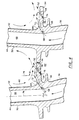
- Rotorlaufschaufel (28) für eine Axialströmungsgasturbinenmaschine (12), die um eine Längsachse herum angeordnet ist, wobei die Gasturbinenmaschine einen axial gerichteten Strömungsweg (22), der eine Passage für Arbeitsfluid definiert, eine Rotoranordnung (24), die eine Rotorscheibe (26) und die Rotorlaufschaufel (28) aufweist, und eine Quelle für Kühlfluid aufweist, wobei die Rotorlaufschaufel (28) einen Strömungsprofilbereich (32), der sich durch den Strömungsweg (22) erstreckt, eine Druckfläche (42) und eine Sogfläche (44) aufweist und einen hohlen Kern hat, einen Wurzelbereich (36), der radial innerhalb des Strömungsprofilbereichs (32) angeordnet ist und mit der Scheibe (26) zum Befestigen der Laufschaufel (28) an der Scheibe (26) zusammenwirkt, wobei der Wurzelbereich (36) einen Kernweg aufweist, der einen Strömungsweg für Kühlfluid definiert und sich mit der Quelle von Kühlfluid und mit dein hohlen Kern des Strömungsprofilbereichs (32) in Strömungsverbindung befindet, und eine Plattform (34) aufweist, die sich seitlich von der Laufschaufel (28) erstreckt und radial zwischen dem Strömungsprofilbereich (32) und dem Wurzelbereich (36) angeordnet ist, wobei die Plattform (34) eine äußere Oberfläche (52), die eine Strömungsoberfläche für den Strömungsweg (22) definiert, eine erste Ausrundung (64), welche die äußere Oberfläche (52) an den Strömungsprofilbereich (32) anschließt, eine innere Oberfläche (54), die zum Teil einen Unter-Plattform-Hohlraum (62) definiert, und eine zweite Ausrundung (66) aufweist, welche die innere Oberfläche (54) an den Wurzelbereich (36) anschließt, wobei die Rotorlaufschaufel (28) gekennzeichnet ist durcheine erste Kühlöffnung (56), die sich zwischen dem Kernweg und der äußeren Oberfläche (52) erstreckt, wobei die erste Kühlöffnung (56) radial innerhalb der ersten Ausrundung (64) und radial außerhalb der zweiten Ausrundung (66) angeordnet ist und einen Einlaß (68), der in dem Kernweg angeordnet ist, und einen Auslaß (72), der in der äußeren Oberfläche (52) und seitlich außerhalb der ersten Ausrundung (64) angeordnet ist hat, undeine zweite Kühlöffnung (58), die sich zwischen dem Unter-Plattform-Hohlraum (62) und der äußeren Oberfläche (52) erstreckt, wobei die zweite Kühlöffnung (58) einen Einlaß (76), der an der inneren Oberfläche (54) angeordnet ist, und einen Auslaß (78), der an der äußeren Oberfläche (52) angeordnet ist, aufweist, wobei der Auslaß (78) der zweiten Kühlöffnung seitlich außerhalb des Auslasses (72) der ersten Kühlöffnung angeordnet ist.
- Rotorlaufschaufel (28) nach Anspruch 1, wobei die Rotoranordnung (24) eine Mehrzahl von Rotorlaufschaufeln (28) aufweist, die umfangsmäßig um die Scheibe (26) beabstandet sind, wobei der Abstand derart ist, daß zwischen benachbarten Laufschaufeln (28) ein Zwischenschaufel-Wirbel (82) erzeugt wird, wobei der Zwischenschaufel-Wirbel (82) eine axial orientierte Achse und eine Mehrzahl von Fließ-Strömungslinien aufweist, die sich zwischen benachbarten Laufschaufeln erstrecken, und wobei die erste Kühlöffnung (56) eine erste Kühlöffnungsachse aufweist, die in Richtung der Strömung durch die erste Kühlöffnung (56) orientiert ist, wobei die erste Kühlöffnungsachse mit einer der Fließ-Strömungslinien ausgerichtet ist, und wobei die zweite Kühlöffnung (58) eine zweite in Richtung der Strömung durch die zweite Kühlöffnung (58) orientierte zweite Kühlöffnungsachse aufweist, wobei die zweite Kühlöffnungsachse mit einer der Fließ-Strömungslinien ausgerichtet ist.
- Rotoranordnung (24) für eine Gasturbinenmaschine (12), die um eine Längsachse herum angeordnet ist, wobei die Gasturbinenmaschine (12) einen axial gerichteten Strömungsweg (22), der eine Passage für Arbeitsfluid definiert, und eine Quelle für Kühlfluid aufweist, wobei die Rotoranordnung (24) eine Rotorscheibe (26) und eine Mehrzahl von Rotorlaufschaufeln (28) aufweist, wobei jede aus der Mehrzahl von Rotorlaufschaufeln (28) einen Strömungsprofilabschnitt (32), der sich durch den Strömungsweg (22) erstreckt, der eine Druckfläche (42) und eine Sogfläche (44) aufweist und einen hohlen Kern hat, einen Wurzelbereich (36), der radial innerhalb des Strömungsprofilbereichs (32) angeordnet ist und mit der Scheibe (26) zusammenwirkt, um die Laufschaufel (28) an der Scheibe (26) zu befestigen, wobei der Wurzelbereich (36) einen Kernweg aufweist, der einen Strömungsweg für Kühlfluid definiert und sich mit der Quelle von Kühlfluid und mit dem hohlen Kern des Strömungsprofilbereichs (32) in Fluidverbindung befindet, und eine Plattform (34) aufweist, die sich von der Laufschaufel (28) seitlich erstreckt und radial zwischen dem Strömungsprofilbereich (32) und dem Wurzelbereich (36) angeordnet ist, wobei die Plattform (34) eine äußere Oberfläche (52), die eine erste Strömungsoberfläche für den Strömungsweg (22) definiert, eine erste Ausrundung (64), welche die äußere Oberfläche (52) an den Strömungsprofilbereich (32) anschließt, eine innere Oberfläche (54), die zum Teil einen Unter-Plattform-Hohlraum (62) definiert, und eine zweite Ausrundung (66) aufweist, welche die innere Oberfläche (54) an den Wurzelbereich (36) anschließt, wobei die Rotoranordnung (24) gekennzeichnet ist durch:eine erste Kühlöffnung (56), die sich zwischen dem Kernweg und der äußeren Oberfläche (52) erstreckt, radial innerhalb der ersten Ausrundung (64) und radial außerhalb der zweiten Ausrundung (66) angeordnet ist und einen Einlaß (68), der in dem Kernweg angeordnet ist, und einen Auslaß (72), der an der äußeren Oberfläche (52) und seitlich außerhalb der ersten Ausrundung (64) angeordnet ist, undeine zweite Kühlöffnung (58), die sich zwischen dem Unter-Plattform-Hohlraum (62) und der äußeren Oberfläche (52) erstreckt, einen Einlaß (76), der an der inneren Oberfläche (54) angeordnet ist, und einen Auslaß (78) aufweist, der an der äußeren Oberfläche (52) angeordnet ist, wobei der zweite Kühlöffnungsauslaß (78) seitlich außerhalb des ersten Kühlöffnungsauslasses (72) angeordnet ist.
- Rotoranordnung (24) nach Anspruch 3, wobei die Mehrzahl von Rotorlaufschaufeln (28) umfangsmäßig um die Scheibe (26) beabstandet ist, wobei der Abstand derart ist, daß zwischen benachbarten Laufschaufeln (28) ein Zwischenschaufel-Wirbel (82) erzeugt wird, wobei der Zwischenschaufel-Wirbel (82) eine axial orientierte Achse und eine Mehrzahl von Fließ-Strömungslinien aufweist, die sich zwischen benachbarten Laufschaufeln (28) erstrecken, und wobei die erste Kühlöffnung (56) eine erste Kühlöffnungsachse aufweist, die in Strömungsrichtung durch die erste Kühlöffnung (56) orientiert ist, wobei die erste Kühlöffnungsachse mit einer der Fließ-Strömungslinien ausgerichtet ist, und wobei die zweite Kühlöffnung (58) eine zweite Kühlöffnungsachse aufweist, die in Strömungsrichtung durch die zweite Kühlöffnung (58) orientiert ist, wobei die zweite Kühlöffnungsachse mit einer der Fließ-Strömungslinien ausgerichtet ist.
Applications Claiming Priority (3)
| Application Number | Priority Date | Filing Date | Title |
|---|---|---|---|
| US98085092A | 1992-11-24 | 1992-11-24 | |
| PCT/US1993/010937 WO1994012765A1 (en) | 1992-11-24 | 1993-11-12 | Rotor blade with cooled integral platform |
| US980850 | 1997-11-29 |
Publications (2)
| Publication Number | Publication Date |
|---|---|
| EP0702748A1 EP0702748A1 (de) | 1996-03-27 |
| EP0702748B1 true EP0702748B1 (de) | 1998-09-23 |
Family
ID=25527898
Family Applications (1)
| Application Number | Title | Priority Date | Filing Date |
|---|---|---|---|
| EP94900616A Expired - Lifetime EP0702748B1 (de) | 1992-11-24 | 1993-11-12 | Rotorschaufel mit gekühlter integrierter platform |
Country Status (4)
| Country | Link |
|---|---|
| US (1) | US5382135A (de) |
| EP (1) | EP0702748B1 (de) |
| DE (1) | DE69321261T2 (de) |
| WO (1) | WO1994012765A1 (de) |
Cited By (1)
| Publication number | Priority date | Publication date | Assignee | Title |
|---|---|---|---|---|
| US7097417B2 (en) | 2004-02-09 | 2006-08-29 | Siemens Westinghouse Power Corporation | Cooling system for an airfoil vane |
Families Citing this family (110)
| Publication number | Priority date | Publication date | Assignee | Title |
|---|---|---|---|---|
| US5482435A (en) * | 1994-10-26 | 1996-01-09 | Westinghouse Electric Corporation | Gas turbine blade having a cooled shroud |
| US5503529A (en) * | 1994-12-08 | 1996-04-02 | General Electric Company | Turbine blade having angled ejection slot |
| US5779437A (en) * | 1996-10-31 | 1998-07-14 | Pratt & Whitney Canada Inc. | Cooling passages for airfoil leading edge |
| US5735671A (en) * | 1996-11-29 | 1998-04-07 | General Electric Company | Shielded turbine rotor |
| FR2758855B1 (fr) | 1997-01-30 | 1999-02-26 | Snecma | Systeme de ventilation des plates-formes des aubes mobiles |
| JP3758792B2 (ja) * | 1997-02-25 | 2006-03-22 | 三菱重工業株式会社 | ガスタービン動翼のプラットフォーム冷却機構 |
| JP3411775B2 (ja) * | 1997-03-10 | 2003-06-03 | 三菱重工業株式会社 | ガスタービン動翼 |
| DE59710924D1 (de) | 1997-09-15 | 2003-12-04 | Alstom Switzerland Ltd | Kühlvorrichtung für Gasturbinenkomponenten |
| CA2262064C (en) | 1998-02-23 | 2002-09-03 | Mitsubishi Heavy Industries, Ltd. | Gas turbine moving blade platform |
| US6190130B1 (en) * | 1998-03-03 | 2001-02-20 | Mitsubishi Heavy Industries, Ltd. | Gas turbine moving blade platform |
| US6065931A (en) * | 1998-03-05 | 2000-05-23 | Mitsubishi Heavy Industries, Ltd. | Gas turbine moving blade |
| US6176678B1 (en) | 1998-11-06 | 2001-01-23 | General Electric Company | Apparatus and methods for turbine blade cooling |
| EP1008723B1 (de) | 1998-12-10 | 2004-02-18 | ALSTOM (Switzerland) Ltd | Plattformkühlung in Turbomaschinen |
| DE19941134C1 (de) * | 1999-08-30 | 2000-12-28 | Mtu Muenchen Gmbh | Schaufelkranz für eine Gasturbine |
| JP3782637B2 (ja) * | 2000-03-08 | 2006-06-07 | 三菱重工業株式会社 | ガスタービン冷却静翼 |
| US6354797B1 (en) * | 2000-07-27 | 2002-03-12 | General Electric Company | Brazeless fillet turbine nozzle |
| GB2365079B (en) * | 2000-07-29 | 2004-09-22 | Rolls Royce Plc | Blade platform cooling |
| US6341939B1 (en) * | 2000-07-31 | 2002-01-29 | General Electric Company | Tandem cooling turbine blade |
| DE10064265A1 (de) * | 2000-12-22 | 2002-07-04 | Alstom Switzerland Ltd | Vorrichtung und Verfahren zur Kühlung einer Plattform einer Turbinenschaufel |
| JP4508432B2 (ja) * | 2001-01-09 | 2010-07-21 | 三菱重工業株式会社 | ガスタービンの冷却構造 |
| GB2395987B (en) * | 2002-12-02 | 2005-12-21 | Alstom | Turbine blade with cooling bores |
| GB2402442B (en) * | 2003-06-04 | 2006-05-31 | Rolls Royce Plc | Cooled nozzled guide vane or turbine rotor blade platform |
| US6830432B1 (en) * | 2003-06-24 | 2004-12-14 | Siemens Westinghouse Power Corporation | Cooling of combustion turbine airfoil fillets |
| US6945749B2 (en) * | 2003-09-12 | 2005-09-20 | Siemens Westinghouse Power Corporation | Turbine blade platform cooling system |
| DE102004029696A1 (de) * | 2004-06-15 | 2006-01-05 | Rolls-Royce Deutschland Ltd & Co Kg | Plattformkühlanordnung für den Leitschaufelkranz einer Gasturbine |
| US7144215B2 (en) * | 2004-07-30 | 2006-12-05 | General Electric Company | Method and apparatus for cooling gas turbine engine rotor blades |
| US7198467B2 (en) * | 2004-07-30 | 2007-04-03 | General Electric Company | Method and apparatus for cooling gas turbine engine rotor blades |
| US7131817B2 (en) * | 2004-07-30 | 2006-11-07 | General Electric Company | Method and apparatus for cooling gas turbine engine rotor blades |
| US7217096B2 (en) * | 2004-12-13 | 2007-05-15 | General Electric Company | Fillet energized turbine stage |
| US7249933B2 (en) | 2005-01-10 | 2007-07-31 | General Electric Company | Funnel fillet turbine stage |
| US20060269409A1 (en) * | 2005-05-27 | 2006-11-30 | Mitsubishi Heavy Industries, Ltd. | Gas turbine moving blade having a platform, a method of forming the moving blade, a sealing plate, and a gas turbine having these elements |
| US7244101B2 (en) * | 2005-10-04 | 2007-07-17 | General Electric Company | Dust resistant platform blade |
| US7309212B2 (en) * | 2005-11-21 | 2007-12-18 | General Electric Company | Gas turbine bucket with cooled platform leading edge and method of cooling platform leading edge |
| US7322797B2 (en) * | 2005-12-08 | 2008-01-29 | General Electric Company | Damper cooled turbine blade |
| US7416391B2 (en) * | 2006-02-24 | 2008-08-26 | General Electric Company | Bucket platform cooling circuit and method |
| US7597536B1 (en) | 2006-06-14 | 2009-10-06 | Florida Turbine Technologies, Inc. | Turbine airfoil with de-coupled platform |
| US7695247B1 (en) | 2006-09-01 | 2010-04-13 | Florida Turbine Technologies, Inc. | Turbine blade platform with near-wall cooling |
| US7762773B2 (en) * | 2006-09-22 | 2010-07-27 | Siemens Energy, Inc. | Turbine airfoil cooling system with platform edge cooling channels |
| US7927073B2 (en) * | 2007-01-04 | 2011-04-19 | Siemens Energy, Inc. | Advanced cooling method for combustion turbine airfoil fillets |
| US7819629B2 (en) * | 2007-02-15 | 2010-10-26 | Siemens Energy, Inc. | Blade for a gas turbine |
| JP5281245B2 (ja) * | 2007-02-21 | 2013-09-04 | 三菱重工業株式会社 | ガスタービン動翼のプラットフォーム冷却構造 |
| US7621718B1 (en) | 2007-03-28 | 2009-11-24 | Florida Turbine Technologies, Inc. | Turbine vane with leading edge fillet region impingement cooling |
| US7766618B1 (en) | 2007-06-21 | 2010-08-03 | Florida Turbine Technologies, Inc. | Turbine vane endwall with cascading film cooling diffusion slots |
| US8011892B2 (en) * | 2007-06-28 | 2011-09-06 | United Technologies Corporation | Turbine blade nested seal and damper assembly |
| US8844129B2 (en) * | 2007-10-15 | 2014-09-30 | United Technologies Corporation | Method and apparatus for hole crack removal |
| US8197209B2 (en) * | 2007-12-19 | 2012-06-12 | United Technologies Corp. | Systems and methods involving variable throat area vanes |
| FR2927356B1 (fr) * | 2008-02-07 | 2013-03-01 | Snecma | Aubes pour roue a aubes de turbomachine avec rainure pour le refroidissement. |
| US8206114B2 (en) * | 2008-04-29 | 2012-06-26 | United Technologies Corporation | Gas turbine engine systems involving turbine blade platforms with cooling holes |
| US8240987B2 (en) * | 2008-08-15 | 2012-08-14 | United Technologies Corp. | Gas turbine engine systems involving baffle assemblies |
| US8057178B2 (en) * | 2008-09-04 | 2011-11-15 | General Electric Company | Turbine bucket for a turbomachine and method of reducing bow wave effects at a turbine bucket |
| DE102008060424A1 (de) * | 2008-12-04 | 2010-06-10 | Rolls-Royce Deutschland Ltd & Co Kg | Strömungsmaschine mit Seitenwand-Grenzschicht-Barriere |
| JP5317014B2 (ja) * | 2009-03-18 | 2013-10-16 | 株式会社Ihi | タービン翼 |
| US8356978B2 (en) * | 2009-11-23 | 2013-01-22 | United Technologies Corporation | Turbine airfoil platform cooling core |
| US9630277B2 (en) * | 2010-03-15 | 2017-04-25 | Siemens Energy, Inc. | Airfoil having built-up surface with embedded cooling passage |
| US8647064B2 (en) | 2010-08-09 | 2014-02-11 | General Electric Company | Bucket assembly cooling apparatus and method for forming the bucket assembly |
| US9416666B2 (en) | 2010-09-09 | 2016-08-16 | General Electric Company | Turbine blade platform cooling systems |
| US8777568B2 (en) | 2010-09-30 | 2014-07-15 | General Electric Company | Apparatus and methods for cooling platform regions of turbine rotor blades |
| US8840369B2 (en) | 2010-09-30 | 2014-09-23 | General Electric Company | Apparatus and methods for cooling platform regions of turbine rotor blades |
| US8851846B2 (en) | 2010-09-30 | 2014-10-07 | General Electric Company | Apparatus and methods for cooling platform regions of turbine rotor blades |
| US8684664B2 (en) | 2010-09-30 | 2014-04-01 | General Electric Company | Apparatus and methods for cooling platform regions of turbine rotor blades |
| US8814517B2 (en) | 2010-09-30 | 2014-08-26 | General Electric Company | Apparatus and methods for cooling platform regions of turbine rotor blades |
| US8794921B2 (en) | 2010-09-30 | 2014-08-05 | General Electric Company | Apparatus and methods for cooling platform regions of turbine rotor blades |
| US20120087803A1 (en) * | 2010-10-12 | 2012-04-12 | General Electric Company | Curved film cooling holes for turbine airfoil and related method |
| US8814518B2 (en) | 2010-10-29 | 2014-08-26 | General Electric Company | Apparatus and methods for cooling platform regions of turbine rotor blades |
| US8636471B2 (en) | 2010-12-20 | 2014-01-28 | General Electric Company | Apparatus and methods for cooling platform regions of turbine rotor blades |
| GB201103176D0 (en) * | 2011-02-24 | 2011-04-06 | Rolls Royce Plc | Endwall component for a turbine stage of a gas turbine engine |
| KR101277388B1 (ko) * | 2011-04-14 | 2013-06-20 | 미츠비시 쥬고교 가부시키가이샤 | 가스 터빈 동익 및 가스 터빈 |
| US8915712B2 (en) * | 2011-06-20 | 2014-12-23 | General Electric Company | Hot gas path component |
| US8734111B2 (en) | 2011-06-27 | 2014-05-27 | General Electric Company | Platform cooling passages and methods for creating platform cooling passages in turbine rotor blades |
| US8961135B2 (en) | 2011-06-29 | 2015-02-24 | Siemens Energy, Inc. | Mateface gap configuration for gas turbine engine |
| JP2011241836A (ja) * | 2011-08-02 | 2011-12-01 | Mitsubishi Heavy Ind Ltd | ガスタービン動翼のプラットフォーム冷却構造 |
| US9447691B2 (en) * | 2011-08-22 | 2016-09-20 | General Electric Company | Bucket assembly treating apparatus and method for treating bucket assembly |
| US8840370B2 (en) | 2011-11-04 | 2014-09-23 | General Electric Company | Bucket assembly for turbine system |
| US8858160B2 (en) | 2011-11-04 | 2014-10-14 | General Electric Company | Bucket assembly for turbine system |
| US9022735B2 (en) | 2011-11-08 | 2015-05-05 | General Electric Company | Turbomachine component and method of connecting cooling circuits of a turbomachine component |
| EP2615243B1 (de) * | 2012-01-11 | 2017-08-30 | MTU Aero Engines AG | Schaufelkranzsegment für eine Strömungsmaschine und Verfahren zur Herstellung |
| US9127561B2 (en) | 2012-03-01 | 2015-09-08 | General Electric Company | Turbine bucket with contoured internal rib |
| US8974182B2 (en) | 2012-03-01 | 2015-03-10 | General Electric Company | Turbine bucket with a core cavity having a contoured turn |
| US9109454B2 (en) | 2012-03-01 | 2015-08-18 | General Electric Company | Turbine bucket with pressure side cooling |
| US9482098B2 (en) * | 2012-05-11 | 2016-11-01 | United Technologies Corporation | Convective shielding cooling hole pattern |
| US9243503B2 (en) * | 2012-05-23 | 2016-01-26 | General Electric Company | Components with microchannel cooled platforms and fillets and methods of manufacture |
| US10180067B2 (en) | 2012-05-31 | 2019-01-15 | United Technologies Corporation | Mate face cooling holes for gas turbine engine component |
| US9644903B1 (en) * | 2012-06-01 | 2017-05-09 | The United States Of America As Represented By The Administrator Of National Aeronautics And Space Administration | Shaped recess flow control |
| US9021816B2 (en) | 2012-07-02 | 2015-05-05 | United Technologies Corporation | Gas turbine engine turbine vane platform core |
| US9091180B2 (en) | 2012-07-19 | 2015-07-28 | Siemens Energy, Inc. | Airfoil assembly including vortex reducing at an airfoil leading edge |
| US20140064984A1 (en) * | 2012-08-31 | 2014-03-06 | General Electric Company | Cooling arrangement for platform region of turbine rotor blade |
| US9121292B2 (en) | 2012-12-05 | 2015-09-01 | General Electric Company | Airfoil and a method for cooling an airfoil platform |
| WO2014186005A2 (en) | 2013-02-15 | 2014-11-20 | United Technologies Corporation | Gas turbine engine component with combined mate face and platform cooling |
| US9957813B2 (en) | 2013-02-19 | 2018-05-01 | United Technologies Corporation | Gas turbine engine airfoil platform cooling passage and core |
| WO2015084449A2 (en) * | 2013-09-17 | 2015-06-11 | United Technologies Corporation | Gas turbine engine airfoil component platform seal cooling |
| WO2015080783A2 (en) * | 2013-09-19 | 2015-06-04 | United Technologies Corporation | Gas turbine engine airfoil having serpentine fed platform cooling passage |
| US10370987B2 (en) | 2014-04-03 | 2019-08-06 | Mitsubishi Hitachi Power Systems, Ltd. | Blade or vane row and gas turbine |
| JP5606648B1 (ja) * | 2014-06-27 | 2014-10-15 | 三菱日立パワーシステムズ株式会社 | 動翼、及びこれを備えているガスタービン |
| US9708916B2 (en) | 2014-07-18 | 2017-07-18 | General Electric Company | Turbine bucket plenum for cooling flows |
| US10465523B2 (en) | 2014-10-17 | 2019-11-05 | United Technologies Corporation | Gas turbine component with platform cooling |
| US9957894B2 (en) * | 2015-02-20 | 2018-05-01 | United Technologies Corporation | Outer diameter platform cooling hole system and assembly |
| US10053989B2 (en) | 2015-12-21 | 2018-08-21 | General Electric Company | Cooling circuit for a multi-wall blade |
| US10060269B2 (en) | 2015-12-21 | 2018-08-28 | General Electric Company | Cooling circuits for a multi-wall blade |
| US10119405B2 (en) | 2015-12-21 | 2018-11-06 | General Electric Company | Cooling circuit for a multi-wall blade |
| US10030526B2 (en) * | 2015-12-21 | 2018-07-24 | General Electric Company | Platform core feed for a multi-wall blade |
| US10267162B2 (en) | 2016-08-18 | 2019-04-23 | General Electric Company | Platform core feed for a multi-wall blade |
| US10208607B2 (en) | 2016-08-18 | 2019-02-19 | General Electric Company | Cooling circuit for a multi-wall blade |
| US10227877B2 (en) | 2016-08-18 | 2019-03-12 | General Electric Company | Cooling circuit for a multi-wall blade |
| US10208608B2 (en) | 2016-08-18 | 2019-02-19 | General Electric Company | Cooling circuit for a multi-wall blade |
| US10221696B2 (en) | 2016-08-18 | 2019-03-05 | General Electric Company | Cooling circuit for a multi-wall blade |
| KR102000836B1 (ko) * | 2017-09-27 | 2019-07-16 | 두산중공업 주식회사 | 가스 터빈 |
| US20190264569A1 (en) * | 2018-02-23 | 2019-08-29 | General Electric Company | Turbine rotor blade with exiting hole to deliver fluid to boundary layer film |
| FR3095003B1 (fr) * | 2019-04-15 | 2022-07-08 | Safran Aircraft Engines | Aube de turbine comportant une fente de refroidissement en plateforme |
| CN113404549A (zh) * | 2021-07-26 | 2021-09-17 | 中国船舶重工集团公司第七0三研究所 | 一种带有伸根部供气孔及缘板气膜孔的涡轮动叶 |
| IT202200001355A1 (it) * | 2022-01-27 | 2023-07-27 | Nuovo Pignone Tecnologie Srl | Ugelli di turbina a gas con fori di refrigerazione e turbina |
Family Cites Families (20)
| Publication number | Priority date | Publication date | Assignee | Title |
|---|---|---|---|---|
| GB678085A (en) * | 1949-02-15 | 1952-08-27 | Rolls Royce | Improvements in or relating to compressors and turbines |
| US2737366A (en) * | 1950-05-02 | 1956-03-06 | Simmering Graz Pauker Ag | Gas turbine |
| GB742288A (en) * | 1951-02-15 | 1955-12-21 | Power Jets Res & Dev Ltd | Improvements in the cooling of turbines |
| CH343580A (de) * | 1955-07-18 | 1959-12-31 | Power Jets Res & Dev Ltd | Axialkompressor |
| US3066910A (en) * | 1958-07-09 | 1962-12-04 | Thompson Ramo Wooldridge Inc | Cooled turbine blade |
| US3446482A (en) * | 1967-03-24 | 1969-05-27 | Gen Electric | Liquid cooled turbine rotor |
| US3446481A (en) * | 1967-03-24 | 1969-05-27 | Gen Electric | Liquid cooled turbine rotor |
| US4040767A (en) * | 1975-06-02 | 1977-08-09 | United Technologies Corporation | Coolable nozzle guide vane |
| US4017213A (en) * | 1975-10-14 | 1977-04-12 | United Technologies Corporation | Turbomachinery vane or blade with cooled platforms |
| US4137619A (en) * | 1977-10-03 | 1979-02-06 | General Electric Company | Method of fabricating composite structures for water cooled gas turbine components |
| FR2438157A1 (fr) * | 1978-10-05 | 1980-04-30 | Alsthom Atlantique | Grille d'aubes pour turbine ou compresseur |
| US4350473A (en) * | 1980-02-22 | 1982-09-21 | General Electric Company | Liquid cooled counter flow turbine bucket |
| GB2119027A (en) * | 1982-04-24 | 1983-11-09 | Rolls Royce | Turbine assembly for a gas turbine engine |
| US4672727A (en) * | 1985-12-23 | 1987-06-16 | United Technologies Corporation | Method of fabricating film cooling slot in a hollow airfoil |
| US4676719A (en) * | 1985-12-23 | 1987-06-30 | United Technologies Corporation | Film coolant passages for cast hollow airfoils |
| DE3850681T2 (de) * | 1987-02-06 | 1995-03-09 | Wolfgang P Weinhold | Rotorblatt. |
| JP2862536B2 (ja) * | 1987-09-25 | 1999-03-03 | 株式会社東芝 | ガスタービンの翼 |
| GB2227965B (en) * | 1988-10-12 | 1993-02-10 | Rolls Royce Plc | Apparatus for drilling a shaped hole in a workpiece |
| US5122033A (en) * | 1990-11-16 | 1992-06-16 | Paul Marius A | Turbine blade unit |
| GB2253443A (en) * | 1991-03-05 | 1992-09-09 | Rolls Royce Plc | Gas turbine nozzle guide vane arrangement |
-
1993
- 1993-10-20 US US08/139,625 patent/US5382135A/en not_active Expired - Lifetime
- 1993-11-12 EP EP94900616A patent/EP0702748B1/de not_active Expired - Lifetime
- 1993-11-12 DE DE69321261T patent/DE69321261T2/de not_active Expired - Lifetime
- 1993-11-12 WO PCT/US1993/010937 patent/WO1994012765A1/en active IP Right Grant
Cited By (1)
| Publication number | Priority date | Publication date | Assignee | Title |
|---|---|---|---|---|
| US7097417B2 (en) | 2004-02-09 | 2006-08-29 | Siemens Westinghouse Power Corporation | Cooling system for an airfoil vane |
Also Published As
| Publication number | Publication date |
|---|---|
| WO1994012765A1 (en) | 1994-06-09 |
| US5382135A (en) | 1995-01-17 |
| DE69321261D1 (de) | 1998-10-29 |
| DE69321261T2 (de) | 1999-05-20 |
| EP0702748A1 (de) | 1996-03-27 |
Similar Documents
| Publication | Publication Date | Title |
|---|---|---|
| EP0702748B1 (de) | Rotorschaufel mit gekühlter integrierter platform | |
| US5340278A (en) | Rotor blade with integral platform and a fillet cooling passage | |
| US5800124A (en) | Cooled rotor assembly for a turbine engine | |
| US5344283A (en) | Turbine vane having dedicated inner platform cooling | |
| US5288207A (en) | Internally cooled turbine airfoil | |
| US5197852A (en) | Nozzle band overhang cooling | |
| CA2725801C (en) | Rotor assembly with cooling air deflectors and method | |
| US6120249A (en) | Gas turbine blade platform cooling concept | |
| EP1764484B1 (de) | Turbinenkühlluftdichtung mit einer dazugehörigen Turbine und Verfahren zur Überarbeitung der Konfiguration einer Turbine | |
| EP0808413B1 (de) | Konfiguration der gebogenen abschnitte von serpentinenförmigen kühlkanälen in turbinen | |
| EP0768448B1 (de) | Gekühlte Schaufeln für ein Turbinenleitgitter | |
| EP0753100B1 (de) | Turbinengehäusesegment mit haarnadelförmigen kühlkanälen | |
| EP0777818B1 (de) | Gasturbinenschaufel mit gekühlter plattform | |
| JP4659206B2 (ja) | 勾配付きフイルム冷却を備えるタービンノズル | |
| US6200087B1 (en) | Pressure compensated turbine nozzle | |
| EP0774047A1 (de) | Turbinenschaufel mit stegen in der austrittskaufe, die als diffusoren wirken | |
| CA1311133C (en) | Radial turbine wheel | |
| JP3417417B2 (ja) | 冷却可能なガスタービンエンジン用アウターエアシール装置 | |
| US4302148A (en) | Gas turbine engine having a cooled turbine | |
| US5097660A (en) | Coanda effect turbine nozzle vane cooling | |
| GB2042643A (en) | Cooled Gas Turbine Engine |
Legal Events
| Date | Code | Title | Description |
|---|---|---|---|
| PUAI | Public reference made under article 153(3) epc to a published international application that has entered the european phase |
Free format text: ORIGINAL CODE: 0009012 |
|
| 17P | Request for examination filed |
Effective date: 19951006 |
|
| AK | Designated contracting states |
Kind code of ref document: A1 Designated state(s): DE FR GB |
|
| GRAG | Despatch of communication of intention to grant |
Free format text: ORIGINAL CODE: EPIDOS AGRA |
|
| 17Q | First examination report despatched |
Effective date: 19980122 |
|
| GRAG | Despatch of communication of intention to grant |
Free format text: ORIGINAL CODE: EPIDOS AGRA |
|
| GRAH | Despatch of communication of intention to grant a patent |
Free format text: ORIGINAL CODE: EPIDOS IGRA |
|
| GRAH | Despatch of communication of intention to grant a patent |
Free format text: ORIGINAL CODE: EPIDOS IGRA |
|
| GRAA | (expected) grant |
Free format text: ORIGINAL CODE: 0009210 |
|
| AK | Designated contracting states |
Kind code of ref document: B1 Designated state(s): DE FR GB |
|
| REF | Corresponds to: |
Ref document number: 69321261 Country of ref document: DE Date of ref document: 19981029 |
|
| ET | Fr: translation filed | ||
| PLBE | No opposition filed within time limit |
Free format text: ORIGINAL CODE: 0009261 |
|
| STAA | Information on the status of an ep patent application or granted ep patent |
Free format text: STATUS: NO OPPOSITION FILED WITHIN TIME LIMIT |
|
| 26N | No opposition filed | ||
| REG | Reference to a national code |
Ref country code: GB Ref legal event code: IF02 |
|
| PGFP | Annual fee paid to national office [announced via postgrant information from national office to epo] |
Ref country code: FR Payment date: 20071105 Year of fee payment: 15 |
|
| REG | Reference to a national code |
Ref country code: FR Ref legal event code: ST Effective date: 20090731 |
|
| PG25 | Lapsed in a contracting state [announced via postgrant information from national office to epo] |
Ref country code: FR Free format text: LAPSE BECAUSE OF NON-PAYMENT OF DUE FEES Effective date: 20081130 |
|
| PGFP | Annual fee paid to national office [announced via postgrant information from national office to epo] |
Ref country code: DE Payment date: 20121107 Year of fee payment: 20 |
|
| PGFP | Annual fee paid to national office [announced via postgrant information from national office to epo] |
Ref country code: GB Payment date: 20121107 Year of fee payment: 20 |
|
| REG | Reference to a national code |
Ref country code: DE Ref legal event code: R071 Ref document number: 69321261 Country of ref document: DE |
|
| REG | Reference to a national code |
Ref country code: DE Ref legal event code: R071 Ref document number: 69321261 Country of ref document: DE |
|
| REG | Reference to a national code |
Ref country code: GB Ref legal event code: PE20 Expiry date: 20131111 |
|
| PG25 | Lapsed in a contracting state [announced via postgrant information from national office to epo] |
Ref country code: DE Free format text: LAPSE BECAUSE OF EXPIRATION OF PROTECTION Effective date: 20131113 Ref country code: GB Free format text: LAPSE BECAUSE OF EXPIRATION OF PROTECTION Effective date: 20131111 |