EP0702748B1 - Rotor blade with cooled integral platform - Google Patents
Rotor blade with cooled integral platform Download PDFInfo
- Publication number
- EP0702748B1 EP0702748B1 EP94900616A EP94900616A EP0702748B1 EP 0702748 B1 EP0702748 B1 EP 0702748B1 EP 94900616 A EP94900616 A EP 94900616A EP 94900616 A EP94900616 A EP 94900616A EP 0702748 B1 EP0702748 B1 EP 0702748B1
- Authority
- EP
- European Patent Office
- Prior art keywords
- cooling hole
- cooling
- platform
- flow
- disposed
- Prior art date
- Legal status (The legal status is an assumption and is not a legal conclusion. Google has not performed a legal analysis and makes no representation as to the accuracy of the status listed.)
- Expired - Lifetime
Links
Images


Classifications
-
- F—MECHANICAL ENGINEERING; LIGHTING; HEATING; WEAPONS; BLASTING
- F01—MACHINES OR ENGINES IN GENERAL; ENGINE PLANTS IN GENERAL; STEAM ENGINES
- F01D—NON-POSITIVE DISPLACEMENT MACHINES OR ENGINES, e.g. STEAM TURBINES
- F01D5/00—Blades; Blade-carrying members; Heating, heat-insulating, cooling or antivibration means on the blades or the members
- F01D5/12—Blades
- F01D5/14—Form or construction
- F01D5/18—Hollow blades, i.e. blades with cooling or heating channels or cavities; Heating, heat-insulating or cooling means on blades
-
- F—MECHANICAL ENGINEERING; LIGHTING; HEATING; WEAPONS; BLASTING
- F01—MACHINES OR ENGINES IN GENERAL; ENGINE PLANTS IN GENERAL; STEAM ENGINES
- F01D—NON-POSITIVE DISPLACEMENT MACHINES OR ENGINES, e.g. STEAM TURBINES
- F01D5/00—Blades; Blade-carrying members; Heating, heat-insulating, cooling or antivibration means on the blades or the members
- F01D5/12—Blades
- F01D5/14—Form or construction
- F01D5/141—Shape, i.e. outer, aerodynamic form
- F01D5/145—Means for influencing boundary layers or secondary circulations
-
- F—MECHANICAL ENGINEERING; LIGHTING; HEATING; WEAPONS; BLASTING
- F05—INDEXING SCHEMES RELATING TO ENGINES OR PUMPS IN VARIOUS SUBCLASSES OF CLASSES F01-F04
- F05D—INDEXING SCHEME FOR ASPECTS RELATING TO NON-POSITIVE-DISPLACEMENT MACHINES OR ENGINES, GAS-TURBINES OR JET-PROPULSION PLANTS
- F05D2240/00—Components
- F05D2240/80—Platforms for stationary or moving blades
- F05D2240/81—Cooled platforms
-
- F—MECHANICAL ENGINEERING; LIGHTING; HEATING; WEAPONS; BLASTING
- F05—INDEXING SCHEMES RELATING TO ENGINES OR PUMPS IN VARIOUS SUBCLASSES OF CLASSES F01-F04
- F05D—INDEXING SCHEME FOR ASPECTS RELATING TO NON-POSITIVE-DISPLACEMENT MACHINES OR ENGINES, GAS-TURBINES OR JET-PROPULSION PLANTS
- F05D2260/00—Function
- F05D2260/20—Heat transfer, e.g. cooling
- F05D2260/202—Heat transfer, e.g. cooling by film cooling
Definitions
- This invention relates to gas turbine engines, and more particularly to a rotor blade having an integral platform and to a rotor assembly according to the preambles of claims 1 and 3 respectively and as known from GB-A-2 119 027.
- a typical gas turbine engine has an annular axially extending flow path for conducting working fluid sequentially through a compressor section, a combustion section, and a turbine section.
- the compressor section includes a plurality of rotating blades which add energy to the working fluid.
- the working fluid exits the compressor section and enters the combustion section.
- Fuel is mixed with the compressed working fluid and the mixture is ignited to add more energy to the working fluid.
- the resulting products of combustion are then expanded through the turbine section.
- the turbine section includes another plurality of rotating blades which extract energy from the expanding fluid. A portion of this extracted energy is transferred back to the compressor section via a rotor shaft interconnecting the compressor section and turbine section. The remainder of the energy extracted may be used for other functions.
- Recent gas turbine engine development has resulted in rotor blades having more effective and efficient interaction with fluid flowing in the flow path. This has resulted in fewer rotor blades per disk and a lighter rotor assembly. As a consequence of having fewer rotor blades per disk, the spacing between adjacent rotor blades has increased.
- Each of the rotor blades includes an airfoil portion, a root portion, and a platform.
- the airfoil portion extends through the flow path and interacts with working fluid to transfer energy between the rotor blade and working fluid.
- the root portion engages the attachment means of the disk.
- the platform typically extends laterally from the rotor blade to a platform of an adjacent rotor blade.
- the platform is disposed radially between the airfoil portion and the root portion.
- the platform includes a radially outward facing flow surface.
- the plurality of platforms extends circumferentially about the longitudinal axis of the gas turbine engine to define a radially inner flow surface for working fluid. This inner flow surface confines working fluid to the airfoil portion of the rotor blade.
- Platforms are generally of two types.
- the first is a chevron type which includes laterally edges curved to approximate the airfoil shape of the rotor blade. This type of shape minimizes the lateral extension of the platform from the rotor blade. Minimizing the lateral extension, or cantilevered portion of the platform, minimizes the rotationally caused bending stress in the platform.
- the second type of platform includes parallel lateral edges which extend linearly in an axial orientation.
- Parallel edges provide for ease of manufacture of the rotor blades into the disk but result in platforms which extend further outward from the blade.
- the lateral extension of the platform becomes more significant as the spacing between adjacent rotor blades increases.
- the combination of parallel, linear edges and increased rotor blade spacing results in a platform having a significant cantilever.
- this type of platform has higher bending stress than a comparable chevron platform.
- the bending stress is particularly significant in the region of the attachment of the platform to the root portion and airfoil portion of the rotor blade.
- the parallel edged platform is typically made thicker, in the radial dimension, with a lateral taper. Increasing the thickness of the platform adds to the bulk of the blade and adversely affects operating efficiency of the gas turbine engine.
- a solution to the overheating of the platform is to provide cooling fluid to the platform.
- the damper cavity contains cooling fluid which has passed through various passages within the rotor assembly to provide cooling to the rotor assembly. This cooling fluid then passes out through the cooling holes and cools the platform in the vicinity of the cooling holes.
- cooling holes of this type Due to pressure fluctuations over the surface of the platform, the pressure differential between the damper cavity and the flow path fluctuates along the surface of the platform. This may lead to a negative pressure differential near the cooling hole and may cause ingestion of working fluid through the cooling hole and into the damper cavity. Within the damper cavity the ingested working fluid heats up the cavity and may cause degradation to nearby structure, including the platform, the damper, and the disk attachment area. In addition, non-gaseous products in the working fluid may block the cooling holes and reduce or prevent cooling fluid from exiting the damper cavity, thereby blocking cooling fluid from flowing over the flow surface of the platform.
- the present invention was predicated in part upon the recognition that flow through a circumferentially spaced array of rotor blades generates flow vortices between airfoil portions of adjacent rotor blades, hereinafter referred to as interblade vortices.
- interblade vortices As the spacing between adjacent rotor blades increases, the strength of each of these interblade vortices rotates about an axially oriented axis.
- the interblade vortices generate flow directed radially inward along the pressure surface side of the airfoil portions and radially outward along the suction side of the airfoil portions. This non-axially directed flow creates a pressure fluctuation along the surface of the platform such that higher pressure regions exist near the junction of the pressure surface side of the airfoil portion and the platform than at the laterally outer edges of the platform.
- a rotor blade includes a platform having a first cooling hole extending between a core cooling passage and the platform and a second cooling hole extending between an under-platform cavity and the platform.
- the first cooling hole provides a film of cooling fluid over the region of the platform nearest the airfoil portion of the blade.
- the second cooling hole provides a film of cooling fluid over the laterally outermost region of the platform.
- each of the cooling holes includes an exit disposed on the surface of the platform and a flow directed axis, wherein the cooling hole axis is aligned with a streamline of the interblade vortices in the vicinity of the exit.
- a turbine rotor blade assembly includes a disk and a plurality of circumferentially spaced, hollow rotor blades, the rotor blades being in communication with a source of cooling fluid and including an airfoil portion, a root portion, and a platform having a first cooling hole in communication with the cooling fluid flowing through the rotor blade and a second cooling hole in communication with cooling fluid within a damper cavity between adjacent rotor blades.
- the cooling holes are disposed in the pressure surface side of the platform and have longitudinal axes which are aligned with a flow streamline of the interblade vortices over the exit of the cooling holes.
- the first cooling hole provides high pressure cooling fluid which, upon exiting the cooling holes, is directed over the surface of the platform near the junction of the platform and airfoil portion.
- the second cooling hole provides cooling fluid at a lower pressure than the first cooling hole but which is directed over the surface of the laterally outermost portion of the platform.
- a principle feature of the present invention is the two types of cooling holes in the platform, one in communication with the core cooling fluid and the other in communication with under-platform cooling fluid. Another feature is the location of the cooling holes with the first cooling hole nearest the airfoil portion and the second cooling hole laterally outward of the first. A further feature is the alignment of the cooling holes with the flow streamlines of the interblade vortices. A still further feature is the directionality of the cooling holes relative to the surface of the platform.
- a primary advantage of the present invention is the effective cooling of the platform as a result of the cooling scheme.
- the first cooling hole provides high pressure cooling fluid in the region where the interblade vortices causes flow path pressure to be highest.
- the second cooling hole provides lower pressure cooling fluid in a region where flow path pressure is lower.
- Another advantage of the present invention is the effective use of the cooling fluid exiting the cooling holes as a result of the alignment and directionality of the cooling holes.
- the cooling fluid exiting the cooling holes is directed at an acute angle relative to the surface of the platform to encourage the cooling fluid to form a film over the surface.
- engagement of the interblade vortices flow also encourages the exiting cooling fluid to form a film of cooling fluid over the platform surface.
- FIG. 1 is a cross sectional side view of a gas turbine engine.
- FIG. 3 is a top view of the adjacent pair of rotor blades with the cooling holes shown by dashed lines.
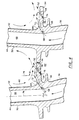
- FIG. 4 is a view taken along line 4-4 of FIG. 3 with arrows indicating the flow of cooling fluid and the interblade vortices.
- FIG. 1 illustrates a typical axial flow gas turbine engine 12.
- the gas turbine engine includes a compressor section 14, a combustor 16, and a turbine section 18.
- a flow path 22 extends axially through the gas turbine engine and defines a passage for working fluid to pass sequentially through the compressor section, the combustor and the turbine section.
- the turbine section includes a plurality of rotor assemblies 24, each rotor assembly including a rotatable disk 26 and a plurality of circumferentially spaced rotor blades 28 extending radially from the disk.
- each rotor blade includes an airfoil portion 32 which extends through the flow path, an integral platform 34 which extends laterally about the rotor blade and a root portion 36 which engages the disk to retain the rotor blade to the disk.
- the airfoil portion includes a leading edge 38, a pressure surface 42, a suction surface 44, and a trailing edge 46.
- the airfoil portion is hollow and is within fluid communication with cooling passages 48 through the root portion.
- the cooling passages of the root portion are in fluid communication with a source of high pressure cooling fluid, typically a supply of compressor air which bypasses the combustion process.
- a source of high pressure cooling fluid typically a supply of compressor air which bypasses the combustion process.
- the cooling fluid within the airfoil section is typically expelled through cooling holes which extend between the hollow air portion and the flow path.
- the platform includes an outer surface 52 which extends laterally to be in close proximity to the platform of an adjacent rotor blade.
- the plurality of platforms and their outer surfaces define a radially inner flow surface for working fluid within the flow path. In this way the platforms confined the working medium to the airfoil portion of the rotor blade to maximize the interaction between the airfoil portion and the working fluid and the efficiency of the energy transfer between the working fluid and the airfoil portion.
- the platform also includes an underside 54, a plurality of first cooling holes 56, and a plurality of second cooling holes 58.
- the underside of the platforms defines in part a damper cavity 62 (see FIG. 4) between adjacent rotor blade root portions.
- the damper cavity typically retains vibration damping means to minimize the vibration of the rotor blade during operation.
- the plurality of first cooling holes extend along the pressure surface of the airfoil from the leading edge to the trailing edge. This set of cooling holes approximates the shape of the pressure surface of the airfoil as shown in FIGs. 3 and 4,.
- Each of the first cooling holes extends between a core cooling passage and the platform outer surface and is disposed radially between the platform-to airfoil-fillet 64 and a platform-to-root fillet 66.
- the first cooling hole includes an inlet 68 which provides means of fluid communication between the core passage and the cooling hole and an outlet 72 which provides means of communication between the cooling hole and the flow path.
- Each of the first cooling holes is angled relative to the radial axis 74 such that cooling fluid is directed radially outward and laterally away from the pressure surface of the airfoil.
- the outlet of each of the first cooling holes is shaped to provide diffusion of the cooling fluid exiting the first cooling hole. Diffusing the exiting cooling fluid spreads the cooling fluid over a greater area and lowers the flow velocity of the cooling fluid. Lowering the velocity increases the likelihood that the cooling fluid will not separate from the surface and will form a film over the surface.
- the plurality of second cooling holes extend between the damper cavity and the platform outer surface and include an inlet 76 providing fluid communication between the second cooling hole and the damper cavity and an outlet 78 providing fluid communication through the cooling hole and the flow path.
- Each of the second cooling holes is disposed along the laterally outward portion of the pressure side platform.
- the second cooling holes are also angled relative to the radial axis to direct cooling fluid radially outward and laterally away from the pressure surface of the airfoil portion.
- the exits of each of the second cooling holes is also shaped to provide means of diffusing the cooling fluid exiting the second cooling holes.
- an interblade vortice 82 extends between the adjacent blades and rotates about an axially oriented axis.
- the vortice is represented as a plurality of flow stream lines which indicate the direction of flow within the vortices.
- This vortice carries fluid radially inward along the pressure surface of each blade, then laterally between the pressure surface and the suction surface of an adjacent blade, and then radially outward along the suction surface.
- the effect of this vortice is to increase the total pressure along the surface of the platform nearest the airfoil pressure surface.
- the pressure along the outer surface decreases laterally outward from the pressure surface.
- Each of the first cooling holes and second cooling holes is aligned such that the direction of fluid flow through the cooling holes approximates the lateral direction of flow of the inner blade vortices near the outlet of each cooling hole.
- working fluid passes axially through the rotor blade assembly.
- Engagement of the working fluid and the plurality of rotor blades generates pressure variations along the outer surface of the platform.
- the vortices generate a pressure gradient which decays in a direction laterally outward from the pressure surface of the airfoil.
- pressure losses occur as the working fluid passes axially through the rotor blade assembly such that the region of the platform of the outer surface near the leading edge as a high pressure region and the pressure along the outer surface decays axially downstream from the leading edge.
- the resulting pressure feel along the outer surface has a relatively high pressure region forward of the leading edge and along the pressure surface junction with the outer surface of the platform.
- a relatively low pressure region exists at the laterally outward edge and at approximately at the mid span of the airfoil portion.
- core cooling fluid passes radially outward from the root portion towards the airfoil portion. A portion of this core cooling fluid passes through the first cooling hole inlets, along the first cooling holes and out the first cooling hole exits.
- the core cooling fluid is drawn from the compressor section and is relatively low temperature and relatively high pressure fluid as compared to the working fluid passing through the rotor assembly. This ensures that cooling fluid exiting the first cooling holes will flow radially outward and into the flow path. In addition this provides the coolest fluid in the region of the platform subject to the highest temperatures.
- the second cooling holes use the cooling fluid within the damper cavity as a source of cooling fluid.
- Fluid within the damper cavity consists of cooling fluid from the compressor section which has leaked around various seals and which has followed a tortuous path before flowing into the damper cavity.
- the cooling fluid within the damper cavity is at a lower pressure and higher temperature than the core cooling fluid. For this reason this cooling fluid may be at too low a pressure to be used as cooling fluid in the higher pressure regions of the platform. Use of this cooling fluid may lead to ingestion of working fluid into the damper cavity and thereby degrade the rotor assembly.
- the damper cavity cooling fluid may be ejected out into the lower pressure regions of the platform, as shown in FIGs. 2, 3 and 4.
- first cooling holes and second cooling holes The fluid exiting the first cooling holes and the second cooling holes does so at an angle relative to the radial axis such that is encouraged to flow laterally over the outer surface.
- the fluid exiting the first cooling holes and second cooling holes engages the flow within the vortices which further encourages the cooling fluid to flow over the outer surface in a lateral direction between the pressure surface and suction surface.
- the combination of first cooling holes and second cooling holes as shown in FIGs. 2 and 3 provides a film or blanket of cooling fluid over the pressure surface side of the platform, with the coolest highest pressure fluid being concentrated in the high pressure high temperature region of the platform and with the remaining cooling fluid concentrated in the lower pressure region of the platform. In this way the effectiveness of the platform cooling is optimized and the amount of cooling fluid necessary to cool a platform is thereby minimized.
Abstract
Description
Claims (4)
- A rotor blade (28) for an axial flow gas turbine engine (12) disposed about a longitudinal axis, the gas turbine engine including an axially directed flow path (22) defining a passage for working fluid, a rotor assembly (24) including a rotatable disk (26) and the rotor blade (28), and a source of cooling fluid, the rotor blade (28) including an airfoil section (32) extending through the flow path (22), the airfoil portion (32) including a pressure surface (42) and a suction surface (44), the airfoil portion (32) having a hollow core, a root portion (36) disposed radially inward of the airfoil portion (32) and engaged with the disk (26) to secure the blade (28) to the disk (26), the root portion (36) including a core path defining a flow path for cooling fluid, the core path being in fluid communication with the source of cooling fluid and with the hollow core of the airfoil portion (32), and a platform (34) extending laterally from the blade (28) and disposed radially between the airfoil portion (32) and the root portion (36), the platform (34) including an outer surface (52) defining a flow surface for the flow path (22), a first fillet (64) adjoining the outer surface (52) and the airfoil portion (32), an inner surface (54) defining in part an under platform cavity (62), and a second fillet (66) adjoining the inner surface (54) and the root portion (36), wherein the rotor blade (28) is characterized by including:
a first cooling hole (56) that extends between the core path and the outer surface (52), the first cooling hole (56) being disposed radially inward of the first fillet (64) and radially outward of the second fillet (66), the first cooling hole (56) having an inlet (68) disposed in the core path and an exit (72) disposed on the outer surface (52) and laterally outward of the first fillet (64), and a second cooling hole (58) that extends between the under platform cavity (62) and the outer surface (52), the second cooling hole (58) including an inlet (76) disposed on the inner surface (54) and an exit (78) disposed on the outer surface (52), the second cooling hole exit (78) disposed laterally outward of the first cooling hole exit (72). - The rotor blade (28) according to claim 1, wherein the rotor assembly (24) includes a plurality of rotor blades (28) spaced circumferentially about the disk (26), the spacing being such that an interblade vortex (82) is generated between adjacent blades (28), the interblade vortex (82) having an axially oriented axis and a plurality of flow streamlines extending between adjacent blades, and wherein the first cooling hole (56) includes a first cooling hole axis oriented in the direction of flow through the first cooling hole (56), the first cooling hole axis being aligned with one of the flow streamlines, and wherein the second cooling hole (58) includes a second cooling hole axis oriented in the direction of flow through the second cooling hole (58), the second cooling hole axis being aligned with one of the flow streamlines.
- A rotor assembly (24) for a gas turbine engine (12) disposed about a longitudinal axis, the gas turbine engine (12) including an axially directed flowpath (22) defining a passage for working fluid and a source of cooling fluid, the rotor assembly (24) including a rotatable disk (26), and a plurality of rotor blades (28), wherein each of the plurality of rotor blades (28) includes an airfoil section (32) extending through the flow path (22), the airfoil portion (32) including a pressure surface (42) and a suction surface (44), the airfoil portion (32) having a hollow core, a root portion (36) disposed radially inward of the airfoil portion (32) and engaged with the disk (26) to secure the blade (28) to the disk (26), the root portion (36) including a core path defining a flow path for cooling fluid, the core path being in fluid communication with the source of cooling fluid and with the hollow core of the airfoil portion (32), and a platform (34) extending laterally from the blade (28) and disposed radially between the airfoil portion (32) and the root portion (36), the platform (34) including an outer surface (52) defining a flow surface for the flow path (22), a first fillet (64) adjoining the outer surface (52) and the airfoil portion (32), an inner surface (54) defining in part an under platform cavity (62), and a second fillet (66) adjoining the inner surface (54) and the root portion (36), wherein the rotor assembly (24) is characterized by including:
a first cooling hole (56) that extends between the core path and the outer surface (52), the first cooling hole (56) being disposed radially inward of the first fillet (64) and radially outward of the second fillet (66), the first cooling hole (56) having an inlet (68) disposed in the core path and an exit (72) disposed on the outer surface (52) and laterally outward of the first fillet (64), and a second cooling hole (58) that extends between the under platform cavity (62) and the outer surface (52), the second cooling hole (58) including an inlet (76) disposed on the inner surface (54) and an exit (78) disposed on the outer surface (52), the second cooling hole exit (78) disposed laterally outward of the first cooling hole exit (72). - The rotor assembly (24) according to Claim 3, wherein the plurality of rotor blades (28) are spaced circumferentially about the disk (26), the spacing being such that an interblade vortex (82) is generated between adjacent blades (28), the interblade vortex (82) having an axially oriented axis and a plurality of flow streamlines extending between adjacent blades (28), and wherein the first cooling hole (56) includes a first cooling hole axis oriented in the direction of flow through the first cooling hole (56) the first cooling hole axis being aligned with one of the flow streamlines, and wherein the second cooling hole (58) includes a second cooling hole axis oriented in the direction of flow through the second cooling hole (58), the second cooling hole axis being aligned with one of the flow streamlines.
Applications Claiming Priority (3)
| Application Number | Priority Date | Filing Date | Title |
|---|---|---|---|
| US98085092A | 1992-11-24 | 1992-11-24 | |
| PCT/US1993/010937 WO1994012765A1 (en) | 1992-11-24 | 1993-11-12 | Rotor blade with cooled integral platform |
| US980850 | 1997-11-29 |
Publications (2)
| Publication Number | Publication Date |
|---|---|
| EP0702748A1 EP0702748A1 (en) | 1996-03-27 |
| EP0702748B1 true EP0702748B1 (en) | 1998-09-23 |
Family
ID=25527898
Family Applications (1)
| Application Number | Title | Priority Date | Filing Date |
|---|---|---|---|
| EP94900616A Expired - Lifetime EP0702748B1 (en) | 1992-11-24 | 1993-11-12 | Rotor blade with cooled integral platform |
Country Status (4)
| Country | Link |
|---|---|
| US (1) | US5382135A (en) |
| EP (1) | EP0702748B1 (en) |
| DE (1) | DE69321261T2 (en) |
| WO (1) | WO1994012765A1 (en) |
Cited By (1)
| Publication number | Priority date | Publication date | Assignee | Title |
|---|---|---|---|---|
| US7097417B2 (en) | 2004-02-09 | 2006-08-29 | Siemens Westinghouse Power Corporation | Cooling system for an airfoil vane |
Families Citing this family (110)
| Publication number | Priority date | Publication date | Assignee | Title |
|---|---|---|---|---|
| US5482435A (en) * | 1994-10-26 | 1996-01-09 | Westinghouse Electric Corporation | Gas turbine blade having a cooled shroud |
| US5503529A (en) * | 1994-12-08 | 1996-04-02 | General Electric Company | Turbine blade having angled ejection slot |
| US5779437A (en) * | 1996-10-31 | 1998-07-14 | Pratt & Whitney Canada Inc. | Cooling passages for airfoil leading edge |
| US5735671A (en) * | 1996-11-29 | 1998-04-07 | General Electric Company | Shielded turbine rotor |
| FR2758855B1 (en) * | 1997-01-30 | 1999-02-26 | Snecma | VENTILATION SYSTEM FOR MOBILE VANE PLATFORMS |
| JP3758792B2 (en) * | 1997-02-25 | 2006-03-22 | 三菱重工業株式会社 | Gas turbine rotor platform cooling mechanism |
| JP3411775B2 (en) * | 1997-03-10 | 2003-06-03 | 三菱重工業株式会社 | Gas turbine blade |
| DE59710924D1 (en) | 1997-09-15 | 2003-12-04 | Alstom Switzerland Ltd | Cooling device for gas turbine components |
| CA2262064C (en) * | 1998-02-23 | 2002-09-03 | Mitsubishi Heavy Industries, Ltd. | Gas turbine moving blade platform |
| US6190130B1 (en) * | 1998-03-03 | 2001-02-20 | Mitsubishi Heavy Industries, Ltd. | Gas turbine moving blade platform |
| US6065931A (en) * | 1998-03-05 | 2000-05-23 | Mitsubishi Heavy Industries, Ltd. | Gas turbine moving blade |
| US6176678B1 (en) | 1998-11-06 | 2001-01-23 | General Electric Company | Apparatus and methods for turbine blade cooling |
| DE59810806D1 (en) | 1998-12-10 | 2004-03-25 | Alstom Switzerland Ltd | Platform cooling in turbomachinery |
| DE19941134C1 (en) * | 1999-08-30 | 2000-12-28 | Mtu Muenchen Gmbh | Blade crown ring for gas turbine aircraft engine has each blade provided with transition region between blade surface and blade platform having successively decreasing curvature radii |
| JP3782637B2 (en) * | 2000-03-08 | 2006-06-07 | 三菱重工業株式会社 | Gas turbine cooling vane |
| US6354797B1 (en) * | 2000-07-27 | 2002-03-12 | General Electric Company | Brazeless fillet turbine nozzle |
| GB2365079B (en) * | 2000-07-29 | 2004-09-22 | Rolls Royce Plc | Blade platform cooling |
| US6341939B1 (en) * | 2000-07-31 | 2002-01-29 | General Electric Company | Tandem cooling turbine blade |
| DE10064265A1 (en) * | 2000-12-22 | 2002-07-04 | Alstom Switzerland Ltd | Device and method for cooling a platform of a turbine blade |
| JP4508432B2 (en) * | 2001-01-09 | 2010-07-21 | 三菱重工業株式会社 | Gas turbine cooling structure |
| GB2395987B (en) * | 2002-12-02 | 2005-12-21 | Alstom | Turbine blade with cooling bores |
| GB2402442B (en) * | 2003-06-04 | 2006-05-31 | Rolls Royce Plc | Cooled nozzled guide vane or turbine rotor blade platform |
| US6830432B1 (en) * | 2003-06-24 | 2004-12-14 | Siemens Westinghouse Power Corporation | Cooling of combustion turbine airfoil fillets |
| US6945749B2 (en) * | 2003-09-12 | 2005-09-20 | Siemens Westinghouse Power Corporation | Turbine blade platform cooling system |
| DE102004029696A1 (en) * | 2004-06-15 | 2006-01-05 | Rolls-Royce Deutschland Ltd & Co Kg | Platform cooling arrangement for the vane ring of a gas turbine |
| US7198467B2 (en) * | 2004-07-30 | 2007-04-03 | General Electric Company | Method and apparatus for cooling gas turbine engine rotor blades |
| US7131817B2 (en) * | 2004-07-30 | 2006-11-07 | General Electric Company | Method and apparatus for cooling gas turbine engine rotor blades |
| US7144215B2 (en) * | 2004-07-30 | 2006-12-05 | General Electric Company | Method and apparatus for cooling gas turbine engine rotor blades |
| US7217096B2 (en) * | 2004-12-13 | 2007-05-15 | General Electric Company | Fillet energized turbine stage |
| US7249933B2 (en) * | 2005-01-10 | 2007-07-31 | General Electric Company | Funnel fillet turbine stage |
| US20060269409A1 (en) * | 2005-05-27 | 2006-11-30 | Mitsubishi Heavy Industries, Ltd. | Gas turbine moving blade having a platform, a method of forming the moving blade, a sealing plate, and a gas turbine having these elements |
| US7244101B2 (en) * | 2005-10-04 | 2007-07-17 | General Electric Company | Dust resistant platform blade |
| US7309212B2 (en) * | 2005-11-21 | 2007-12-18 | General Electric Company | Gas turbine bucket with cooled platform leading edge and method of cooling platform leading edge |
| US7322797B2 (en) * | 2005-12-08 | 2008-01-29 | General Electric Company | Damper cooled turbine blade |
| US7416391B2 (en) * | 2006-02-24 | 2008-08-26 | General Electric Company | Bucket platform cooling circuit and method |
| US7597536B1 (en) | 2006-06-14 | 2009-10-06 | Florida Turbine Technologies, Inc. | Turbine airfoil with de-coupled platform |
| US7695247B1 (en) | 2006-09-01 | 2010-04-13 | Florida Turbine Technologies, Inc. | Turbine blade platform with near-wall cooling |
| US7762773B2 (en) * | 2006-09-22 | 2010-07-27 | Siemens Energy, Inc. | Turbine airfoil cooling system with platform edge cooling channels |
| US7927073B2 (en) * | 2007-01-04 | 2011-04-19 | Siemens Energy, Inc. | Advanced cooling method for combustion turbine airfoil fillets |
| US7819629B2 (en) * | 2007-02-15 | 2010-10-26 | Siemens Energy, Inc. | Blade for a gas turbine |
| JP5281245B2 (en) * | 2007-02-21 | 2013-09-04 | 三菱重工業株式会社 | Gas turbine rotor platform cooling structure |
| US7621718B1 (en) | 2007-03-28 | 2009-11-24 | Florida Turbine Technologies, Inc. | Turbine vane with leading edge fillet region impingement cooling |
| US7766618B1 (en) | 2007-06-21 | 2010-08-03 | Florida Turbine Technologies, Inc. | Turbine vane endwall with cascading film cooling diffusion slots |
| US8011892B2 (en) * | 2007-06-28 | 2011-09-06 | United Technologies Corporation | Turbine blade nested seal and damper assembly |
| US8844129B2 (en) * | 2007-10-15 | 2014-09-30 | United Technologies Corporation | Method and apparatus for hole crack removal |
| US8197209B2 (en) * | 2007-12-19 | 2012-06-12 | United Technologies Corp. | Systems and methods involving variable throat area vanes |
| FR2927356B1 (en) * | 2008-02-07 | 2013-03-01 | Snecma | AUBES FOR WHEEL WITH TURBOMACHINE AUBES WITH GROOVE FOR COOLING. |
| US8206114B2 (en) * | 2008-04-29 | 2012-06-26 | United Technologies Corporation | Gas turbine engine systems involving turbine blade platforms with cooling holes |
| US8240987B2 (en) * | 2008-08-15 | 2012-08-14 | United Technologies Corp. | Gas turbine engine systems involving baffle assemblies |
| US8057178B2 (en) * | 2008-09-04 | 2011-11-15 | General Electric Company | Turbine bucket for a turbomachine and method of reducing bow wave effects at a turbine bucket |
| DE102008060424A1 (en) * | 2008-12-04 | 2010-06-10 | Rolls-Royce Deutschland Ltd & Co Kg | Turbomachine with sidewall boundary layer barrier |
| JP5317014B2 (en) * | 2009-03-18 | 2013-10-16 | 株式会社Ihi | Turbine blade |
| US8356978B2 (en) * | 2009-11-23 | 2013-01-22 | United Technologies Corporation | Turbine airfoil platform cooling core |
| US9630277B2 (en) * | 2010-03-15 | 2017-04-25 | Siemens Energy, Inc. | Airfoil having built-up surface with embedded cooling passage |
| US8647064B2 (en) | 2010-08-09 | 2014-02-11 | General Electric Company | Bucket assembly cooling apparatus and method for forming the bucket assembly |
| US9416666B2 (en) | 2010-09-09 | 2016-08-16 | General Electric Company | Turbine blade platform cooling systems |
| US8684664B2 (en) | 2010-09-30 | 2014-04-01 | General Electric Company | Apparatus and methods for cooling platform regions of turbine rotor blades |
| US8794921B2 (en) | 2010-09-30 | 2014-08-05 | General Electric Company | Apparatus and methods for cooling platform regions of turbine rotor blades |
| US8777568B2 (en) | 2010-09-30 | 2014-07-15 | General Electric Company | Apparatus and methods for cooling platform regions of turbine rotor blades |
| US8814517B2 (en) | 2010-09-30 | 2014-08-26 | General Electric Company | Apparatus and methods for cooling platform regions of turbine rotor blades |
| US8851846B2 (en) | 2010-09-30 | 2014-10-07 | General Electric Company | Apparatus and methods for cooling platform regions of turbine rotor blades |
| US8840369B2 (en) | 2010-09-30 | 2014-09-23 | General Electric Company | Apparatus and methods for cooling platform regions of turbine rotor blades |
| US20120087803A1 (en) * | 2010-10-12 | 2012-04-12 | General Electric Company | Curved film cooling holes for turbine airfoil and related method |
| US8814518B2 (en) | 2010-10-29 | 2014-08-26 | General Electric Company | Apparatus and methods for cooling platform regions of turbine rotor blades |
| US8636471B2 (en) | 2010-12-20 | 2014-01-28 | General Electric Company | Apparatus and methods for cooling platform regions of turbine rotor blades |
| GB201103176D0 (en) * | 2011-02-24 | 2011-04-06 | Rolls Royce Plc | Endwall component for a turbine stage of a gas turbine engine |
| WO2012140806A1 (en) * | 2011-04-14 | 2012-10-18 | 三菱重工業株式会社 | Gas turbine rotor blade and gas turbine |
| US8915712B2 (en) * | 2011-06-20 | 2014-12-23 | General Electric Company | Hot gas path component |
| US8734111B2 (en) | 2011-06-27 | 2014-05-27 | General Electric Company | Platform cooling passages and methods for creating platform cooling passages in turbine rotor blades |
| US8961135B2 (en) | 2011-06-29 | 2015-02-24 | Siemens Energy, Inc. | Mateface gap configuration for gas turbine engine |
| JP2011241836A (en) * | 2011-08-02 | 2011-12-01 | Mitsubishi Heavy Ind Ltd | Platform cooling structure of gas turbine moving blade |
| US9447691B2 (en) * | 2011-08-22 | 2016-09-20 | General Electric Company | Bucket assembly treating apparatus and method for treating bucket assembly |
| US8858160B2 (en) | 2011-11-04 | 2014-10-14 | General Electric Company | Bucket assembly for turbine system |
| US8840370B2 (en) | 2011-11-04 | 2014-09-23 | General Electric Company | Bucket assembly for turbine system |
| US9022735B2 (en) | 2011-11-08 | 2015-05-05 | General Electric Company | Turbomachine component and method of connecting cooling circuits of a turbomachine component |
| PL2615243T3 (en) * | 2012-01-11 | 2017-12-29 | MTU Aero Engines AG | Blade ring segment for a fluid flow engine and method for producing the same |
| US9109454B2 (en) | 2012-03-01 | 2015-08-18 | General Electric Company | Turbine bucket with pressure side cooling |
| US9127561B2 (en) | 2012-03-01 | 2015-09-08 | General Electric Company | Turbine bucket with contoured internal rib |
| US8974182B2 (en) | 2012-03-01 | 2015-03-10 | General Electric Company | Turbine bucket with a core cavity having a contoured turn |
| US9482098B2 (en) * | 2012-05-11 | 2016-11-01 | United Technologies Corporation | Convective shielding cooling hole pattern |
| US9243503B2 (en) * | 2012-05-23 | 2016-01-26 | General Electric Company | Components with microchannel cooled platforms and fillets and methods of manufacture |
| US10180067B2 (en) | 2012-05-31 | 2019-01-15 | United Technologies Corporation | Mate face cooling holes for gas turbine engine component |
| US9644903B1 (en) * | 2012-06-01 | 2017-05-09 | The United States Of America As Represented By The Administrator Of National Aeronautics And Space Administration | Shaped recess flow control |
| US9021816B2 (en) | 2012-07-02 | 2015-05-05 | United Technologies Corporation | Gas turbine engine turbine vane platform core |
| US9091180B2 (en) | 2012-07-19 | 2015-07-28 | Siemens Energy, Inc. | Airfoil assembly including vortex reducing at an airfoil leading edge |
| US20140064984A1 (en) * | 2012-08-31 | 2014-03-06 | General Electric Company | Cooling arrangement for platform region of turbine rotor blade |
| US9121292B2 (en) | 2012-12-05 | 2015-09-01 | General Electric Company | Airfoil and a method for cooling an airfoil platform |
| WO2014186005A2 (en) | 2013-02-15 | 2014-11-20 | United Technologies Corporation | Gas turbine engine component with combined mate face and platform cooling |
| EP2959130B1 (en) * | 2013-02-19 | 2019-10-09 | United Technologies Corporation | Gas turbine engine blade, core for manufacturing said blade, and method for manufacturing said core |
| EP3047107B1 (en) * | 2013-09-17 | 2022-02-23 | Raytheon Technologies Corporation | Gas turbine engine component platform seal cooling |
| EP3047106B1 (en) * | 2013-09-19 | 2020-09-02 | United Technologies Corporation | Gas turbine engine airfoil having serpentine fed platform cooling passage |
| KR101833660B1 (en) * | 2014-04-03 | 2018-02-28 | 미츠비시 히타치 파워 시스템즈 가부시키가이샤 | Vane array and gas turbine |
| JP5606648B1 (en) | 2014-06-27 | 2014-10-15 | 三菱日立パワーシステムズ株式会社 | Rotor blade and gas turbine provided with the same |
| US9708916B2 (en) | 2014-07-18 | 2017-07-18 | General Electric Company | Turbine bucket plenum for cooling flows |
| US10465523B2 (en) | 2014-10-17 | 2019-11-05 | United Technologies Corporation | Gas turbine component with platform cooling |
| US9957894B2 (en) * | 2015-02-20 | 2018-05-01 | United Technologies Corporation | Outer diameter platform cooling hole system and assembly |
| US10053989B2 (en) | 2015-12-21 | 2018-08-21 | General Electric Company | Cooling circuit for a multi-wall blade |
| US10030526B2 (en) * | 2015-12-21 | 2018-07-24 | General Electric Company | Platform core feed for a multi-wall blade |
| US10119405B2 (en) | 2015-12-21 | 2018-11-06 | General Electric Company | Cooling circuit for a multi-wall blade |
| US10060269B2 (en) | 2015-12-21 | 2018-08-28 | General Electric Company | Cooling circuits for a multi-wall blade |
| US10208608B2 (en) | 2016-08-18 | 2019-02-19 | General Electric Company | Cooling circuit for a multi-wall blade |
| US10221696B2 (en) | 2016-08-18 | 2019-03-05 | General Electric Company | Cooling circuit for a multi-wall blade |
| US10227877B2 (en) | 2016-08-18 | 2019-03-12 | General Electric Company | Cooling circuit for a multi-wall blade |
| US10267162B2 (en) | 2016-08-18 | 2019-04-23 | General Electric Company | Platform core feed for a multi-wall blade |
| US10208607B2 (en) | 2016-08-18 | 2019-02-19 | General Electric Company | Cooling circuit for a multi-wall blade |
| KR102000836B1 (en) * | 2017-09-27 | 2019-07-16 | 두산중공업 주식회사 | Gas Turbine |
| US20190264569A1 (en) * | 2018-02-23 | 2019-08-29 | General Electric Company | Turbine rotor blade with exiting hole to deliver fluid to boundary layer film |
| FR3095003B1 (en) * | 2019-04-15 | 2022-07-08 | Safran Aircraft Engines | Turbine blade having a platform cooling slot |
| CN113404549A (en) * | 2021-07-26 | 2021-09-17 | 中国船舶重工集团公司第七0三研究所 | Turbine movable vane with root-extending air supply hole and edge plate air film hole |
| IT202200001355A1 (en) * | 2022-01-27 | 2023-07-27 | Nuovo Pignone Tecnologie Srl | GAS TURBINE NOZZLES WITH REFRIGERATION AND TURBINE HOLES |
Family Cites Families (20)
| Publication number | Priority date | Publication date | Assignee | Title |
|---|---|---|---|---|
| GB678085A (en) * | 1949-02-15 | 1952-08-27 | Rolls Royce | Improvements in or relating to compressors and turbines |
| US2737366A (en) * | 1950-05-02 | 1956-03-06 | Simmering Graz Pauker Ag | Gas turbine |
| GB742288A (en) * | 1951-02-15 | 1955-12-21 | Power Jets Res & Dev Ltd | Improvements in the cooling of turbines |
| CH343580A (en) * | 1955-07-18 | 1959-12-31 | Power Jets Res & Dev Ltd | Axial compressor |
| US3066910A (en) * | 1958-07-09 | 1962-12-04 | Thompson Ramo Wooldridge Inc | Cooled turbine blade |
| US3446482A (en) * | 1967-03-24 | 1969-05-27 | Gen Electric | Liquid cooled turbine rotor |
| US3446481A (en) * | 1967-03-24 | 1969-05-27 | Gen Electric | Liquid cooled turbine rotor |
| US4040767A (en) * | 1975-06-02 | 1977-08-09 | United Technologies Corporation | Coolable nozzle guide vane |
| US4017213A (en) * | 1975-10-14 | 1977-04-12 | United Technologies Corporation | Turbomachinery vane or blade with cooled platforms |
| US4137619A (en) * | 1977-10-03 | 1979-02-06 | General Electric Company | Method of fabricating composite structures for water cooled gas turbine components |
| FR2438157A1 (en) * | 1978-10-05 | 1980-04-30 | Alsthom Atlantique | BLADE GRILLE FOR TURBINE OR COMPRESSOR |
| US4350473A (en) * | 1980-02-22 | 1982-09-21 | General Electric Company | Liquid cooled counter flow turbine bucket |
| GB2119027A (en) * | 1982-04-24 | 1983-11-09 | Rolls Royce | Turbine assembly for a gas turbine engine |
| US4672727A (en) * | 1985-12-23 | 1987-06-16 | United Technologies Corporation | Method of fabricating film cooling slot in a hollow airfoil |
| US4676719A (en) * | 1985-12-23 | 1987-06-30 | United Technologies Corporation | Film coolant passages for cast hollow airfoils |
| DE3850681T2 (en) * | 1987-02-06 | 1995-03-09 | Wolfgang P Weinhold | Rotor blade. |
| JP2862536B2 (en) * | 1987-09-25 | 1999-03-03 | 株式会社東芝 | Gas turbine blades |
| GB2227965B (en) * | 1988-10-12 | 1993-02-10 | Rolls Royce Plc | Apparatus for drilling a shaped hole in a workpiece |
| US5122033A (en) * | 1990-11-16 | 1992-06-16 | Paul Marius A | Turbine blade unit |
| GB2253443A (en) * | 1991-03-05 | 1992-09-09 | Rolls Royce Plc | Gas turbine nozzle guide vane arrangement |
-
1993
- 1993-10-20 US US08/139,625 patent/US5382135A/en not_active Expired - Lifetime
- 1993-11-12 WO PCT/US1993/010937 patent/WO1994012765A1/en active IP Right Grant
- 1993-11-12 DE DE69321261T patent/DE69321261T2/en not_active Expired - Lifetime
- 1993-11-12 EP EP94900616A patent/EP0702748B1/en not_active Expired - Lifetime
Cited By (1)
| Publication number | Priority date | Publication date | Assignee | Title |
|---|---|---|---|---|
| US7097417B2 (en) | 2004-02-09 | 2006-08-29 | Siemens Westinghouse Power Corporation | Cooling system for an airfoil vane |
Also Published As
| Publication number | Publication date |
|---|---|
| EP0702748A1 (en) | 1996-03-27 |
| DE69321261D1 (en) | 1998-10-29 |
| US5382135A (en) | 1995-01-17 |
| DE69321261T2 (en) | 1999-05-20 |
| WO1994012765A1 (en) | 1994-06-09 |
Similar Documents
| Publication | Publication Date | Title |
|---|---|---|
| EP0702748B1 (en) | Rotor blade with cooled integral platform | |
| US5340278A (en) | Rotor blade with integral platform and a fillet cooling passage | |
| US5800124A (en) | Cooled rotor assembly for a turbine engine | |
| US5344283A (en) | Turbine vane having dedicated inner platform cooling | |
| US5288207A (en) | Internally cooled turbine airfoil | |
| US5197852A (en) | Nozzle band overhang cooling | |
| CA2725801C (en) | Rotor assembly with cooling air deflectors and method | |
| US6120249A (en) | Gas turbine blade platform cooling concept | |
| EP1764484B1 (en) | Turbine cooling air sealing with associated turbine engine and method for reengineering a gas turbine engine | |
| EP0808413B1 (en) | Configuration of the bent parts of serpentine cooling channels for turbine shrouds | |
| EP0768448B1 (en) | Cooled turbine vane assembly | |
| EP0753100B1 (en) | Turbine shroud segment with serpentine cooling channels | |
| EP0777818B1 (en) | Gas turbine blade with cooled platform | |
| JP4659206B2 (en) | Turbine nozzle with graded film cooling | |
| US6200087B1 (en) | Pressure compensated turbine nozzle | |
| EP0774047A1 (en) | Turbine airfoil with diffusing pedestals in its trailing edge | |
| CA1311133C (en) | Radial turbine wheel | |
| JP3417417B2 (en) | Outer air seal device for gas turbine engine that can be cooled | |
| US4302148A (en) | Gas turbine engine having a cooled turbine | |
| US5097660A (en) | Coanda effect turbine nozzle vane cooling | |
| GB2042643A (en) | Cooled Gas Turbine Engine |
Legal Events
| Date | Code | Title | Description |
|---|---|---|---|
| PUAI | Public reference made under article 153(3) epc to a published international application that has entered the european phase |
Free format text: ORIGINAL CODE: 0009012 |
|
| 17P | Request for examination filed |
Effective date: 19951006 |
|
| AK | Designated contracting states |
Kind code of ref document: A1 Designated state(s): DE FR GB |
|
| GRAG | Despatch of communication of intention to grant |
Free format text: ORIGINAL CODE: EPIDOS AGRA |
|
| 17Q | First examination report despatched |
Effective date: 19980122 |
|
| GRAG | Despatch of communication of intention to grant |
Free format text: ORIGINAL CODE: EPIDOS AGRA |
|
| GRAH | Despatch of communication of intention to grant a patent |
Free format text: ORIGINAL CODE: EPIDOS IGRA |
|
| GRAH | Despatch of communication of intention to grant a patent |
Free format text: ORIGINAL CODE: EPIDOS IGRA |
|
| GRAA | (expected) grant |
Free format text: ORIGINAL CODE: 0009210 |
|
| AK | Designated contracting states |
Kind code of ref document: B1 Designated state(s): DE FR GB |
|
| REF | Corresponds to: |
Ref document number: 69321261 Country of ref document: DE Date of ref document: 19981029 |
|
| ET | Fr: translation filed | ||
| PLBE | No opposition filed within time limit |
Free format text: ORIGINAL CODE: 0009261 |
|
| STAA | Information on the status of an ep patent application or granted ep patent |
Free format text: STATUS: NO OPPOSITION FILED WITHIN TIME LIMIT |
|
| 26N | No opposition filed | ||
| REG | Reference to a national code |
Ref country code: GB Ref legal event code: IF02 |
|
| PGFP | Annual fee paid to national office [announced via postgrant information from national office to epo] |
Ref country code: FR Payment date: 20071105 Year of fee payment: 15 |
|
| REG | Reference to a national code |
Ref country code: FR Ref legal event code: ST Effective date: 20090731 |
|
| PG25 | Lapsed in a contracting state [announced via postgrant information from national office to epo] |
Ref country code: FR Free format text: LAPSE BECAUSE OF NON-PAYMENT OF DUE FEES Effective date: 20081130 |
|
| PGFP | Annual fee paid to national office [announced via postgrant information from national office to epo] |
Ref country code: DE Payment date: 20121107 Year of fee payment: 20 |
|
| PGFP | Annual fee paid to national office [announced via postgrant information from national office to epo] |
Ref country code: GB Payment date: 20121107 Year of fee payment: 20 |
|
| REG | Reference to a national code |
Ref country code: DE Ref legal event code: R071 Ref document number: 69321261 Country of ref document: DE |
|
| REG | Reference to a national code |
Ref country code: DE Ref legal event code: R071 Ref document number: 69321261 Country of ref document: DE |
|
| REG | Reference to a national code |
Ref country code: GB Ref legal event code: PE20 Expiry date: 20131111 |
|
| PG25 | Lapsed in a contracting state [announced via postgrant information from national office to epo] |
Ref country code: DE Free format text: LAPSE BECAUSE OF EXPIRATION OF PROTECTION Effective date: 20131113 Ref country code: GB Free format text: LAPSE BECAUSE OF EXPIRATION OF PROTECTION Effective date: 20131111 |