EP0702476A2 - Procédé de transmission multiple des niveaux pondéré et appareil de transmission et réception pour la transmission multiple des niveaux pondéré - Google Patents
Procédé de transmission multiple des niveaux pondéré et appareil de transmission et réception pour la transmission multiple des niveaux pondéré Download PDFInfo
- Publication number
- EP0702476A2 EP0702476A2 EP95111926A EP95111926A EP0702476A2 EP 0702476 A2 EP0702476 A2 EP 0702476A2 EP 95111926 A EP95111926 A EP 95111926A EP 95111926 A EP95111926 A EP 95111926A EP 0702476 A2 EP0702476 A2 EP 0702476A2
- Authority
- EP
- European Patent Office
- Prior art keywords
- multilevel
- transmission
- weighted
- hierarchic
- coding
- Prior art date
- Legal status (The legal status is an assumption and is not a legal conclusion. Google has not performed a legal analysis and makes no representation as to the accuracy of the status listed.)
- Withdrawn
Links
Images


Classifications
-
- H—ELECTRICITY
- H03—ELECTRONIC CIRCUITRY
- H03M—CODING; DECODING; CODE CONVERSION IN GENERAL
- H03M13/00—Coding, decoding or code conversion, for error detection or error correction; Coding theory basic assumptions; Coding bounds; Error probability evaluation methods; Channel models; Simulation or testing of codes
- H03M13/35—Unequal or adaptive error protection, e.g. by providing a different level of protection according to significance of source information or by adapting the coding according to the change of transmission channel characteristics
- H03M13/356—Unequal error protection [UEP]
-
- H—ELECTRICITY
- H04—ELECTRIC COMMUNICATION TECHNIQUE
- H04L—TRANSMISSION OF DIGITAL INFORMATION, e.g. TELEGRAPHIC COMMUNICATION
- H04L1/00—Arrangements for detecting or preventing errors in the information received
- H04L1/004—Arrangements for detecting or preventing errors in the information received by using forward error control
- H04L1/0056—Systems characterized by the type of code used
- H04L1/0067—Rate matching
- H04L1/0068—Rate matching by puncturing
-
- H—ELECTRICITY
- H03—ELECTRONIC CIRCUITRY
- H03M—CODING; DECODING; CODE CONVERSION IN GENERAL
- H03M13/00—Coding, decoding or code conversion, for error detection or error correction; Coding theory basic assumptions; Coding bounds; Error probability evaluation methods; Channel models; Simulation or testing of codes
- H03M13/25—Error detection or forward error correction by signal space coding, i.e. adding redundancy in the signal constellation, e.g. Trellis Coded Modulation [TCM]
-
- H—ELECTRICITY
- H03—ELECTRONIC CIRCUITRY
- H03M—CODING; DECODING; CODE CONVERSION IN GENERAL
- H03M13/00—Coding, decoding or code conversion, for error detection or error correction; Coding theory basic assumptions; Coding bounds; Error probability evaluation methods; Channel models; Simulation or testing of codes
- H03M13/37—Decoding methods or techniques, not specific to the particular type of coding provided for in groups H03M13/03 - H03M13/35
- H03M13/39—Sequence estimation, i.e. using statistical methods for the reconstruction of the original codes
- H03M13/3905—Maximum a posteriori probability [MAP] decoding or approximations thereof based on trellis or lattice decoding, e.g. forward-backward algorithm, log-MAP decoding, max-log-MAP decoding
-
- H—ELECTRICITY
- H04—ELECTRIC COMMUNICATION TECHNIQUE
- H04L—TRANSMISSION OF DIGITAL INFORMATION, e.g. TELEGRAPHIC COMMUNICATION
- H04L1/00—Arrangements for detecting or preventing errors in the information received
- H04L1/004—Arrangements for detecting or preventing errors in the information received by using forward error control
- H04L1/0041—Arrangements at the transmitter end
-
- H—ELECTRICITY
- H04—ELECTRIC COMMUNICATION TECHNIQUE
- H04L—TRANSMISSION OF DIGITAL INFORMATION, e.g. TELEGRAPHIC COMMUNICATION
- H04L1/00—Arrangements for detecting or preventing errors in the information received
- H04L1/004—Arrangements for detecting or preventing errors in the information received by using forward error control
- H04L1/0056—Systems characterized by the type of code used
- H04L1/0059—Convolutional codes
- H04L1/006—Trellis-coded modulation
-
- H—ELECTRICITY
- H04—ELECTRIC COMMUNICATION TECHNIQUE
- H04L—TRANSMISSION OF DIGITAL INFORMATION, e.g. TELEGRAPHIC COMMUNICATION
- H04L1/00—Arrangements for detecting or preventing errors in the information received
- H04L1/004—Arrangements for detecting or preventing errors in the information received by using forward error control
- H04L1/0056—Systems characterized by the type of code used
- H04L1/007—Unequal error protection
-
- H—ELECTRICITY
- H04—ELECTRIC COMMUNICATION TECHNIQUE
- H04L—TRANSMISSION OF DIGITAL INFORMATION, e.g. TELEGRAPHIC COMMUNICATION
- H04L27/00—Modulated-carrier systems
- H04L27/32—Carrier systems characterised by combinations of two or more of the types covered by groups H04L27/02, H04L27/10, H04L27/18 or H04L27/26
- H04L27/34—Amplitude- and phase-modulated carrier systems, e.g. quadrature-amplitude modulated carrier systems
- H04L27/3405—Modifications of the signal space to increase the efficiency of transmission, e.g. reduction of the bit error rate, bandwidth, or average power
- H04L27/3416—Modifications of the signal space to increase the efficiency of transmission, e.g. reduction of the bit error rate, bandwidth, or average power in which the information is carried by both the individual signal points and the subset to which the individual points belong, e.g. using coset coding, lattice coding, or related schemes
- H04L27/3427—Modifications of the signal space to increase the efficiency of transmission, e.g. reduction of the bit error rate, bandwidth, or average power in which the information is carried by both the individual signal points and the subset to which the individual points belong, e.g. using coset coding, lattice coding, or related schemes in which the constellation is the n - fold Cartesian product of a single underlying two-dimensional constellation
- H04L27/3433—Modifications of the signal space to increase the efficiency of transmission, e.g. reduction of the bit error rate, bandwidth, or average power in which the information is carried by both the individual signal points and the subset to which the individual points belong, e.g. using coset coding, lattice coding, or related schemes in which the constellation is the n - fold Cartesian product of a single underlying two-dimensional constellation using an underlying square constellation
-
- H—ELECTRICITY
- H04—ELECTRIC COMMUNICATION TECHNIQUE
- H04L—TRANSMISSION OF DIGITAL INFORMATION, e.g. TELEGRAPHIC COMMUNICATION
- H04L1/00—Arrangements for detecting or preventing errors in the information received
- H04L2001/0098—Unequal error protection
Definitions
- This invention relates to a multilevel weighted transmission method which enables a reduction in the circuit scale of coding and decoding equipment and a transmission and reception apparatus using the multilevel weighted transmission method.
- transmission errors can take place on account of the influence of noise generated on the transmission path.
- error correction techniques are used.
- the error correction techniques were developed independently from modulation techniques. Recently, there have been strong demands toward a much greater transmission capacity under the band restrictions, and modulation techniques now in use range from BPSK, QPSK to 16QAM, and even to higher-level modulation schemes.
- TCM trellis-coded modulation
- transmission channel coding techniques for graceful degradation have been proposed which perform more powerful error correction on more important information by partitioning information source signals, such as video and audio signals, into a suitable number of levels hierarchically according to the degree of their importance, and allocating the level of error correction according to the degree of importance.
- FIG. 1 shows an example of a conventional transmission channel coding and decoding apparatus with the function of giving a weight to each level of hierarchy.
- the information source input signal is partitioned by an information source signal coding unit 11 into more important information Le2 and less important information Le1 (in this example, the number of hierarchic levels is 2).
- the pieces of information Le1 and Le2 undergo a coding process for error correction at a first FEC (Forward Error Correction) coding unit 39a and a second FEC coding unit 39b, respectively.
- the second FEC coding unit 39b effects heavier coding than the first FEC coding unit 39a: for example, the former effects weighting by more powerful FEC coding.
- each coded signal is subjected to a modulation process.
- the coded signals, the outputs of the FEC coding units 39a, 39b, are supplied to a first and second signal mapping distributors 23a, 23b, respectively.
- the first signal mapping distributor 23a converts the coded signal input into mapping data items Ie1, Qe1 to I-axis and Q-axis and supplies them to a first digital modulator 25a.
- the second signal mapping distributor 23b converts the coded signal input into mapping data items Ie2, Qe2 to I-axis and Q-axis and supplies them to a second digital modulator 25b.
- the analog signals obtained from the first and second digital modulators 25a, 25b are inputted to an adder 28, which adds them together and outputs the result as a transmission signal.
- mapping data items Ie1, Qe1, Ie2, Qe2 are assumed to realize the signal mapping in a modulation constellation according to the values of the modulation amplitude and phase (0° or 180° ) with respect to I-axis and Q-axis.
- Weighting according to modulation level is achieved by using, for example, a 16-QAM modulator as the first digital modulator 25a and a QPSK modulator as the second digital modulator 25b.
- the output data from the second digital modulator 25b has a smaller rate of data transmittable with a single symbol than that from the first digital modulator 25a (for QPSK, 2 bits per symbol, and for 16 QAM, 4 bits per symbol), but the error rate for the modulation symbol on the reception side is about 7 dB better in the carrier-to-noise ratio (hereinafter, abbreviated as C/N).
- a weight may be given to the power of modulation carrier as shown in FIG. 2.
- the output spectrum of the second digital modulator 25b has a higher power than that of the first digital modulator 25a, so that the former has a better anti-noise characteristic because of the power difference between the spectra with respect to white noise having the same level of energy.
- the data rate of information Le2 must be made lower than that of information Le1 in connection with the transmission rate for each level of hierarchy on account of the restrictions on the total transmission power.
- the transmission signal (intermediate-frequency signal) shown in FIG. 1 is actually converted into a broadcasting channel signal, which is converted into the original intermediate-frequency signal on the reception side to become the reception signal shown in FIG. 1.
- the reception signal is demodulated and A/D (analog-to-digital) converted at a first digital demodulator 55a and a second digital demodulator 55b, and are separated into I-axis mapping data items Id1, Id2 and Q-axis mapping data items Qd1, Qd2. These correspond to mapping data items Ie1, Ie2, Qe1, Qe2, respectively.
- mapping data items Id1, Qd1 are restored by a first signal mapping decoder 42a to the same data items on the transmission side. This data undergoes an error correction process at a first FEC decoder 56a, which decodes the data into Ld1 corresponding to information Le1 of the original hierarchic level.
- the mapping data items Id2, Qd2 are restored by a second signal mapping decoder 42b to the same data items on the transmission side. This data undergoes an error correction process at a second FEC decoder 56b, which decodes the data into Ld2 corresponding to information Le2 of the original hierarchic level. Then, Ld1 and Ld2 are restored by an information source signal decoding unit 61 to the original information source signal.
- the information source signal decoding unit 61 performs a decoding process using only data item Ld2. Although the quality of the decoded signal deteriorates in terms of resolution due to lack of part of the information, part of the service can be received, so that what is called graceful degradation can be realized.
- the techniques for allocating a weighting to each level of hierarchy in coding transmission include a technique for combining weighting by FEC coding with weighting by modulation level or with weighting by modulation power.
- a conventional configuration requires an FEC decoder for each level of hierarchy. If powerful FEC decoders are used, a circuit with as many circuits as several tens of kilo gates is needed for each level of hierarchy, which makes it very difficult to put it to industrial and consumer use.
- the object of the present invention is to provide a multilevel weighted transmission method which enables a reduction in the scale of apparatus by increasing the number of circuit shared by the respective levels of hierarchy in realizing a coding apparatus or a decoding apparatus that carries out a process for each level of hierarchy, and an apparatus using the method.
- the first subset S1, S2, ..., S n are determined to be: the minimum Euclidean distances d1, d2, ..., dn between the modulation symbols contained in the first subsets S1, S2, ..., S n are determined to be d1 ⁇ d2 ⁇ ... ⁇ dn; and when S1 to S n are allocated to the individual hierarchic levels of the transmission channel in the multilevel weighted transmission and the S1 to S n are time-division multiplexed at a predetermined constant ratio and transmitted, the order of time-division multiplexing the hierarchic levels of the transmission channel is determined to be ascending order of the quality of transmission error characteristic.
- n hierarchic information source data strings are subjected to n types of multilevel weighted coding and modulation and transmitted.
- the original n hierarchic information source data strings are decoded by subjecting the received signal to the corresponding n types of multilevel weighted demodulation and decoding.
- the multilevel weighted coding and modulation and multilevel weighted demodulation and decoding contain digital modulation and demodulation [modulation and demodulation by the PSK (Phase Shift Keying), QAM (Quadrature Amplitude Modulation), or QPSK (Quadrature Phase Shift Keying) scheme]
- the individual hierarchic levels of the transmission channel are expressed as L1, L2, ..., Ln
- the universal set of the modulation symbols constituting a constellation of the digital modulation is expressed as U
- U is divided into n first subsets S1, S2, ... S n by the above dividing technique.
- the first subsets S1, S2, ..., S n are allocated to the hierarchic levels L1, L2, ..., Ln of the transmission channel, the transmission route of each of the hierarchic levels L1, L2, ..., Ln of the transmission channel is time-division multiplexed at a predetermined multiplexing ratio and subjected to trellis-coded modulation, and the resulting signal is transmitted.
- the order of time-division multiplexing the hierarchic levels L1, L2, ..., Ln of the transmission channel is determined to be ascending order of the quality of transmission error characteristic (i.e., in this order: hierarchic levels L1, L2, ..., Ln).
- a transmission apparatus of the present invention is a multilevel weighted transmission apparatus which subjects a plurality of hierarchic information source data strings to different multilevel weighted coding and modulation and transmits the resulting strings, and which is characterized by comprising: a multiplexer which time-division multiplexes the plurality of information source data strings on the basis of a multiplexing ratio; a trellis coding unit which subjects the output of the multiplexer to trellis coding; a plurality of signal mapping distributors which, when the universal set of modulation symbols constituting a constellation of the modulation is divided into a plurality of subsets, are provided for each of the subsets, and outputs transmission signal mapping data specifying the modulation symbols contained in each of the subsets; and control means which determines the order of time-division multiplexing the hierarchic levels of the transmission channel to be ascending order of the quality of transmission error characteristic.
- a reception apparatus of the present invention is a multilevel weighted reception apparatus which receives the transmitted data obtained by subjecting a plurality of hierarchic information source data strings to different multilevel weighted coding and modulation and time-division multiplexing them at a specific multiplexing ratio, and then subjects the received signal to the corresponding multilevel weighted demodulation and decoding to obtain the original hierarchic information source data strings, and which is characterized by comprising: a plurality of signal mapping decoders which, when the demodulated signals are inputted and the universal set of the modulation symbols constituting a constellation of the modulation is divided into a plurality of subsets, output the decision data corresponding to the modulation symbols contained in each of the subsets; a multiplexer which receives the decision data outputted from the signal mapping decoders, time-division multiplexes the data on the basis of a specific multiplexing ratio, outputs the multiplexed signal; a trellis decoder which subjects the output of
- FIG. 3 is a schematic block diagram of a multilevel weighted transmission apparatus and reception apparatus according to the present invention.
- FIG. 3 and those showing the embodiments explained later almost the same or equivalent blocks are indicated by the same reference symbols and repeated explanation will be avoided.
- An information source signal input is subjected to processes, including compression and partition into levels of hierarchy, at an information source signal coding unit 11, which separates the input into Le3, Le2, Le1 in descending order of importance of information, and outputs them (in this example, the number of hierarchic levels is 3).
- the important information is the information set according to the contents of data to be transmitted. For example, in the case of video data, it is separated by frequency.
- These signals are time-division multiplexed at a predetermined rate at a first multiplexer 21 in a multilevel weighted transmission apparatus 20 and are inputted to a trellis coding unit 22.
- the signal to which a redundant bit for error correction has been added by trellis coding is inputted to a first signal mapping distributor 23a, a second signal mapping distributor 23b, and a third signal mapping distributor 23c.
- the trellis coding unit 22 adds a dummy block to a data string, which will be explained later.
- the universal set of modulation symbols dealt with by a digital modulator 25 is U, it is divided into first subsets S1, S2, S3, which meet the expression: U ⁇ S1 > S2 > S3. Then, the first signal mapping distributor 23a, receiving the transmission data, produces mapping data items Ie1, Qe1 to I-axis and Q-axis, which specify only modulation symbols contained in subset S1, and output them. The second signal mapping distributor 23b, receiving the transmission data, produces mapping data items Ie2, Qe2 to I-axis and Q-axis, which specify only modulation symbols contained in subset S2, and output them.
- the third signal mapping distributor 23c receiving the transmission data, produces mapping data items Ie3, Qe3 to I-axis and Q-axis, which specify only modulation symbols contained in subset S3, and output them.
- the first minimum Euclidean distances d1, d2, d3 for the respective subsets meet the equation: d1 ⁇ d2 ⁇ d3
- a second multiplexer 24 multiplexes these mapping data items at a predetermined multiplexing rate and outputs the resulting signals Ie and Qe, which are modulated at the digital modulator 25, which then transmits the modulated signal.
- a digital demodulator 41 in a multilevel weighted reception apparatus 40 demodulates the received signal into mapping data items Id, Qd corresponding to Ie, Qe and outputs these data items.
- the data items are inputted to a first signal mapping decoder 42a, a second signal mapping decoder 42b, and a third signal mapping decoder 42c corresponding respectively to the first, second, and third signal mapping distributors 23a, 23b, 23c.
- the individual decoders output mapping decoded data items corresponding to the subsets S1, S2, S3 of modulation symbols.
- a third multiplexer 43 to which the mapping decoded data items are inputted, performs a time-division multiplexing process at the multiplexing ratio to produce a signal for one route.
- the produced signal is inputted to a trellis decoder 44, which decodes it.
- the decoded output contains a data string into which Ld1, Ld2, Ld3 corresponding to Le1, Le2, Le3 are time-division multiplexed.
- the data string is inputted to a demultiplexer 45, which separates it into Ld1, Ld2, Ld3. These separated outputs Ld1, Ld2, Ld3 are reproduced by an information source signal decoding unit 61 into the original information source signal, which is then outputted.
- the trellis decoder 44 decodes a dummy block as well.
- FIG. 4A shows a signal mapping in the trellis-coded modulation scheme in the case where 16-QAM is used for digital modulation. This mapping is made for 16-QAM on the basis of reference [2]: A. J. Viterbi, "A Pragmatic Approach to Trellis-Coded Modulation," IEEE Communication Magazine, vol. 27, 1989.
- the signal mapping is determined as follows.
- the convolutional coding unit has one bit on the input and two bits on the output. There are four subsets (u0, u1, u2, u3) specified by these pieces of coding information. Two bits are used as uncoded bits.
- the mapping of the individual subset in coding modulation is based on the principle of set partitioning of Ungerboeck.
- the mapping is made so that the distance between modulation symbols in each subset may be maximized.
- the convolutional coding unit of FIG. 4B is a unit that can perform powerful error correction or has a sufficiently large distance between code sets represented by (y1 y0). Then, in a state where the coded bits are decoded properly (where C/N is higher than a specific value), the transmission error characteristic in decoding depends roughly on the distance between modulation symbols in each of the subsets. The greater the distance between modulation symbols, the smaller the transmission error rate, whereas the smaller the distance between modulation symbols, the greater the transmission error rate.
- the multilevel weighted transmission discussed in the present invention involves the sacrifice of the transmission rate at the information section at each level of hierarchy, it is undesirable to proceed with the discussion using a coding gain. Therefore, in the discussion below, attention will be paid to the degree of improvement in the transmission error (the symbol error rate or bit error rate) in C/N.
- the mapping of the individual subsets is as described above.
- the bits are allocated as follows.
- the reception apparatus which receives and decodes the information subjected to coding modulation, performs a decoding operation on the modulated symbol (the representative point of each subset) closest to the received symbol subjected to soft decision.
- the coded bits are mapped in Gray codes for the four modulation symbols, a set of the representative points of the subsets ( ⁇ o, ⁇ , ⁇ , ⁇ , for example, ⁇ (0011), (1010), (1100), (0101) ⁇ in FIG. 4A).
- the Hamming distance between adjacent modulation symbols for (y1 y0) is "1.”
- the uncoded bits are mapped in Gray codes. Namely, for example, for (y3 y2) of the four modulation symbols in ⁇ , the Hamming distance of adjacent modulation symbols is "1.”
- a similar signal mapping is made using PSK modulation.
- the first subset S1 allocated to hierarchic level L1 is determined to be set U.
- FIGS. 5A, 5B, and 5C shows the signal mapping in the first subsets S1, S2, S3 in the above embodiment.
- the signal mapping of all the symbols in the first subset S1 of FIG. 5A is what has been explained in FIG. 4A.
- the signal mapping of all the symbols in the first subset S2 of FIG. 5B is shown in FIG. 6A.
- the first subset S2 uses only eight modulation symbols, half of set U (U ⁇ S2). That is, in the first subset S1, modulation symbols marked with ⁇ are not used.
- each modulation symbol has three bits (y2 y1 y0), the number of information bits is 2 bits (x2 x1).
- the number of coded bits is k
- the constraint length means the number of information inputs (the distance between pieces of information) required to obtain the coded output of the input information.
- the degree of improvement in the transmission error characteristic at hierarchic level L3 as compared with hierarchic level 1 reaches up to 15 to 16 dB in C/N when there is no decoding error propagation.
- FIG. 8 shows another embodiment of the multilevel weighted transmission apparatus of the first embodiment shown in FIG. 3.
- the ratio of transmission rate per symbol at hierarchic levels L1, L2, L3 of the transmission channel is 3:2:1.
- the number of bits of each of data strings Le1, Le2, Le3 from the information source is 3, 2, and 1, respectively.
- a first multiplexer 21 time-division multiplexes these data strings Le1, Le2, Le3 at a specified ratio, and outputs the result in the form of a 3-bit data string.
- x3 is inputted as y3 to a first signal mapping distributor 23a.
- x2 is inputted as y2 to the first and second signal mapping distributors 23a, 23b.
- Only the least-significant one x1 in the there bits (x3 x2 x1) is inputted via a frame information adding circuit 263 to a trellis coding unit 22 containing a convolutional coding unit 221, and is expanded from one bit (x1) to two bits (y1 y0). This provides a transmission code (y3 y2 y1 y0) added with a redundancy.
- the first signal mapping distributor 23a outputs mapping data items Ie1, Qe1 based on the modulation symbols in the first subset S1.
- the two least significant bits (y1 y0) in the transmission bits allocated to the modulation symbols at the four corners of the first subset S1 agree with (y1 y0) allocated to the four modulation symbols in the first subset S3 of FIG. 5C.
- the outputs of the first mapping distributor 23a and second mapping distributor 23b are converted by a second multiplexer 24 into the Ie, Qe time-division multiplexed at the ratio in the above time-division multiplexing. Then, a 16-QAM modulator 32 produces a transmission signal. The timing control at that time is executed by a first control circuit 26.
- the embodiment of FIG. 9 does not have the second signal distributor 23b.
- the signal mapping distributor 23 can be used equally in coding data strings Le1, Le2, Le3 by converting the mapping of transmission codes at a ROM 33.
- the relationship between the input and output of the ROM 33 is shown in FIG. 10.
- the second multiplexer 24 time-division multiplexes (y3 y2 y1 y0) with the 4-bit signal into which (y2 y1 y0) has been expanded at the ROM 33 and produces (y'3 y'2 y'1 y'0), which is inputted to the first signal mapping distributor 23, which produces Ie and Qe.
- the ROM 33, the second multiplexer 24, and the first signal mapping distributor 23 can be constructed using a single ROM and a control circuit that controls time-division multiplexing.
- (y3 y2 y1 y0) is used as the address input and the timing control signal outputted from the control circuit to a single ROM 33, then the ROM outputs Ie and Qe.
- differential coding is effected before convolutional coding.
- FIG. 11 shows a multilevel weighted reception apparatus corresponding to the multilevel weighted transmission apparatus of the second or third embodiment.
- the trellis decoder does not contain a BMU (blanch metric computing means), area deciding means, or representative symbol sensing means. These means are assumed to be contained in the signal mapping decoding means.
- a dummy block added to the rear end of the portion corresponding to a level of hierarchy with a good transmission error characteristic is also subjected to the trellis decoding process.
- the received signal is demodulated by a 16-QAM decoder 51, which produces signals Id and Qd corresponding to component I and component Q in the received symbol position.
- Viterbi decoding is used to decode the convolutionally coded bit x1.
- a soft decision is made.
- three bits per axis (-3: 100, -1: 111, +1: 001, +3: 011) are sufficient.
- a soft decision how closer to which symbol must be expressed as well. For example, this is expressed by six bits on each axis as follows: (-3: 101000, -1: 111000, +1: 001000, +3: 010000).
- the first signal mapping decoder 42a and the second signal mapping decoder 42b which contain subset representative symbol sensing circuits and BMUs, determine the representative symbols of the individual subsets (in this example, the four symbols closest to the received signal) through a soft decision on the basis of Id and Qd. They output two most significant bits for each of the four symbols, a total of eight bits as R1 and one bit for the respective symbols, a total of four bits as R2. Since the first subset S3 is only one for each symbol, a hard decision is not necessary.
- the Euclidean distance between the representative symbols of the individual subsets subjected to the hard decision is squared and branch metrics ⁇ 1, ⁇ 2, ⁇ 3 for four symbols are outputted.
- the branch metrics are expressed by a suitable number of bits. For example, because one branch metric is expressed by three bits, each of ⁇ 1, ⁇ 2, and ⁇ 3 contains 12 bits.
- branch metrics the square of the Euclidean distance between the receive symbol and the representative symbol of each subset is used.
- Branch metrics may be obtained in such a manner that the received symbol is limited in amplitude and the square of the Euclidean distance between the amplitude-limited data and the representative symbol of each subset is calculated by Euclidean distance computing means and further a nonlinear process and the discarding of most significant bits are effected to produce a branch metric with a reduced number of bits. By doing this, one branch metric can be expressed in three bits.
- a third multiplexer 43 time-division multiplexes information R1 and R2 on combinations of representative symbols in the above-described subsets with branch metrics ⁇ 1, ⁇ 2, ⁇ 3 on the basis of information on the ratio of time-division multiplexing, and outputs R and ⁇ .
- Ld1 and Ld2 are decoded from R and ⁇
- the bits Viterbi-decoded using ⁇ is subjected again to the same convolutional coding as that on the transmission side, thereby producing the decoded coded bits (two bits).
- an uncoded bit decoding circuit 441 determines which decoded symbol the subset corresponds to from a group of representative symbols of the subset specified by the R (R1). The circuit determines the two most significant bits.
- Ld2 when Ld2 is decoded, one is selected from a group of representative symbols (four modulation symbols) of the subset specified by R (R2) on the basis of the decoded coded bits, and the one most significant bit is determined.
- R the timing that Ld3 is decoded, R is not necessary and only the Viterbi decoding circuit 442 decodes only the least-significant bit and outputs Ld3.
- Viterbi decoding contains branch metric computation. In the present embodiment, however, for the sake of convenience, it is assumed that the former does not contain the latter.
- the demultiplexer 45 separates the output into the original Ld1, Ld2, Ld3.
- the first, second, and third signal mapping decoders 42a, 42b, 42c and the third multiplexer 43 can be constructed of a single ROM and a control circuit that controls time-division multiplexing.
- Id and Qd and the output of the control circuit correspond to the input addresses to the ROM.
- the R and ⁇ correspond to the output of the ROM.
- a second control circuit 46 senses, for example, frame synchronization and performs control so that trellis decoding may be effected in ascending order of quality of the transmission error characteristic in the frame.
- Viterbi decoding needs a plurality of modulation symbols to reproduce one decoded symbol. Because of this, when operation moves from a hierarchic level with a good transmission error characteristic to a hierarchic level with a bad transmission error characteristic, error propagation takes place from the data in the bad hierarchic level to the data in the good hierarchic level as shown in FIG. 12A.
- the data string for the dummy (dummy block D) or the data string for hierarchic level L1 should be multiplexed.
- the transmission efficiency in that portion is such that only one bit per modulation symbol can be transmitted.
- FIG. 13 shows the signals of various sections outputted from the apparatus of FIG. 11 when hierarchic level L1 ⁇ L2 ⁇ L3 is transmitted as described above.
- Ie1, Qe1, Ie2, Qe2, Ie3, Qe3 indicate the coded signal on the transmission side
- Id1, Qd1, Id2, Qd2, Id3, Qd3 indicate the decoded signals on the reception side
- L1, L2, L3 indicate the signals for the respective hierarchic levels.
- td is the decoding time.
- the signal for hierarchic level L3 consists of multiplexing ratio information A, a frame synchronization number B, a data string, and the above-described dummy block D.
- FIGS. 14 and 15 still another embodiment of the reception apparatus will be described.
- Viterbi decoding which is a decoding method for FEC coding
- FEC decoding can be particularly effected as long as the synchronization for each received modulation symbol, or specifically, the symbol synchronization for reproduction at the digital decoder, has been established. Therefore, the data string after FEC decoding can be used in establishing the frame synchronization, so that frame synchronization can be established reliably.
- a frame information adding circuit 263 is controlled by a timing control circuit 261 provided in the control circuit 26.
- the frame information adding circuit 263 information on the multiplexing ratio or the frame synchronizing signal, or both are added to the data string (the data string at hierarchic level L3 whose transmission error rate is the lowest, see FIG. 13) before FEC coding.
- the frame information adding circuit 263 may be added before the first multiplexer 21 as shown by dotted lines.
- the multiplexing ratio information is sensed or the frame synchronization is established, or both actions are performed.
- the data string decoded at the trellis decoder 44 is also supplied to a frame synchronizing circuit 461 and a multiplexing ratio information sensing circuit 462 constituting the second control circuit 46.
- the frame synchronizing circuit 461 senses the frame synchronizing information, establishes the frame synchronization, and produces a frame synchronizing signal.
- the frame synchronizing signal and the multiplexing ratio information sensed at the multiplexing ratio information sensing circuit 462 are supplied to a timing control circuit 463.
- the timing control circuit 463 controls the multiplexer 43 and the demultiplexer 45.
- FIG. 17 shows the inside of the trellis decoder in the reception apparatus of FIG. 11.
- the received symbol is decided, however, deciding in which of the nine areas (A), (B), (C), (D), (E), (F), (G), (H), and (I), the received symbol is present, enables information R1 to be expressed in four bits (two bits for I channel and two bits for Q channel).
- the individual areas (A), (B), (C), (D), (E), (F), (G), (H), and (I) correspond to a group of representative symbols ( ⁇ , ⁇ , ⁇ , o) on a one-to-one basis. That is, a group of representative symbols ( ⁇ , ⁇ , ⁇ , o) corresponds to a single area.
- a Viterbi decoding circuit 491 decodes the coded bits (two bits) in Viterbi decoding.
- a delay circuit 492 delays information R. The delay circuit 492 is used to adjust the gap between the time required for Viterbi decoding at the Viterbi decoding circuit 491 and the time required for the uncoded bit decoding circuit 490 to decode uncoded bits.
- information R1 is expressed in four bits, so that the number of bits at the delay circuit 492 can be halved (from eight bits to four bits).
- the two Viterbi-decoded coded bits are inputted to a first decoder ROM 493.
- the second decoder ROM 494 decodes the uncoded bits (one bit) in the first subset S2. Because in this embodiment, the delay circuit 492 must be of a four-bit structure to reproduce the uncoded bits in the first subset S2, R2 may be expressed in four bits (1 ⁇ 4) as in the embodiment of FIG. 11 and the second decoder ROM 494 may be composed of a selector that select one bit from the four bits according to the Viterbi-decoded coded bit.
- the uncoded bits thus decoded are time-division multiplexed by the second multiplexer 495 at the multiplexing ratio.
- This multiplexed output is combined with the Viterbi decoded bits outputted from the Viterbi decoding circuit 491 to form the original time-divided data strings.
- the demultiplexer 45 separates these into data strings Ld1, Ld2, Ld3 for the individual hierarchic levels.
- the first decoder ROM 493, second decoder ROM 494, and second multiplexer 495 may be constructed of a single ROM and a control circuit that controls the time-division multiplexing process at the second multiplexer.
- the address input to the ROM is the output of the delay circuit 492, the Viterbi-decoded coded bits, and the output signals from the control circuit.
- each signal mapping decoder and the first multiplexer 43 are constructed of a single ROM and its control circuit.
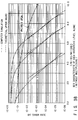
- FIG. 18 shows an error rate characteristic in simulating the decoding process by a computer on the assumption that there is no error propagation in the configuration of FIG. 17.
- a bit error rate (BER) is used as the error rate. Since three bits of information per modulation symbol are transmitted in decoding the data string at hierarchic level L1, when C/N is acceptable, the relationship between the BER and the symbol error rate of FIG.
- Curve [b] indicates theoretical values of the BER characteristic in 16-QAM transmission in uncoding
- curve [c] indicates theoretical values of the BER characteristic at hierarchic level L1
- curve [e] indicates theoretical values at hierarchic level L2.
- Curve [d], curve [f], and curve [g] indicate experimental values obtained by a computer simulation of the BER characteristic at hierarchic levels L1, L2, L3.
- curve [d] and curve [f] agree well with the theoretical values when the error rate is less than 10 ⁇ 5.
- Curve [a] is a theoretical BER curve for QPSK. Comparison of curve [a] with curve [g] shows that the characteristic is improved more than 8 dB in C/N in the range of BER ⁇ 10 ⁇ 5. In the range of BER ⁇ 10 ⁇ 3, errors in Viterbi decoding are dominant, so that the experimental characteristics disagree with the theoretical characteristics.
- FIGS. 19, 20, and 21 show actual weighting characteristics with a multiplexing ratio of 3000:2000:1000 symbols for hierarchic levels L1, L2, L3, by changing the size of dummy block.
- the abscissa indicates average C/N (Cav/N).
- the energy of the symbols in the first subset S3 of FIG. 5C is 2.5 times the average energy of FIGS. 5A and 5B. Taking this into account, the aforementioned [d] [f] [g] correspond to [d0] [f0] [g0] in FIG. 19, [d8] [f8] [g8] in FIG. 20, and [d32] [f32] [g32] in FIG. 21, respectively.
- the difference between hierarchic levels L2 and L3 become greater by 2.5 times the average energy. Since the energy of the received signal differs between hierarchic levels L1, L2, L3, it is correct for the weighting characteristic to have the abscissa indicating the average carrier power-to-noise power (Cav/N).
- FIG. 23 shows another embodiment of the signal mapping at hierarchic level L2.
- FIG. 24 shows an embodiment of the multilevel weighted transmission apparatus in using the signal mapping at hierarchic level L2 as shown in FIG. 23. Since in this embodiment, the signal mapping is common to S1, S2, S3, the configuration can be made simpler than those of the second and third embodiments shown in FIGS. 8, 9, and 10. Specifically, the outputs x3 and x2 of the multiplexer 21 are supplied as y3 and y2 to the signal mapping distributor 23. The output x1 of the multiplexer 21 is added with the frame information at the frame information adding circuit 263 and then is expanded at the convolutional coding unit 221, which then supplies the results as y1 and y0 to the signal mapping distributor 23.
- the Ie and Qe components outputted from the signal mapping distributor 23 are digitally modulated at the 16-QAM modulator 32, which outputs the modulated signals.
- FIG. 27 shows a configuration of the trellis decoder and its peripheral circuitry in the reception apparatus in a system where the frame information (multiplexing ratio information, frame synchronizing coding block, or dummy block) is added.
- the frame information is multiplexed to hierarchic level L3 whose error characteristic is the best (see the timing chart of FIG. 13), because it contains convolutional coding, the frame synchronization establishing process at the frame synchronizing circuit 461 and the sensing of multiplexing ratio information at the multiplexing ratio information sensing circuit 462 can be performed using Viterbi decoded bits.
- the period of dummy block modulation symbols in the first subset S3 in a one-bit per modulation symbol transmission are used.
- the Viterbi decoding process computation of branch metrics and path metrics or updating process of paths
- the setting of a suitable dummy block period allows errors to have completed propagating from hierarchic level L1 in the dummy block period. If the data string multiplexed in the dummy block period is dummy data, the dummy block data string contained in the Viterbi bits will not be used.
- the demultiplexer 45 will return the data string in the dummy block contained in the Viterbi decoding bits.
- FIG. 28 shows a transmission and a reception apparatus according to still another embodiment of the present invention.
- An FEC coding unit 27 is provided between the multiplexer 21 and the trellis coding unit 22.
- an FEC decoder 47 is provided between the trellis decoder 44 and the demultiplexer 45.
- a trellis coding/decoding unit is provided inside and an external FEC coding unit 27 and an external FEC decoder 47 are provided outside as shown in FIG. 28, thereby employing concatenated coding/decoding using RS (Reed-Solomin) coding/decoding suitable for burst errors.
- the external FEC coding unit 27 and the external FEC decoder 47 are common to three levels of hierarchy. The remaining portion is the same as the configuration of FIG. 3 and the same parts as those of FIG. 3 are indicated by the same reference symbols.
- FIG. 29 shows still another embodiment of the present invention.
- a trellis coding unit 22 and a trellis decoder 44 which perform internal FEC coding/decoding, operate in time division and are common to each level of hierarchy. Furthermore, an external FEC coding/decoding unit is provided for each level of hierarchy. This is effective in making larger the difference in the characteristic between transmission channels for the individual hierarchic levels.
- external FEC coding units 27a, 27b, 27c are provided between the information source signal coding unit 11 and the individual input terminals (1), (2), (3) of the multiplexer 21.
- external FEC decoders 47a, 47b, 47c are provided between the individual output terminals (1), (2), (3) of the demultiplexer 45 and the information source signal decoding unit 61. The remaining portion has the same configuration as that of FIG. 3.
- FIGS. 30 and 31 show a transmission and a reception apparatus according to still another embodiment of the present invention.
- FIG. 30 shows the configuration of part of a multilevel weighted transmission apparatus where the frame information (information on the multiplexing ratio, frame synchronizing code, or preamble) is added when FEC coding is effected by concatenated coding using internal FEC coding and external FEC coding.
- FIG. 31 shows a corresponding multilevel weighted reception apparatus.
- a multiplexing ratio information adding circuit 36 In the transmission apparatus, a multiplexing ratio information adding circuit 36, an external FEC coding unit 27, a frame synchronizing code adding circuit 37, and a trellis coding unit 38 are provided in that order on the output side of the multiplexer 21. The timing at each section is controlled by the first control circuit 26.
- the output of the multiplexer 43 is inputted to a trellis decoder 54 (internal FEC encoder).
- the output of the decoder 54 is inputted to an external FEC decoder 47.
- the output of the decoder 47 is inputted to a demultiplexer 45.
- the output of the trellis decoder 54 is also supplied to a frame synchronizing code sensing circuit 461.
- the output of the external FEC decoder 47 is also supplied to a multiplexing ratio information sensing circuit 462.
- the outputs of these sensing circuits 461, 462 are inputted to a timing control circuit 463.
- RS codes are used in external FEC coding.
- the addition of the multiplexing ratio information is effected at the stage before external FEC coding and the addition of frame synchronizing codes is effected after external FEC coding and before internal FEC coding.
- the addition of dummy blocks can be effected either before or after external FEC coding, provided that it is before internal FEC coding (trellis coding).
- the data string after the internal FEC decoding is introduced into the frame synchronizing circuit 461 to establish a frame synchronization and thereafter the output data string after the external FEC decoding is used to sense the multiplexing ratio information.
- the output signals ts3 and ts4 from the timing control circuit 43 are used to control the decoding timing for each of the internal FEC decoder (trellis decoder) 54 and the external FEC decoder 47.
- the frame period is an integral multiple of the period of one block of external FEC coding data.
- interleaving may be done after external FEC coding and deinterleaving may be done before external FEC decoding.
- interleaving is effected after trellis coding and deinterleaving is effected before trellis decoding to make burst errors on the transmission channel random.
- FIG. 32 shows still another embodiment of the present invention.
- each level of hierarchy is provided with digital modulators 25a, 25b, 25c and digital modulators 41a, 41b, 41c.
- the output of a first signal mapping distributor 23a is supplied to the first digital modulator 25a; the output of a second signal mapping distributor 23b is supplied to the first digital modulator 25b; and the output of a third signal mapping distributor 23c is supplied to the third digital modulator 25c.
- the outputs of the digital modulators 25a, 25b, 25c are supplied to an adder 28.
- the received signal is supplied to a first, second, and third digital demodulators 41a, 41b, 41c.
- the demodulated output of the first digital demodulator 41a is supplied to a first signal mapping demodulator 42a; the demodulated output of the second digital demodulator 41b is supplied to a second signal mapping demodulator 42b; and the demodulated output of the third digital demodulator 41c is supplied to a third signal mapping demodulator 42c.
- the remaining portion is the same as that of FIG. 3.
- the digital modulator/demodulator is shared by the individual levels of hierarchy and used in time division. Therefore, the quality of carrier reproduction and clock reproduction is limited by the hierarchic level whose transmission error rate is the worst, so that a very high-performance digital demodulator is needed.
- pilot carrier is transmitted separately as in the VSB-AM scheme (see "NCTA TECHNICAL PAPERS,” pp. 271-279, 1993)
- clock reproduction may be simplified by transmitting the symbol clock with another carrier.
- the present embodiment is characterized by requiring no high-performance powerful digital modulator even if the symbol clock is not transferred with another carrier.
- the carrier and clock reproduced at the low priority level digital modulator are used as the carrier and clock for a higher-level digital modulator.
- the ratio of the first, second, and third digital modulation carrier frequencies f1, f2, f3 is 3:2:1, a simple integral ratio
- PLL phase lock loop
- f1 can be obtained by bisecting fc and f2 can be obtained by trisecting fc.
- the clock reproduced at the third digital modulator 41c can be used at the first and second digital modulators 41a, 41b.
- each of the first, second, and third digital modulators 41a, 41b, 41c contains a speed change function controlled by the first control circuit so that the individual hierarchic levels may be consecutive according to the multiplexing ratio of the hierarchic levels and therefore the transmission frequency band may be the minimum.
- the timing is shown in FIG. 33A.
- FIG. 33B shows a spectrum of hierarchic levels L1, L2, L3.
- the symbol clock of digital modulation at the individual levels of hierarchy is controlled according to the multiplexing ratio so that the symbol clock may be consecutive at hierarchic levels L1, L2, L3.
- the reconstructed clock in least level (highest prior) layer can be reproduced using the clock reproduced at the low priority level on the decoding side.
- the second multiplexer 43 time-division multiplexes the signals of the individual hierarchic levels to effect trellis decoding of these outputs.
- the speed conversion on the transmission side may be performed by the respective mapping distributors 23a, 23b, 23c.
- digital modulators and demodulators as there are hierarchic levels are provided. Since this approach works as long as the carrier reproduction is independent from clock reproduction at the low priority level, for example, digital modulators and demodulators may be provided for two levels of hierarchy and those at hierarchic level L1 may be shared. That is, for example, the first and second digital modulators 25a, 25b may be grouped into one modulator and operated in time-division. Furthermore, the first and second digital demodulators 41a, 41b may be grouped into one demodulator and operated in time-division.
- FIG. 34 shows another embodiment of the present invention.
- the OFDM (orthogonal frequency division multiplexing) modulation scheme is used in digital modulation.
- a multilevel weighted transmission scheme suitable for multipath can be realized.
- the output of the multiplexing 24 is supplied to a serial-parallel converter 34.
- the output of the converter 34 is supplied to an OFDM modulator 35.
- the received signal is inputted to an OFDM demodulator 52.
- the modulated output of the modulator 52 is inputted to a parallel-serial converter 53.
- the Id and Qd from the converter 53 are supplied to the first to third signal mapping demodulators 42a, 42b, 42c. The remaining portion is the same as that of FIG. 3.
- the OFDM modulator 35 Generally, in the OFDM modulator 35, a certain number of symbols are grouped into one frame. On the reception side, by sensing the null symbol and reference symbol inserted on the transmission side, the frame synchronization for the reception apparatus is established. Thus, framing is done in advance in OFDM modulation and demodulation, so that by forcing the synchronization of time-division multiplexing at each hierarchic level to coincide with the frame synchronization, it is not necessary establish frame synchronization again at the second control circuit 46.
- timing control of time-division multiplexing and demultiplexing can be performed by using the frame synchronizing signal established at the OFDM modulator 52.
- the frame synchronizing signal obtained at the OFDM modulator 52 can be introduced into the second control circuit 46.
- FIG. 35 shows an example of the convolutional coding unit and FIG. 36 is a timing chart to help explain the operation of the coding unit.
- error propagation can be prevented by transmitting at least dummy blocks of symbols (the number corresponding to the constraint length of convolutional coding - 1) and .
- FIG. 35 shows an example of a feed-forward convolutional coding unit.
- FIG. 36 is a timing chart to help explain the operation of the convolutional coding unit of FIG. 35.
- the dummy block determined in the transmission and reception of six symbols is added to the input of one frame in the trellis coding unit at hierarchic levels L1, L2, L3. Only six symbols (the number corresponding to the constraint length in convolutional coding, 7 -1) are obtained for the dummy block.
- the problem is how to establish frame synchronization. If the digital modulation scheme is an OFDM modulation scheme as in the embodiment of FIG. 34, frame synchronization can be established by the OFDM modulator 52. Using the frame pulse obtained from the modulator 52, the second control circuit 46 controls the timing of the dummy block inserted on the reception side.
- the remaining dummy block is inserted into the rear end of each frame of time-division multiplexing signal, that is, nf times.
- FIG. 37 shows still another embodiment of the present invention.
- the digital modulation scheme is QPSK.
- a first puncture circuit 31a has a coding rate of 3/4 and generates eight bits of data for four QPSK modulation symbols, using the four-bit input convolutionally coded.
- a second puncture circuit 31b has a coding rate of 2/3 and generates six bits of data for three QPSK modulation symbols, using the four-bit input convolutionally coded.
- a first depuncture circuit 48a On the reception side, a first depuncture circuit 48a generates a branch metric for 12 bits of convolutional coding (six symbols) from four QPSK modulation symbols.
- a second depuncture circuit 48b generates a branch metric for 8 bits of convolutional coding (four symbols) from three QPSK modulation symbols.
- the original code is the same, the Viterbi decoding section excluding BMU can be shared.
- codes whose constraint length is the same and whose coding rate differ from each other may be time-division multiplexed in ascending order of the quality of transmission error characteristic.
- codes whose constraint length is the same and whose coding rate differ from each other may be time-division multiplexed in ascending order of the quality of transmission error characteristic.
- the individual codes thus obtained have the same constraint length, so that in a decoding process, they can share the Viterbi decoding section excluding BMU.
- L3 is for a coding rate of 1/2.
- the dotted lines indicate theoretical boundary values. This has been disclosed in reference: Yasuda, Hirata, and Ogawa, "Easy, High-coding Rate Convolutional codes in Viterbi Decoding and its Characteristics," --- (B), vol. J64-B, No. 7, pp. 573-580, Jul. 1981.
- the abscissa is converted into C/N (precisely, Es/No) for the purpose of making the difference in weighting distinctive.
- FIGS. 39 and 40 show the characteristics of transmission error rate in a transmission and reception system in a case where one frame is formed with 98 bits for L1, 102 bits for L2, and 308 bits for L3 and is then multiplexed. In an example of transmission, there is no dummy block. Explanation of transmission characteristic has been given in FIGS. 12A and 12B.
- FIG. 39 shows a characteristic in the case where the order of multiplexing is descending order of the quality of transmission error characteristic (L3, L2, L1, L3, L2, ).
- FIG. 40 shows a characteristic in the case where the order of multiplexing is ascending order of the quality of transmission error characteristic (L1, L2, L3, L1, L2, ).
- L1 is influenced by error propagation in L3
- L2 is influenced by error propagation in L1
- L3 is influenced by error propagation in L2, so that the characteristic is poorer than the theoretical values.
- the characteristic of FIG. 40 shows that L3 is influenced only by error propagation in L1 and the characteristics of L1 and L2 of FIG. 40 are closer to the theoretical values than the characteristics of L1 and L2 of FIG. 39.
- the characteristic of L3 of FIG. 39 is better than that of FIG. 40.
- L3 is influenced by error propagation in L2
- L3 is influenced by error propagation in L1
- L1 has a poorer transmission characteristic than L2.
- FIG. 41 shows a characteristic in a case where transmission is carried out with a dummy block added. Specifically, FIG. 41 shows the characteristic of transmission error rate in a transmission and reception system in a case where one frame is formed with 96 bits for dummy block Ds, 98 bits for L1, 102 bits for L2, and 308 bits for L3 and is then multiplexed. The order of transmission is ascending order of the quality of transmission error rate (L1, L2, L3, D, L1, L2, L3, D, ...) and dummy block D is contained.
- feed-forward convolutional coding is used, so that the actually transmitted dummy block contains six bits. For example, six bits of "0" is subjected to convolutional coding and coded symbols for six symbols are transmitted.
- a branch metric corresponding to the remaining (96 - 6) 90 symbols is added to a branch metric for six symbols obtained from the received signal through computation and then Viterbi decoding of the received signal is started.
- the added branch metric corresponds to coded bit (0 0).
- important data such as scale factors may be transmitted in a hierarchic level whose error characteristic is good, and the other data (A) may be transmitted in a hierarchic level whose error characteristic is poorer.
- transmission may be carried out in such a manner that
- the scale factor is needed first of all. In this case, to get the scale factor, A may be replaced with S before decoding and S is decoded earlier or the operation may proceed one frame ahead and S be transmitted.
- the number of error correction encoders can be reduced to one without introducing error propagation in convolutional coding.
- first subsets when modulation symbols constituting a constellation for digital modulation is divided into subsets (hereinafter, referred to first subsets), it is possible to make the transmission error characteristic different (weight the transmission error characteristic) by making different the minimum Euclidean distance between subset symbols in the trellis-coded modulation scheme contained in each subset.
- each subset can be divided into subsets as shown in FIGS. 5A, 5B, and 5C.
- 16 modulation symbols (one symbol: y3 y2 y1 y0) of FIG. 15A are used for transmission of the data string at hierarchic level L1 of the transmission channel; eight modulation symbols (one symbol: y2 y1 y0) of FIG. 5B are used for transmission of the data string at hierarchic level L2; and four modulation symbols (one symbol: y1 y0) of FIG. 5C are used for transmission of the data string at hierarchic level L3.
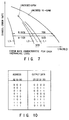
- the transmission error characteristic depends on the configuration of the coding unit. For example, as shown in FIG. 7, the transmission error characteristic is 8 to 9 dB better in C/N than the characteristic of uncoding QPSK.
- a multilevel weighted transmission and reception apparatus with an improved transmission error characteristic can be realized by effecting a pair of trellis coding and decoding at the trellis coding unit 22 and trellis decoder 44.
- this helps reduce the size of the apparatus. This is because the convolutional coding process of each level of hierarchy shares the trellis coding unit and the trellis decoder is also shared by the individual hierarchic levels.
- the first control circuit 26 and the second control circuit 46 of FIG. 3 time-division multiplexes hierarchic levels L1, L2, ..., Ln serving as n transmission channels in ascending order of the quality of transmission error characteristic (i.e., hierarchic levels L1, L2, ..., Ln).
- the reason for this is that when convolutional coding/decoding of each hierarchic level is divided with respect to time as shown in FIG. 12A and coding and decoding is effected serially, if transmission is started, beginning at the hierarchic level with the best transmission error characteristic toward that with a poorer characteristic, error propagation will take place in decoding.
- the reason why the error propagation takes place is that the decoding process is carried out using the continuity of the distance between codes.
- the data string at hierarchic level L1 of the transmission channel is ⁇ Le1, Ie1, Qe1, Id1, Qd1, Ld1 ⁇ .
- the data string at hierarchic level L2 of the transmission channel is ⁇ Le2, Ie2, Qe2, Id2, Qd2, Ld2 ⁇ .
- the error propagation is prevented by adding a dummy block (dummy data or data with a poor error characteristic, such as part of the data in hierarchic level L1) to the rear end of the data string in the hierarchic level Li.
- a dummy block dummy data or data with a poor error characteristic, such as part of the data in hierarchic level L1
- error propagation extends over at least as many symbols as there are in the restraint length in convolutional coding.
- a dummy block for at least as many symbols as correspond to the restraint length is added.
- a dummy block of the symbol component corresponding to the length of path i.e., four to six times the computation window, normally the restraint length in Viterbi decoding
- the dummy block is processed.
- the decoded symbols corresponding to the dummy block contain error propagation, the error propagation is completed in the period of the dummy block by providing a sufficient number of symbols for the dummy block.
- more reliable transmission and reception can be performed by transferring information on the multiplexing ratio in time-division multiplexing at each hierarchic level through hierarchic level Ln whose transmission error characteristic is the best.
- a frame synchronizing code is added in the period that n hierarchic levels of the transmission channel make a round, that is, the frame period at hierarchic level Ln whose transmission error characteristic is the best, and on the reception side, frame synchronization can be established using the frame synchronizing code.
- FIG. 13 shows its transmission timing.
- a frame synchronizing circuit 461 establishes frame synchronization
- a multiplexing ratio information sensing circuit 462 senses the multiplexing ratio information
- a timing control circuit 463 controls time-division multiplexing. Since decoding of convolutional codes (Viterbi decoding) does not contain the concept of blocks, the decoding process can be carried out before frame synchronization has been established (symbol synchronization has only to be established).
- frame synchronization is added to the data string before trellis coding as shown in FIGS. 14 and 15 so that frame synchronization can be established using the data string after trellis decoding (after Viterbi decoding). Then, the effect of error correction can lend itself to establishing frame synchronization, with the result that frame synchronization can be established reliably.
- the frame information adding circuit 263 may be provided at the input of any stage before the multiplexer 21 (represented by dotted lines in FIG. 14).
- a third digital modulator 25c and a third digital modulator 41c are a modulator and a demodulator for QPSK data, where carrier reproduction and clock reproduction are easier and more reliable than those of higher-order multilevel 8-QAM and 16-QAM. Therefore, by setting the center frequencies f1, f2, and f3 of the digital modulation signals of the first, second, third digital modulators 25a, 25b, 25c at a simple integer ratio, the remaining f1 and f2 can be reproduced using carrier f3 reproduced at the third digital modulator 41c, which is simpler and more reliable than the first and second digital modulators 41a, 41b reproduce carries independently.
- the clocks for the input data strings in the first, second, and third digital modulators 25a, 25b, 25c are in synchronization, the clocks for the data strings Id1, Qd1, and Id2, Qd2 can be reproduced using the clock reproduced at the third digital modulator 41c, which is simpler and more reliable than the first and second digital modulators 41a, 41b reproduce carries independently.
Applications Claiming Priority (2)
| Application Number | Priority Date | Filing Date | Title |
|---|---|---|---|
| JP6178608A JPH0846655A (ja) | 1994-07-29 | 1994-07-29 | 重み付け伝送方式及びその装置 |
| JP178608/94 | 1994-07-29 |
Publications (1)
| Publication Number | Publication Date |
|---|---|
| EP0702476A2 true EP0702476A2 (fr) | 1996-03-20 |
Family
ID=16051433
Family Applications (1)
| Application Number | Title | Priority Date | Filing Date |
|---|---|---|---|
| EP95111926A Withdrawn EP0702476A2 (fr) | 1994-07-29 | 1995-07-28 | Procédé de transmission multiple des niveaux pondéré et appareil de transmission et réception pour la transmission multiple des niveaux pondéré |
Country Status (4)
| Country | Link |
|---|---|
| EP (1) | EP0702476A2 (fr) |
| JP (1) | JPH0846655A (fr) |
| KR (1) | KR960006306A (fr) |
| CA (1) | CA2154848A1 (fr) |
Cited By (9)
| Publication number | Priority date | Publication date | Assignee | Title |
|---|---|---|---|---|
| EP0674413A2 (fr) * | 1994-03-21 | 1995-09-27 | AT&T Corp. | Arrangement de multiplexage en temps de constellations de signaux |
| EP0933896A2 (fr) * | 1998-01-28 | 1999-08-04 | Nec Corporation | Circuit démodulateur avec correction d'erreur |
| EP1075088A2 (fr) * | 1999-08-02 | 2001-02-07 | Sony Corporation | Dispositif de codage, procédé de codage et support associé |
| WO2002023738A3 (fr) * | 2000-09-12 | 2003-05-08 | Broadcom Corp | Code concatene parallele utilise avec un turbo decodeur interactif a entree et sortie souples (siso) |
| WO2006000941A1 (fr) | 2004-06-21 | 2006-01-05 | Koninklijke Philips Electronics N.V. | Modulation de flux de donnees avec mappage de sous-ensembles d'une constellation |
| EP2347514A1 (fr) * | 2008-09-12 | 2011-07-27 | Sharp Kabushiki Kaisha | Systèmes et procédés pour réaliser une protection inégale contre les erreurs au moyen d'un codage en emboîtement |
| US8238416B2 (en) | 2006-01-17 | 2012-08-07 | Samsung Electronics Co., Ltd. | Apparatuses and methods for transmitting and receiving uncompressed AV data |
| EP3550728A4 (fr) * | 2017-02-22 | 2020-07-15 | NTT Electronics Corporation | Dispositif de correction d'erreur, procédé de correction d'erreur et dispositif de communication |
| CN112567463A (zh) * | 2018-08-21 | 2021-03-26 | 美光科技公司 | 用于多电平信令的预失真 |
Families Citing this family (4)
| Publication number | Priority date | Publication date | Assignee | Title |
|---|---|---|---|---|
| US6744822B1 (en) * | 2000-08-14 | 2004-06-01 | Koninklijke Philips Electronics N.V. | FEC scheme for encoding two bit-streams |
| JP4765227B2 (ja) * | 2001-08-21 | 2011-09-07 | 富士通株式会社 | Ofdm受信装置 |
| JP3845822B2 (ja) * | 2003-01-23 | 2006-11-15 | ソニー・エリクソン・モバイルコミュニケーションズ株式会社 | データ受信方法及び装置 |
| CN102148797B (zh) * | 2010-02-08 | 2014-02-12 | 上海贝尔股份有限公司 | 合并的多数据流的传输技术 |
-
1994
- 1994-07-29 JP JP6178608A patent/JPH0846655A/ja active Pending
-
1995
- 1995-07-27 CA CA002154848A patent/CA2154848A1/fr not_active Abandoned
- 1995-07-28 EP EP95111926A patent/EP0702476A2/fr not_active Withdrawn
- 1995-07-29 KR KR1019950023051A patent/KR960006306A/ko not_active Application Discontinuation
Cited By (16)
| Publication number | Priority date | Publication date | Assignee | Title |
|---|---|---|---|---|
| EP0674413A3 (fr) * | 1994-03-21 | 1997-05-07 | At & T Corp | Arrangement de multiplexage en temps de constellations de signaux. |
| EP0674413A2 (fr) * | 1994-03-21 | 1995-09-27 | AT&T Corp. | Arrangement de multiplexage en temps de constellations de signaux |
| EP0933896A2 (fr) * | 1998-01-28 | 1999-08-04 | Nec Corporation | Circuit démodulateur avec correction d'erreur |
| EP0933896A3 (fr) * | 1998-01-28 | 2001-10-17 | Nec Corporation | Circuit démodulateur avec correction d'erreur |
| EP1075088A3 (fr) * | 1999-08-02 | 2003-05-14 | Sony Corporation | Dispositif de codage, procédé de codage et support associé |
| EP1075088A2 (fr) * | 1999-08-02 | 2001-02-07 | Sony Corporation | Dispositif de codage, procédé de codage et support associé |
| US7035342B2 (en) | 2000-09-12 | 2006-04-25 | Broadcom Corporation | Parallel concatenated code with soft-in soft-out interactive turbo decoder |
| WO2002023738A3 (fr) * | 2000-09-12 | 2003-05-08 | Broadcom Corp | Code concatene parallele utilise avec un turbo decodeur interactif a entree et sortie souples (siso) |
| US7460608B2 (en) | 2000-09-12 | 2008-12-02 | Broadcom Corporation | Parallel concatenated code with soft-in soft-out interactive turbo decoder |
| US7570700B2 (en) | 2000-09-12 | 2009-08-04 | Broadcom Corporation | Parallel concatenated code with soft-in soft-out interactive turbo decoder |
| WO2006000941A1 (fr) | 2004-06-21 | 2006-01-05 | Koninklijke Philips Electronics N.V. | Modulation de flux de donnees avec mappage de sous-ensembles d'une constellation |
| US8238416B2 (en) | 2006-01-17 | 2012-08-07 | Samsung Electronics Co., Ltd. | Apparatuses and methods for transmitting and receiving uncompressed AV data |
| EP2347514A1 (fr) * | 2008-09-12 | 2011-07-27 | Sharp Kabushiki Kaisha | Systèmes et procédés pour réaliser une protection inégale contre les erreurs au moyen d'un codage en emboîtement |
| EP2347514A4 (fr) * | 2008-09-12 | 2012-09-12 | Sharp Kk | Systèmes et procédés pour réaliser une protection inégale contre les erreurs au moyen d'un codage en emboîtement |
| EP3550728A4 (fr) * | 2017-02-22 | 2020-07-15 | NTT Electronics Corporation | Dispositif de correction d'erreur, procédé de correction d'erreur et dispositif de communication |
| CN112567463A (zh) * | 2018-08-21 | 2021-03-26 | 美光科技公司 | 用于多电平信令的预失真 |
Also Published As
| Publication number | Publication date |
|---|---|
| KR960006306A (ko) | 1996-02-23 |
| JPH0846655A (ja) | 1996-02-16 |
| CA2154848A1 (fr) | 1996-01-30 |
Similar Documents
| Publication | Publication Date | Title |
|---|---|---|
| US6917655B2 (en) | Coding and decoding a signal modified in accordance with the feedback states of an encoder | |
| KR100247373B1 (ko) | 신호 송신 장치, 신호 수신 장치, 및 신호 송수신방법 | |
| US7570697B2 (en) | Advanced MIMO interleaving | |
| CN100527834C (zh) | 处理补充数据的电视传输和接收系统及其方法 | |
| US5416801A (en) | Digital signal transmission system based on partitioning of a coded modulation with concatenated codings | |
| AU2002301551B2 (en) | Apparatus and method for performing coding and rate matching in a CDMA mobile communication system | |
| US5394439A (en) | Bisdn compatible modem codec for digital information communication system | |
| US6687310B1 (en) | Trellis coded modulation system for digital television signal with trellis coded data and synchronization symbols | |
| US9628867B2 (en) | Method and apparatus for data rate controller for a code block multiplexing scheme | |
| EP0702476A2 (fr) | Procédé de transmission multiple des niveaux pondéré et appareil de transmission et réception pour la transmission multiple des niveaux pondéré | |
| US5729526A (en) | Asynchronous transfer mode type multimedia radiocommunication system | |
| JPH10504689A (ja) | デジタルテレビジョン信号のためのデータフレーム構造および同期システム | |
| JPH07170305A (ja) | 送信器および受信器 | |
| JP2002190756A (ja) | 等化器 | |
| EP0827309B1 (fr) | Modulation codée avec codage en répétition et en arbre | |
| US6608870B1 (en) | Data frame for 8 MHZ channels | |
| EP1065790B1 (fr) | Système de modulation codée en treillis | |
| US20110258669A1 (en) | System and method for multi-carrier multiplexing | |
| US6532267B1 (en) | Variable rate constellation precoding | |
| US5982818A (en) | Method for implementing trellis codes for ISI channels | |
| JPH07143185A (ja) | 重み付け伝送方式及びその装置 | |
| US7107513B1 (en) | Method and apparatus for decoding received data in a communications system | |
| JP3691211B2 (ja) | デジタル信号送信装置、およびデジタル信号受信装置 | |
| JPH10322388A (ja) | デジタル信号伝送方法、およびデジタル信号伝送装置 | |
| WO2000074375A1 (fr) | Systeme de television numerique pour canaux 8 mhz |
Legal Events
| Date | Code | Title | Description |
|---|---|---|---|
| PUAI | Public reference made under article 153(3) epc to a published international application that has entered the european phase |
Free format text: ORIGINAL CODE: 0009012 |
|
| 17P | Request for examination filed |
Effective date: 19950825 |
|
| AK | Designated contracting states |
Kind code of ref document: A2 Designated state(s): DE FR GB NL |
|
| STAA | Information on the status of an ep patent application or granted ep patent |
Free format text: STATUS: THE APPLICATION HAS BEEN WITHDRAWN |
|
| 18W | Application withdrawn |
Withdrawal date: 19970624 |