EP0701928B1 - Prüfung eines Gassackzündpillewiderstandes - Google Patents
Prüfung eines Gassackzündpillewiderstandes Download PDFInfo
- Publication number
- EP0701928B1 EP0701928B1 EP95305538A EP95305538A EP0701928B1 EP 0701928 B1 EP0701928 B1 EP 0701928B1 EP 95305538 A EP95305538 A EP 95305538A EP 95305538 A EP95305538 A EP 95305538A EP 0701928 B1 EP0701928 B1 EP 0701928B1
- Authority
- EP
- European Patent Office
- Prior art keywords
- resistor
- airbag
- voltage
- resistance
- squib
- Prior art date
- Legal status (The legal status is an assumption and is not a legal conclusion. Google has not performed a legal analysis and makes no representation as to the accuracy of the status listed.)
- Expired - Lifetime
Links
Images


Classifications
-
- B—PERFORMING OPERATIONS; TRANSPORTING
- B60—VEHICLES IN GENERAL
- B60R—VEHICLES, VEHICLE FITTINGS, OR VEHICLE PARTS, NOT OTHERWISE PROVIDED FOR
- B60R21/00—Arrangements or fittings on vehicles for protecting or preventing injuries to occupants or pedestrians in case of accidents or other traffic risks
- B60R21/01—Electrical circuits for triggering passive safety arrangements, e.g. airbags, safety belt tighteners, in case of vehicle accidents or impending vehicle accidents
- B60R21/017—Electrical circuits for triggering passive safety arrangements, e.g. airbags, safety belt tighteners, in case of vehicle accidents or impending vehicle accidents including arrangements for providing electric power to safety arrangements or their actuating means, e.g. to pyrotechnic fuses or electro-mechanic valves
- B60R21/0173—Diagnostic or recording means therefor
-
- G—PHYSICS
- G01—MEASURING; TESTING
- G01R—MEASURING ELECTRIC VARIABLES; MEASURING MAGNETIC VARIABLES
- G01R31/00—Arrangements for testing electric properties; Arrangements for locating electric faults; Arrangements for electrical testing characterised by what is being tested not provided for elsewhere
- G01R31/28—Testing of electronic circuits, e.g. by signal tracer
- G01R31/282—Testing of electronic circuits specially adapted for particular applications not provided for elsewhere
- G01R31/2829—Testing of circuits in sensor or actuator systems
Definitions
- the present invention relates generally to electronic testing systems and more particularly to an arrangement for testing the operability of a vehicle airbag system.
- Airbag systems utilised in vehicles typically utilise a resistor, known as an airbag squib resistor, as a trigger resistor to enable the airbag to be inflated when specified conditions are met.
- a resistor known as an airbag squib resistor
- To ensure timely inflation of the airbag it is helpful to periodically monitor the resistance of the airbag squib resistor during operation of the vehicle, Determining whether the resistance of the airbag squib resistor is within acceptable levels while the vehicle is in operation requires the airbag squib resistor to be tested in a manner which does not cause inflation of the airbag.
- the testing is further complicated by variations in the supply voltage and electrical noise while the vehicle is in operation and also by process variations which may occur in the manufacture of the circuitry of the airbag system.
- DE-U-8815200 and WO-A-92/09461 are concerned with ascertaining whether the resistance of an airbag resistance element is within allowable limits.
- the electric detonator (D) is arranged (with resistance Rv) in one branch of a resistance bridge (Rv,R 1 ,R 2 ,D) and the voltage drop across D is compared with a reference voltage which is generated by the voltage divider R 1 and R 2 .
- Rv resistance bridge
- WO-A-92/09461 another test circuit is described in which two triggering devices (10,11) are tested. Voltage comparators 24 and 25 are connected such that an error is indicated if the resistance of the devices is too great or too small.
- Resistors 26, 27 and 28 give two reference potentials.
- this object is achieved by the method of measuring the operability of an airbag squib resistive element as defined in independent claim 1 and the respective apparatus as defined in independent claim 6.
- Embodiments of the invention are disclosed in the dependent claims.
- the operability of an airbag squib resistive element is determined by measuring a first value indicative of the resistance of a first resistive element which has a resistance corresponding to a minimum acceptable resistance value for the airbag squib resistive element, and measuring a second value indicative of the resistance of a second resistive element which has a resistance corresponding to a maximum acceptable resistance value for the airbag squib resistive element.
- a third value indicative of the resistance of the airbag squib resistive element is then measured and is compared to the first value and to the second value.
- An airbag inoperative condition is set if the third value is not between the first value and the second value.
- An advantage of at least certain preferred embodiments is that the operability of the airbag squib resistor may be accurately verified during operation of the vehicle, without damaging the squib resistor if a short circuit occurs, and despite process variations in the fabrication of circuit components, or the presence of electrical noise or other physical effects present in vehicle electrical systems.
- Fig. 1 shows a preferred embodiment of an airbag squib testing circuit which is advantageously contained within a vehicle airbag system.
- a first current source 22 generates a current I 1 and a second current source 24 generates a current I 2 .
- second current source 24 produces a nominal current of 50 mA.
- First current source 22 produces nominally about four-thirds as much current as second current source 24, or approximately 65 mA. Therefore, with switches 16 and 18 closed, current I 2 which is nominally 50 mA flows through the series combination of R squib , R min and Rmax .
- First current source 22 is advantageously limited to prevent blowing resistors 10, 12 and 14 and to prevent excessive current flow in the event that a short circuit to ground is created.
- R min and R max are advantageously fixed value zero temperature coefficient resistors.
- R min advantageously has a resistance which is indicative of a minimum resistance value for R squib in order for it to operate properly in inflating the airbag.
- R max advantageously has a resistance which is indicative of a maximum resistance value for R squib in order for it to operate properly in inflating the airbag.
- R min has a nominal value of 1 ohm and R max has a nominal value of 3.5 ohms.
- Switches 16 and 18, which are coupled to I/O port 140 of ACU 100, operate under control of ACU 100 to control current flow through resistors R squib , R min and R max .
- Switches 16 and 18 are preferably implemented as field effect transistors (FETs) with a drain resistance while conducting of approximately 10 to 20 ohms or less.
- a switch 32 coupled to I/O port 140 of ACU 100, operates under control of ACU 100 to couple inputs 28 of a voltage-to-current (V-I) converter 26 across individually R squib , R min or R max .
- Switch 32 can be controlled by microprocessor 33 to be in a first state in which the inputs of switch 32 are decoupled from R squib , R min or R max , a second state in which the inputs of switch 32 are coupled to receive the voltage existing across R squib , a third state in which the inputs of switch 32 are coupled to receive the voltage existing across R min , and a fourth state in which the inputs of switch 32 are coupled to receive the voltage existing across R max .
- Switch 32 may take a variety of known forms and preferably takes the form of a solid state device.
- Voltage-to-current converter 26 operates under known methods to generate a current at its output 30 which is proportional to the voltage received at inputs 28.
- a switch 36 and a capacitor 38 are coupled in parallel to output 30 of V-I converter 26.
- Switch 36 which is coupled to I/O port 140 of ACU 100, operates under control of ACU 100 to initiate and control charging and discharging of capacitor 38.
- a comparator in the form of voltage comparator 42 has a non-inverting input coupled to the output 30 of V-I converter 26 and an inverting input coupled to a predetermined reference voltage V ref .
- Output 48 of voltage comparator 42 is coupled to an I/O port 140 of ACU 100. Voltage comparator 42 operates to generate a binary signal on output 48.
- Output 48 will be high if the voltage at the non- inverting input is greater than the voltage at the inverting input and output 48 will be low if the voltage drop at the non-inverting input is less then the voltage at the inverting input.
- voltage comparator 42 generates a logical "1" when the voltage across capacitor 38 exceeds predetermined threshold voltage V ref , and a logical "0" otherwise.
- Airbag Control Unit (ACU) 100 comprises a microcomputer including a central processor unit (CPU) 141, input and output (I/O) port 140, read only memory (ROM) 142 for storing control programs, random access memory (RAM) 143, for temporary data storage which may also be used for counters or timers, and a conventional data bus.
- ACU 100 operates under stored program control to receive input signals, and to generate output signals to control various operational and diagnostic aspects of the vehicle airbag system.
- Circuit 50 is used for a short-test of the squib resistor 10.
- Circuit 50 includes switches 52 and 53 controlled by ACU 100, and resistors 56 and 58 which form a voltage divider connected to a voltage source V d seen at 60.
- Resistors 56 and 58 are coupled at node 62 which is connected to the non-inverting terminal of an operational amplifier 64.
- the operational amplifiers output terminal is connected to its inverting terminal so that its output voltage is equal to the voltage at node 62, in order to perform a voltage follower function.
- Fig. 2 of the drawings shows the steps utilised in a preferred embodiment to determine whether the resistance of airbag squib resistor R squib is within a predetermined range.
- the steps shown in Fig. 2 are preferably implemented in the form of a stored program executed by ACU 100.
- the routine is entered at 201 and at 202 switches 16 and 18 are closed resulting in current I 2 flowing through the series combination of R squib , R min and R max .
- inputs 28 of V-I converter 26 are switched so as to receive the voltage across R squib .
- Inputs 28 of V-I converter 26 have a high input impedance so that the current flowing through R squib , R min or R max when the V-I converter is coupled across either resistor is substantially the same as current I 1 .
- current I 1 is limited by I 2 , thus the current flowing through R squib , R min or R max is substantially equal to current I 2 .
- switch 36 is opened and a time measurement, T squib is initiated preferably by starting the counting of a counter within ACU 100. As can be seen, the opening of switch 36 initiates charging of capacitor 38.
- the time measurement continues by periodically incrementing the counter within ACU 100, in response to a system clock contained within ACU 100, until the output 48 of voltage comparator 42 generates a logical "1" signal, which as explained above, occurs when the voltage across capacitor reaches a voltage greater than the predetermined threshold voltage V ref .
- the time measurement is stopped by disabling counting of the counter within ACU 100, the value T squib is stored by ACU 100 and switch 36 is closed to discharge capacitor 38. Steps 203 to 206 are repeated to generate a time measurement for T min corresponding to R min and a time measurement T max corresponding to R max .
- the order in which the time measurement for R squib , R min and R max is taken may be altered.
- the time measurement taken for voltage 42 to generate a logical "1" with switch 32 in each of its three positions can be used to determine whether the resistance of R squib is greater than the resistance of R min and less than the resistance of R max by comparing measured values T squib , T min and T max which represent values which are inversely proportional to the resistance of the corresponding resistor.
- T squib is compared to T min and T max . If T squib is less than T min and greater than T max , then the resistance of R squib is determined to be within an acceptable range, and the routine is ended at 210. Otherwise, an R squib inoperative condition within ACU 100 is set at 209 and the routine is ended. In a preferred embodiment, the setting of the R squib inoperative condition results in an indication to the vehicle operator that the airbag system is not operating properly.
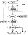
- Fig. 3 shows the steps conducted by ACU 100 to determine whether or not R squib is shorted to ground.
- Switches 52 and 53 are normally in an open position. In such a position, output voltage V a of the operational amplifier 64 has a quiescent value V q determined by resistors 56 and 58 and voltage V D .
- squib resistor 10 normally is floating, that is, none of its terminals is connected directly or indirectly to ground.
- switches 16 and 18 are opened, and at 303, switch 52 is closed to test whether the upper terminal of squib resistor 10 is shorted.
- V a is converted to a digital value by analogue-to-digital (A/D) converter 79 received by ACU 100 through I/O port 140 and compared to a stored digitally expressed value corresponding to V q .
- A/D analogue-to-digital
- V a may vary over a predetermined range and be considered equal to V q . Such a feature allows for minor variations in V q due to environmental factors or process variations.
- switch 52 is opened and switch 53 is closed to perform a similar test, at steps 306-309, on the lower terminal, seen at 12, of R squib .
- Fig. 4 shows an alternative embodiment in which the airbag system includes a plurality or airbag squib resistors and a mechanism for testing operability of each of the airbag squib resistors.
- Fig. 4 shows an apparatus for testing N airbag squib resistors, where N is an integer.
- the mechanism of fig. 1 has been modified to include additional switching devices.
- Components in Fig. 4 labelled 18, 28, 30, 12, 14, 24, 50, and 52 are identical in kind to the same referenced components in Fig. 1.
- Explicitly shown in Fig. 4 are three squib resistors labelled R 1 , R 2 , and R N which collectively comprise a total of N squib resistors.
- Each one of the devices labelled 701 through 70 N serves the combined functions of a switch and a current limited pull-up. Each such device is preferably a PMOS FET with a properly biased gate.
- devices 70 1 , through 70 N may take the form of a single current source with N switches, each corresponding to a squib resistor R 1 through R N . There are N such devices, with three being explicitly shown.
- Switches labelled 18 1 to 18 N each corresponding to one of the squib resistors R 1 to R N .
- Each of the switches 18 operate to couple the corresponding squib resistor in series with resistors R min and R max .
- Each squib resistor additionally has two corresponding switches labelled 52 1 to 52 2N which operate to individually couple each of the two terminals of the corresponding squib resistor to short-test circuitry 50.
- Switch 76 is similar to 32 of Fig. 1 in that inputs 28 and 30 may be connected across each one of the plurality of squib resistors via N positions A 1 , A 2 , . . ., A N .
- switches 52 are placed in an open state.
- switches 18 which is connected directly to R 2 is placed in closed state and the rest are turned off.
- Devices 70 are turned off except for device 70 2 which is connected directly to R 2 and is energised.
- Switch 76 connects inputs 28 to position A 2 . The rest of the steps follow that of the discussion for Fig. 1.
- devices 70 and switches 18 are placed in an open state. Among switches 52, only those two directly connected to R 2 are to be turned on, but only one at a time. The rest of the steps follow that of the discussion for Fig. 1.
- ACU 100 With the exception of ACU 100, the apparatus shown in figs. 1 and 4 are preferably contained on a single integrated circuit. Alternatively, all of the components including ACU 100 shown may be integrated onto a single integrated circuit.
- the system described herein provides numerous advantages.
- the squib resistor being measured or tested need not be disconnected from the airbag circuit during testing. At all times during the measurement of the squib resistor, the current flowing through the squib resistor is kept low so as not to inadvertently detonate the airbag controlled by the squib resistor.
- measuring the resistance of the squib resistor by measuring time intervals required for charging the capacitor from zero voltage to the reference voltage as previously discussed provides good noise immunity because of the integration functions performed by the capacitor.
- the testing system described allows for greater process variation in device fabrication.
Claims (15)
- Ein Verfahren zur Messung der Funktionsfähigkeit eines als Airbag-Zündwiderstand dienenden, in das Airbagsystem eines Fahrzeug eingebauten Bauelements, und die periodische Durchführung dieses Verfahrens während des Betriebs des Fahrzeuges, um festzustellen, ob der elektrische Widerstand des als Zündwiderstand dienenden Bauteils nicht zwischen einem ersten Wert und einem zweiten Wert liegt, und einen Zustand zu schalten, der die Funktionsunfähigkeit des Airbags anzeigt, wenn der elektrische Widerstand nicht zwischen diesem ersten Wert und diesem zweiten Wert liegt, gekennzeichnet durch die Bereitstellung eines ersten Widerstandsbauteils, das einem für diesen Airbag-Zündwiderstand minimal zulässigen elektrischen Widerstandswert entspricht; eines zweiten Widerstandsbauteils, das einem für diesen Airbag-Zündwiderstand maximal zulässigen elektrischen Widerstandswert entspricht; und des Airbag-Zündwiderstandbauteils, wobei all diese Widerstandsbauteile in Reihe geschaltet sind; und das ferner durch die Messung dieses für den Widerstand dieses ersten Widerstandsbauteils indikativen Werts sowie durch die Messung dieses für den Widerstand dieses zweiten Widerstandsbauteils indikativen Werts, die Messung eines für den Widerstand dieses Airbag-Zündwiderstandbauteils indikativen, dritten Wertes, und den Vergleich dieses dritten Wertes mit diesem ersten Wert und diesem zweiten Wert gekennzeichnet ist.
- Ein Verfahren nach Anspruch 1, in dem die Schritte zur Messung des ersten Wertes, des zweiten Wertes und des dritten Wertes jeweils die folgenden Schritte umfassen:Verschalten der Serienschaltung aus diesem ersten Widerstandsbauteil, diesem zweiten Widerstandsbauteil und diesem Widerstandsbauteil zur Airbagzündung mit einer Stromquelle, und zur Bestimmung des zu messenden Wertes,Ermitteln des jeweiligen Spannungsabfalls über die einzelnen Widerstandselemente,Erzeugen eines Stromes, der proportional zu diesem ermittelten Spannungsabfall ist,Laden eines Kondensator mit diesem Strom,Messen der Zeit, die benötigt wird, um diesen Kondensator bis zu einer vorbestimmten Spannung aufzuladen, undBestimmen des Wertes als Funktion dieser gemessenen Zeit.
- Ein Verfahren nach Anspruch 2, in dem der Schritt der Messung der zum Laden dieses Kondensators auf eine vorbestimmte Spannung benötigten Zeit aus folgenden Schritten besteht:Starten des Zählvorgangs an einem digitalen Zähler mit dem Beginn des Ladevorgangs dieses Kondensators;Stoppen des Zählvorgangs dieses digitalen Zählers, wenn die Spannung über diesen Kondensator diese vorbestimmte Spannung erreicht hat; undBestimmen dieser gemessenen Zeit als Funktion des Zustandes dieses digitalen Zählers.
- Ein Verfahren nach Anspruch 3, in dem das erste Widerstandsbauteil, das zweite Widerstandsbauteil und das Widerstandsbauteil zur Airbagzündung durch mehrere monolithische Schalter in Serie verbunden sind.
- Ein Verfahren nach irgendeinem der vorhergehenden Ansprüche, in dem das Widerstandsbauteil zur Zündung des Airbags zwei Anschlußpunkte umfaßt, und in dem das Verfahren die zusätzlichen Schritte enthält, worin jeder Anschlußpunkt dieses Widerstandsbauteil zur Zündung des Airbags auf einen Kurzschluß geprüft wird und ein Zustand geschaltet wird, der die Funktionsunfähigkeit dieses Airbags anzeigt, wenn einer dieser Anschlußpunkte kurzgeschlossen ist.
- Ein Gerät zur Bestimmung der Funktionsfähigkeit eines Airbagsystems in Fahrzeugen, das folgendes umfaßt:Einen Airbag-Zündwiderstand (10);einen mit diesem Airbag-Zündwiderstand (10) in Reihe geschalteten, ersten Widerstand (12) mit einem elektrischen Widerstand, der einem minimal zulässigen Wert des elektrischen Widerstands des Airbag-Zündwiderstandes entspricht;einen mit diesem Airbag-Zündwiderstand (10) in Reihe geschalteten, zweiten Widerstand (14) mit einem elektrischen Widerstand, der einem maximal zulässigen Wert des elektrischen Widerstandes des Airbag-Zündwiderstandes entspricht;eine Stromquelle (22, 24), um einen im wesentlichen konstanten Strom durch diese Reihenschaltung aus diesem ersten Widerstand, diesem zweiten Widerstand und diesem Airbag-Zündwiderstand zu liefern;eine Vorrichtung zur Bestimmung des elektrischen Widerstandes (26, 32, 36, 38, 42, 100), um einen Widerstandswert zu erzeugen, der den einzelnen elektrischen Widerständen von diesem ersten Widerstand, diesem zweiten Widerstand und diesem Airbag-Zündwiderstand entspricht; undeine Vergleichsvorrichtung (100), die auf diese Vorrichtung zur Bestimmung des elektrischen Widerstandes anspricht, um die einzelnen, für diesen ersten Widerstand (12), diesen zweiten Widerstand (14) und diesen Airbag-Zündwiderstand (10) erhaltenen Meßwerte zu vergleichen, und die einen Zustand zur Anzeige der Funktionsunfähigkeit des Airbags schaltet, wenn der Widerstandswert dieses Airbag-Zündwiderstandes (10) niedriger als der Widerstandswert dieses ersten Widerstandes (12) oder größer als der Widerstandswert dieses zweiten Widerstandes (14) ist.
- Ein Gerät nach Anspruch 6, worin diese Vorrichtung zur Widerstandsbestimmung folgendes umfaßt:Einen Spannungs-Strom-Wandler mit einem Paar von Eingangsanschlüssen zum Empfang des Spannungsunterschiedes an den Eingängen und mit einem Ausgang, der einen zu diesem Spannungsunterschied proportionalen Strom liefert;einen ersten Schalter, um die Eingänge dieses Spannungs-Strom-Wandlers selektiv mit diesem ersten Widerstand, diesem zweiten Widerstand und diesem Airbag-Zündwiderstand zu verschalten;einen Kondensator, der am Ausgang dieses Spannungs-Strom-Wandlers angeschlossen ist;einen zweiten Schalter, der auf die Verschaltung der Eingänge dieses Spannungs-Strom-Wandlers mit diesem ersten Widerstand, diesem zweiten Widerstand oder diesem Airbag-Zündwiderstand anspricht, um den Ladevorgang für diesen Kondensator einzuleiten, undeinen Spannungsvergleicher, der an diesem Kondensator und einer Referenzspannung angeschlossen ist, und der ein Signal erzeugt, wenn die Spannung über diesen Kondensator diese Referenzspannung übersteigt; undeinen digitalen Zähler, der auf dieses Signal anspricht, um so die Zeit zu bestimmen, die dieser Kondensator benötigt, um diese Referenzspannung zu überschreiten.
- Ein Gerät nach Anspruch 7, in dem der digitale Zähler in einem Mikroprozessor enthalten ist.
- Ein Gerät nach Anspruch 8, in dem dieser Mikroprozessor Steuerungssignale erzeugt, um die Betätigung dieses ersten und dieses zweiten Schalters zu steuern.
- Ein Gerät nach Anspruch 9, in dem diese Stromquelle eine erste Stromquelle und eine zweite Stromquelle enthält, wobei diese Stromquelle die durch diesen ersten Widerstand, diesen zweiten Widerstand und diesen Airbag-Zündwiderstand fließende maximale Strommenge steuert.
- Ein Gerät nach Anspruch 10, in dem dieser erste Widerstand und dieser zweite Widerstand Festwenwiderstände ohne Temperaturbeiwert sind.
- Ein Gerät nach Anspruch 6, in dem der Airbag-Zündwiderstand zwei Anschlußpunkte beinhaltet, und worin das Gerät ferner eine Vorrichtung umfaßt, um jeden Anschlußpunkt dieses Airbag-Zündwiderstandes auf einen Kurzschluß zu überprüfen und diesen Zustand zu schalten, der die Funktionsunfähigkeit des Airbags anzeigt, wenn an einem dieser Anschlußpunkte ein Kurzschluß besteht.
- Ein in einem Fahrzeug installiertes Gerät zur Bestimmung der Funktionsfähigkeit eines Airbagsystems in Fahrzeugen nach Anspruch 6, das weiter folgendes umfaßt:Einen ersten Schalter, der auf ein erstes Schaltsignal anspricht, um diesen Airbag-Zündwiderstand mit diesem ersten Widerstand und diesem zweiten Widerstand in Reihe zu schalten;einen zweiten Schalter, der auf ein zweites Schaltsignal anspricht, um diese Stromquelle an dieser Reihenschaltung aus diesem Airbag-Zündwiderstand, diesem ersten Schalter, diesem ersten Widerstand und diesem zweiten Widerstand anzuschließen;einen Spannungs-Strom-Wandler mit einem Paar von Eingängen, um eine Spannung zu empfangen, und einem Ausgang, um einen der empfangenen Spannung proportionalen Strom zu übertragen;einen dritten Schalter, der auf ein drittes Schaltsignal anspricht, um die Eingänge dieses Spannungs-Strom-Wandlers so zu schalten, daß sie die Spannung über diesen Airbag-Zündwiderstand, diesen ersten Widerstand oder diesen zweiten Widerstand empfangen;ein an den Ausgang dieses Spannungs-Strom-Wandlers angeschlossenes kapazitives Bauteil;einen vierten Schalter, der auf ein viertes Schaltsignal anspricht, um das Laden und Entladen dieses kapazitiven Bauteils zu steuern;einen Spannungsvergleicher, der ein Schwellensignal erzeugt, wenn die Spannung über diesem kapazitiven Bauteil eine vorbestimmte Schwellenspannung überschreitet; undeine Airbag-Kontrolleinheit, die aus folgendem besteht:einer Vorrichtung, um periodisch ein Airbag-Prüfsignal zu erzeugen,einer Vorrichtung, die auf dieses Airbag-Prüfsignal anspricht, um einen Widerstandswert zu bestimmen, der dem elektrischen Widerstand von diesem ersten Widerstand, diesem zweiten Widerstand und diesem Airbag-Zündwiderstand entspricht, undeiner Vorrichtung, die auf diese Widerstandswerte anspricht, um die Widerstandswerte von diesem ersten Widerstand, diesem zweiten Widerstand und diesem Airbag-Zündwiderstand zu vergleichen, und um einen Zustand zu erzeugen, der die Funktionsunfähigkeit dieses Airbag-Zündwiderstandes anzeigt, wenn der Widerstandswert dieses Airbag-Zündwiderstandes niedriger als der Widerstandswert dieses ersten Widerstandes oder höher als der Widerstandswert dieses zweiten Widerstandes ist.
- Ein Gerät nach Anspruch 13, in dem diese Vorrichtung, die auf dieses Airbag-Prüfsignal anspricht, um einen Widerstandswert zu bestimmen, der den einzelnen elektrischen Widerstandswerten von diesem ersten Widerstand, diesem zweiten Widerstand und diesem Airbag-Zündwiderstand entspricht, folgendes umfaßt:Eine erste Vorrichtung zur Erzeugung dieses ersten Schaltsignals und dieses zweiten Schaltsignals, um diesen ersten und diesen zweiten Schalter zu schließen, und zur Erzeugung dieses dritten Schaltsignals, um die Eingänge dieses Spannungs-Strom-Wandlers entweder zu diesem ersten Widerstand, oder zu diesem zweiten Widerstand, oder zu diesem Airbag-Zündwiderstand durchzuschalten;eine zweite Vorrichtung, die auf diese erste Vorrichtung zur Erzeugung dieses vierten Schaltsignals anspricht, um diesen vierten Schalter zu öffnen und somit den Ladevorgang dieses kapazitiven Bauteils einzuleiten, und die des weiteren auf dieses Schwellensignal anspricht, um diesen Schalter zu schließen und somit die Entladung dieses kapazitiven Bauteils einzuleiten;eine dritte Vorrichtung, die auf diese zweite Vorrichtung anspricht, um den Zählvorgang einer digitalen Zählvorrichtung einzuleiten;eine vierte Vorrichtung, die auf dieses Schwellensignal anspricht, um den Zählvorgang dieser digitalen Zählvorrichtung zu unterbrechen; undeine fünfte Vorrichtung, die auf diese vierte Vorrichtung anspricht, um den Widerstandswert des an den Eingängen dieses Spannungs-Strom-Wandlers angeschlossenen Widerstands als Funktion des Zustandes dieser digitalen Zählvorrichtung zu bestimmen.
- Ein Gerät nach Anspruch 14, in dem der Airbag-Zündwiderstand zwei Anschlußpunkte beinhaltet, und worin das Gerät des weiteren eine Vorrichtung enthält, um jeden Anschlußpunkt dieses Airbag-Zündwiderstandes auf einen Kurzschluß zu überprüfen, und um diesen Zustand zu erzeugen, der die Funktionsunfähigkeit des Airbags anzeigt, wenn an einem dieser Anschlußpunkte ein Kurzschluß besteht.
Applications Claiming Priority (2)
| Application Number | Priority Date | Filing Date | Title |
|---|---|---|---|
| US308312 | 1989-02-08 | ||
| US08/308,312 US5541523A (en) | 1994-09-19 | 1994-09-19 | System for detecting operability of an airbag squib resistor |
Publications (2)
| Publication Number | Publication Date |
|---|---|
| EP0701928A1 EP0701928A1 (de) | 1996-03-20 |
| EP0701928B1 true EP0701928B1 (de) | 1999-01-13 |
Family
ID=23193465
Family Applications (1)
| Application Number | Title | Priority Date | Filing Date |
|---|---|---|---|
| EP95305538A Expired - Lifetime EP0701928B1 (de) | 1994-09-19 | 1995-08-09 | Prüfung eines Gassackzündpillewiderstandes |
Country Status (2)
| Country | Link |
|---|---|
| US (1) | US5541523A (de) |
| EP (1) | EP0701928B1 (de) |
Families Citing this family (25)
| Publication number | Priority date | Publication date | Assignee | Title |
|---|---|---|---|---|
| US5656991A (en) * | 1995-05-22 | 1997-08-12 | Trw Inc. | Apparatus for testing an actuatable restraint system |
| DE19530238B4 (de) * | 1995-08-17 | 2004-04-08 | Robert Bosch Gmbh | Verfahren zur Überprüfung einer Sicherheitseinrichtung und Gerät zur Durchführung des Verfahrens |
| DE19530588A1 (de) * | 1995-08-19 | 1997-02-20 | Bosch Gmbh Robert | Anordnung zum Kontrollieren des Widerstandes einer an einem Übertrager angeschlossenen Last |
| DE19539064A1 (de) * | 1995-10-20 | 1997-04-24 | Bosch Gmbh Robert | Anordnung zum Kontrollieren einer an einem Übertrager sekundärseitig angeschlossenen Last |
| DE19606526B4 (de) * | 1996-02-22 | 2004-11-11 | Conti Temic Microelectronic Gmbh | Verfahren zur Bestimmung des Widerstandswertes einer Widerstandsanordnung |
| DE19638393C1 (de) | 1996-09-19 | 1997-12-11 | Siemens Ag | Schaltungsanordnung zur Widerstands- und Leckmessung sowie deren Verwendung |
| EP0846955A1 (de) * | 1996-12-05 | 1998-06-10 | Motorola Semiconducteurs S.A. | Sensortestanordnung und -verfahren |
| DE19732677A1 (de) | 1997-07-29 | 1999-03-04 | Siemens Ag | Anordnung und Verfahren zum Testen einer Schaltungsvorrichtung, die zum Steuern eines Insassenschutzmittels eines Kraftfahrzeugs vorgesehen ist |
| DE19802042A1 (de) | 1998-01-21 | 1999-07-22 | Bosch Gmbh Robert | Schaltung zum Überwachen des Zündkreises für eine Sicherheitseinrichtung in einem Kraftfahrzeug |
| US6040637A (en) * | 1998-04-01 | 2000-03-21 | Chrysler Corporation | Selector switch circuit for disabling an airbag |
| US6317026B1 (en) * | 1998-06-12 | 2001-11-13 | Michael L Brodine | Vehicle part identification system and method |
| EP1112504B1 (de) * | 1998-09-09 | 2002-07-31 | Siemens Aktiengesellschaft | Diagnoseschaltung zur widerstands- und leckstrommessung mindestens eines elektrischen verbrauchers, insbesondere einer zündpille eines kraftfahrzeug-insassenschutzsystems, und entsprechend ausgelegtes insassenschutzsystem |
| US6472859B1 (en) | 2000-01-31 | 2002-10-29 | Autoliv Asp, Inc. | Capacitively coupled electrical ground detection circuit |
| JP4310076B2 (ja) * | 2001-05-31 | 2009-08-05 | キヤノン株式会社 | 結晶性薄膜の製造方法 |
| US20030117018A1 (en) * | 2001-12-21 | 2003-06-26 | Young James M. | Current mirror seatbelt interface circuit |
| US6943555B2 (en) * | 2002-05-23 | 2005-09-13 | Lockheed Martin Corporation | Redundant safety circuit for squib testing |
| DE10308029B3 (de) * | 2003-02-24 | 2004-10-28 | Elmos Semiconductor Ag | Verfahren und Vorrichtung zur Bestimmung des Widerstandswerts eines elektrischen Bauelements und elektrische Schaltung mit einer derartigen Vorrichtung |
| US7365546B2 (en) * | 2003-11-05 | 2008-04-29 | Siemens Aktiengesellschaft | Apparatus and method for non-destructive testing of primers, in particular for airbags in motor vehicles |
| EP1607755A1 (de) * | 2004-06-14 | 2005-12-21 | Dialog Semiconductor GmbH | Sehr präzise Widerstandsmessung |
| US20080086250A1 (en) * | 2006-10-05 | 2008-04-10 | Renesas Technology America, Inc. | Squib driver circuit diagnostic system and method |
| KR100863094B1 (ko) * | 2007-08-21 | 2008-10-13 | 현대자동차주식회사 | 셀프 클리닝 효과를 이용한 에어백 저항 과대방지 시스템 |
| DE102011089976A1 (de) * | 2011-12-27 | 2013-06-27 | Robert Bosch Gmbh | Verfahren und Vorrichtung zur Überwachung einer Energiereserve und Sicherungsvorrichtung für ein Fahrzeug |
| US10840900B2 (en) | 2017-12-20 | 2020-11-17 | Veoneer Us, Inc. | Squib circuit high side ground short protection |
| US10892613B2 (en) | 2017-12-20 | 2021-01-12 | Veoneer Us, Inc. | Squib circuit high side battery short protection |
| US10840692B2 (en) | 2017-12-20 | 2020-11-17 | Veoneer Us, Inc. | Squib circuit low side battery short protection |
Family Cites Families (19)
| Publication number | Priority date | Publication date | Assignee | Title |
|---|---|---|---|---|
| US4001676A (en) * | 1975-08-27 | 1977-01-04 | General Motors Corporation | Solid-state threshold detector |
| US4342089A (en) * | 1976-09-02 | 1982-07-27 | Genrad, Inc. | Method of and apparatus for automatic measurement of circuit parameters with microprocessor calculation techniques |
| DE2923026C2 (de) * | 1979-06-07 | 1982-09-30 | Centra-Bürkle GmbH & Co, 7036 Schönaich | Verfahren zur Analog/Digital-Umsetzung und Anordnung zur Durchführung des Verfahrens |
| US4492916A (en) * | 1979-07-20 | 1985-01-08 | Johnson Benjamin A | Digital meter using calculator components |
| CA1213940A (en) * | 1984-08-13 | 1986-11-12 | C-I-L Inc. | Digital display ohmmeter |
| DE3627239A1 (de) * | 1986-08-12 | 1988-02-18 | Bosch Gmbh Robert | Schaltung zur ansteuerung und ueberwachung von zuendkreisen |
| US5331211A (en) * | 1988-05-23 | 1994-07-19 | Nippondenso Co., Ltd. | Releasing circuit for actuating vehicular safety device |
| US4893109A (en) * | 1988-10-05 | 1990-01-09 | Ford Motor Company | Airbag electrical igniter readiness detector |
| DE8815200U1 (de) * | 1988-12-07 | 1990-04-05 | Robert Bosch Gmbh, 7000 Stuttgart, De | |
| DE3915880A1 (de) * | 1989-05-16 | 1990-11-22 | Quante Ag | Vorrichtung zum ueberwachen eines vieladrigen kabels, insbesondere eines fernmeldekabels |
| DE3920693A1 (de) * | 1989-06-24 | 1991-01-10 | Bosch Gmbh Robert | Ausloesekreis-ueberwachungsschaltung, insbesondere in fahrzeuginsassen-sicherheitssystemen |
| US4987372A (en) * | 1989-08-01 | 1991-01-22 | Lutron Electronics Co., Inc. | Potentiometer state sensing circuit |
| US4990884A (en) * | 1989-12-12 | 1991-02-05 | Trw Inc. | Method and apparatus for testing an airbag restraint system |
| KR930011422B1 (ko) * | 1989-12-20 | 1993-12-06 | 미쯔비시 덴끼 가부시기가이샤 | 고장 검출장치 |
| GB9015981D0 (en) * | 1990-07-20 | 1990-09-05 | Chudley Bernard J | Electrical test apparatus |
| US5187465A (en) * | 1990-09-27 | 1993-02-16 | Trw Inc. | Method and apparatus for testing a dual airbag passive restraint system |
| SE9003728L (sv) * | 1990-11-23 | 1991-12-09 | Volvo Ab | Diagnoskrets foer detektering av funktionsfel vid elektriskt utloesbara taendare |
| US5293153A (en) * | 1991-04-09 | 1994-03-08 | Trw, Inc. | Method and apparatus for testing an airbag restraint system with parallel sensors |
| DE4227149A1 (de) * | 1992-08-17 | 1994-02-24 | Hans Joachim Dr Ing Schuster | Meßverfahren zur Ermittlung der Widerstandswerte ohmscher Widerstände, insbesondere Temperaturfühler |
-
1994
- 1994-09-19 US US08/308,312 patent/US5541523A/en not_active Expired - Lifetime
-
1995
- 1995-08-09 EP EP95305538A patent/EP0701928B1/de not_active Expired - Lifetime
Also Published As
| Publication number | Publication date |
|---|---|
| US5541523A (en) | 1996-07-30 |
| EP0701928A1 (de) | 1996-03-20 |
Similar Documents
| Publication | Publication Date | Title |
|---|---|---|
| EP0701928B1 (de) | Prüfung eines Gassackzündpillewiderstandes | |
| EP0658748B1 (de) | Prüfschaltung für einen kapazitiven Schwellwertdetektor | |
| US5045835A (en) | Apparatus and method for determining the existence of an abnormality in a vehicle operator protection system | |
| US10641827B2 (en) | Wetting current diagnostics | |
| US5337013A (en) | Method and apparatus for monitoring the operation of electrical loads in an automotive vehicle | |
| US5187382A (en) | Apparatus for detecting the existence of an abnormality in a vehicle operator protection system | |
| US5446442A (en) | Circuit arrangement for triggering a vehicle passenger protection system | |
| US4893109A (en) | Airbag electrical igniter readiness detector | |
| EP0338413A2 (de) | Verfahren und Vorrichtung zum Ueberprüfen eines Airbagrückhaltesystems | |
| KR930002297B1 (ko) | 차량용 안전장치의 제어장치 | |
| KR100392920B1 (ko) | 승객 보호 시스템내에 제공된 메모리 커패시터의 커패시턴스를 체크하기 위한 방법 및 테스트 장치 | |
| JPH0361144A (ja) | 自動車のドライバー拘束システムの制御装置 | |
| US6323668B1 (en) | IC testing device | |
| US6448784B1 (en) | Configuration and method for testing a circuit apparatus provided for controlling an occupant protection device of a motor vehicle | |
| US5187631A (en) | Precharger for short circuit detector | |
| KR950002906B1 (ko) | 에어백 억제 시스템의 테스팅 장치 및 방법 | |
| JPH0664496A (ja) | 安全システムを駆動する電子装置 | |
| US5513878A (en) | Electronic system for activating a vehicle rider protection apparatus | |
| EP0503855B1 (de) | Vorrichtung zur Fehleridentifizierung in Fahrzeuginsassen-Schutzsystemen | |
| US6486566B1 (en) | Circuit for monitoring the ignition system for a safety device in an automobile | |
| US6188225B1 (en) | Circuit and method for checking the contacting of a switch or pushbutton | |
| US6324040B1 (en) | Sensor supply open load detector circuit | |
| JP2002526327A (ja) | プリテンショナー用点火素子およびシートベルト操作状態センサから成る回路装置 | |
| US20020149371A1 (en) | Method for detecting a switched state of a switch | |
| JPH09229976A (ja) | コンデンサ容量診断回路 |
Legal Events
| Date | Code | Title | Description |
|---|---|---|---|
| PUAI | Public reference made under article 153(3) epc to a published international application that has entered the european phase |
Free format text: ORIGINAL CODE: 0009012 |
|
| AK | Designated contracting states |
Kind code of ref document: A1 Designated state(s): FR GB GR |
|
| 17P | Request for examination filed |
Effective date: 19960807 |
|
| 17Q | First examination report despatched |
Effective date: 19970205 |
|
| GRAG | Despatch of communication of intention to grant |
Free format text: ORIGINAL CODE: EPIDOS AGRA |
|
| GRAG | Despatch of communication of intention to grant |
Free format text: ORIGINAL CODE: EPIDOS AGRA |
|
| GRAH | Despatch of communication of intention to grant a patent |
Free format text: ORIGINAL CODE: EPIDOS IGRA |
|
| GRAH | Despatch of communication of intention to grant a patent |
Free format text: ORIGINAL CODE: EPIDOS IGRA |
|
| GRAA | (expected) grant |
Free format text: ORIGINAL CODE: 0009210 |
|
| AK | Designated contracting states |
Kind code of ref document: B1 Designated state(s): FR GB GR |
|
| PG25 | Lapsed in a contracting state [announced via postgrant information from national office to epo] |
Ref country code: GR Free format text: LAPSE BECAUSE OF NON-PAYMENT OF DUE FEES Effective date: 19990113 |
|
| ET | Fr: translation filed | ||
| PG25 | Lapsed in a contracting state [announced via postgrant information from national office to epo] |
Ref country code: GB Free format text: LAPSE BECAUSE OF NON-PAYMENT OF DUE FEES Effective date: 19990809 |
|
| PLBE | No opposition filed within time limit |
Free format text: ORIGINAL CODE: 0009261 |
|
| STAA | Information on the status of an ep patent application or granted ep patent |
Free format text: STATUS: NO OPPOSITION FILED WITHIN TIME LIMIT |
|
| 26N | No opposition filed | ||
| GBPC | Gb: european patent ceased through non-payment of renewal fee |
Effective date: 19990809 |
|
| PGFP | Annual fee paid to national office [announced via postgrant information from national office to epo] |
Ref country code: FR Payment date: 20000818 Year of fee payment: 6 |
|
| PG25 | Lapsed in a contracting state [announced via postgrant information from national office to epo] |
Ref country code: FR Free format text: LAPSE BECAUSE OF NON-PAYMENT OF DUE FEES Effective date: 20020430 |
|
| REG | Reference to a national code |
Ref country code: FR Ref legal event code: ST |