EP0700727B1 - Dekantierzentrifuge mit einer Förderschneckenwendel die Spülung erleichtert - Google Patents
Dekantierzentrifuge mit einer Förderschneckenwendel die Spülung erleichtert Download PDFInfo
- Publication number
- EP0700727B1 EP0700727B1 EP95306269A EP95306269A EP0700727B1 EP 0700727 B1 EP0700727 B1 EP 0700727B1 EP 95306269 A EP95306269 A EP 95306269A EP 95306269 A EP95306269 A EP 95306269A EP 0700727 B1 EP0700727 B1 EP 0700727B1
- Authority
- EP
- European Patent Office
- Prior art keywords
- conveyor
- channel
- flight
- rinse liquid
- offset
- Prior art date
- Legal status (The legal status is an assumption and is not a legal conclusion. Google has not performed a legal analysis and makes no representation as to the accuracy of the status listed.)
- Expired - Lifetime
Links
Images


Classifications
-
- B—PERFORMING OPERATIONS; TRANSPORTING
- B04—CENTRIFUGAL APPARATUS OR MACHINES FOR CARRYING-OUT PHYSICAL OR CHEMICAL PROCESSES
- B04B—CENTRIFUGES
- B04B15/00—Other accessories for centrifuges
- B04B15/12—Other accessories for centrifuges for drying or washing the separated solid particles
-
- B—PERFORMING OPERATIONS; TRANSPORTING
- B04—CENTRIFUGAL APPARATUS OR MACHINES FOR CARRYING-OUT PHYSICAL OR CHEMICAL PROCESSES
- B04B—CENTRIFUGES
- B04B1/00—Centrifuges with rotary bowls provided with solid jackets for separating predominantly liquid mixtures with or without solid particles
- B04B1/20—Centrifuges with rotary bowls provided with solid jackets for separating predominantly liquid mixtures with or without solid particles discharging solid particles from the bowl by a conveying screw coaxial with the bowl axis and rotating relatively to the bowl
- B04B2001/205—Centrifuges with rotary bowls provided with solid jackets for separating predominantly liquid mixtures with or without solid particles discharging solid particles from the bowl by a conveying screw coaxial with the bowl axis and rotating relatively to the bowl with special construction of screw thread, e.g. segments, height
Definitions
- This invention relates to liquid and solid separators and particularly to the type having a conveyor therein, for example a decanter centrifuge. More particularly, the present invention relates to a conveyor construction having means to direct a rinse liquid into the separated solids which are being conveyed and mixed while being dried.
- the present invention may be applicable to any type of centrifuge or separator including a conveyor-type apparatus therein. Probably the most common type of centrifuge including a conveyor is a decanter centrifuge. The description contained herein relates to the specific structures of a typical solid bowl decanter centrifuge. This description, however, is not limiting to the scope of the present invention as presently contemplated.
- a decanter-type centrifuge comprises a rotating bowl, typically having a cylindrical portion and a frusto-conical end portion.
- the rotation of the bowl creates a centrifugal force which separates a liquid feed mixture into its constituent parts.
- the feed mixture within the bowl forms a cylindrical pond, with a ring or layer of separated heavy material adjacent the inside of the bowl wall and a ring or layer of lighter material radially inward of the heavy material layer.
- the terms “heavy phase” and “light phase” are often employed to describe materials which are separable from the feed mixture by the application of centrifugal force.
- the light phase material will usually be a liquid and the heavy phase material will usually be a mixture of solids which may also include some liquid.
- the liquid feed mixture or slurry introduced into the bowl generally has a specific concentration of suspended solids or other insoluble material therein. These solids are generally concentrated by the centrifugal force to form a heavy phase or mixture within the rotating bowl, including coarse solids, fine solids and liquid.
- the concentration of the separated heavy phase may vary within the bowl.
- the concentration of the heavy materials that do not settle from the liquid material also varies.
- a screw conveyor rotates inside the bowl at a slightly different speed from the bowl.
- the flights of the screw conveyor push the separated heavy phase along the inside of the bowl wall towards the conical end of the bowl.
- Discharge ports for the separated heavy phase are located at the small diameter of the conical bowl portion.
- the separated light phase liquid is discharged by flowing from the cylindrical pond through separate discharge ports.
- the light phase liquid discharge ports are located, typically, at the opposite end of the bowl from the heavy phase discharge ports.
- Separation of the heavy phase materials from the feed mixture is a function of the residence time of the mixture in the bowl, a function of the feed rate, difference in specific gravity of the solids of the heavy phase and the liquid of the light phase, and the ability of the centrifuge to separately discharge the heavy and light phase materials.
- the purpose of the decanter centrifuge is to separately discharge a concentrated heavy phase and a clarified liquid. In order for the heavy phase to be discharged, it must be moved up the incline of the conical end portion of the bowl, called the beach, against the centrifugal force component acting in the opposite direction downward along the beach (away from the heavy phase discharge).
- US-A-4,654,022 to Shapiro defines a chamber formed on the trailing surfaces of the conveyor flight for receipt of a rinse liquid.
- the rinse liquid is directed from the chamber through a plurality of orifices within the conveyor flight.
- an overflow passageway is provided adjacent to the top of the conveyor flight adjacent the conveyor hub. The overflow passageway cooperates with a baffle, positioned forward of the flight, to direct liquid along the front surface of the flight.
- US-A-3 302 873 to kowata shows a screw conveyor including a series of flow passageways extending radially outwardly through the conveyor flight from the conveyor hub.
- the rinse liquid is directed into the bowl of the centrifuge from orifices positioned at the distal end of the conveyor.
- US-A-4 496 340 to Redeker shows a screw conveyor within a centrifuge having a liquid distribution channel on the radially-inward surface of the conveyor flights adjacent to the conveyor hub.
- the rinse liquid is fed from the conveyor hub into the channel and is directed onto the front surface of the conveyor by means of an overflow channel or a series of directional nozzles.
- the present invention is directed to a centrifuge of the type having a rotatable screw conveyor therein.
- the screw conveyor generally includes a central longitudinally-extending hub having a series of conveyor flights forming a spiral along at least a portion of the central hub.
- the flights are positioned on the conveyor hub so as to form an offset with respect to adjacent flights.
- a spacer is positioned within the offset and forms a channel in conjunction with the offset surfaces of adjacent flights.
- An opening is provided in the hub for directing a rinse liquid into the channel from the hub.
- a centrifugal screw conveyor comprising a central longitudinally-extending hub; a conveyor flight forming a spiral along at least a portion of the central hub, at least a portion of the conveyor flight being offset with respect to an adjacent flight portion; spacer means positioned within the offset of the conveyor flight, the spacer means and the offset of the conveyor flight forming a channel; and means for introducing a rinse liquid into the channel from the conveyor hub.
- the present invention further provides a rotating separator for separating a heavy phase/solids material from a liquid within a mixture, the separator having a screw conveyor according to the aforementioned first aspect of the invention to transport the solids and a bowl surrounding the conveyor which rotates at a speed different from the conveyor, the separator comprising channel means for directing a rinse liquid into the bowl during rotation thereof, the channel means directing the rinse liquid into the separated heavy phase/solids while at the same time mixing the heavy phase/solids and the rinse liquid at the introduction point thereof.
- the formed channel is open in the direction of rotation of the conveyor and at the outer end thereof, the channel may be either opened or closed.
- the rinse liquid substantially remains within the channel for the entire length of the conveyor flight and is released at a position adjacent the bowl wall when no solids are present.
- the channel may be modified to include a step within the channel so that the rinse liquid is directed onto the conveyor flight at a radius inward of the bowl wall.
- the step within the channel may be formed by a portion of the forward conveyor flight within the offset. The stepped portion projects inwardly into the channel and forms an opening toward the surface of the conveyor flight.
- the present invention may include the introduction of the rinse liquid into the heavy phase at various radial positions with respect to the central axis of the hub.
- a series of chambers may be provided within the central portion of the conveyor hub so as to control the actual distribution of the rinse liquid.
- the rinse liquid may be fed into the chambers by a series of feed tubes to accomplish this purpose.
- Other modifications and variations of the present invention are contemplated.
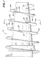
- FIG. 1-5 a screw conveyor in accordance with the present invention which is generally referred to by the numeral 10.
- the screw conveyor 10 as illustrated in Figures 1-5 is of the type that would generally be utilized within a decanter-type centrifuge.
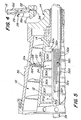
- the bowl structure and 'other typical structures of a decanter centrifuge have not been included except, in part, in Figure 5.
- the screw conveyor 10 generally comprises a longitudinally-extending hub 12 which is mounted for rotation about its central longitudinal axis.
- the conveyor 10 is contemplated to be rotated in a clockwise direction when viewed from the right-hand end of the conveyor hub 12.
- the direction of rotation has been identified in the figures by arrow 14.
- Extending from the conveyor hub 12 is a series of conveyor flights which are generally designated by the numeral 16. Each conveyor flight within the series has been designated separately, e.g., 16a, 16b, 16c, etc.
- the series of conveyor flights 16 form a spiral along at least a portion of the central hub 12 and are offset from one another. This offset is particularly shown in Figure 3 and is identified by the numeral 18. It should be noted, however, that the offset flights 16 are found on only a portion of the length of the conveyor 10. The number of offsets 18 will depend on the desire of the centrifuge designer and the application to which the centrifuge will be applied.
- each offset 18 between adjacent conveyor flights 16 is a spacer 20.
- the spacer 20, as particularly illustrated in Figure 3, is welded to the front surface of flight 16d and the rear surface of flight 16e.
- the offset 18 of the adjacent conveyor flights 16d, 16e and the spacer 20 form a channel 22 which extends along the projected length of the conveyor flights 16 and is open in the direction of rotation 14 of the conveyor 10.
- the channel 22 radially extends from the conveyor hub 12.
- the length of channel 22 may be varied by the centrifuge designer, as desired.
- An opening 24 is provided within the conveyor hub 12 for directing a rinse liquid into the channel 22. If left unobstructed, the channel 22 will direct the rinse liquid from the opening 24 to a position adjacent to the distal end of the conveyor flights 16.
- the movement of the heavy phase/solids material is generally in the direction of the conveyor rotation 14.
- the bowl (36 in Figure 5) is rotating faster than the conveyor 10 and in the same direction as the conveyor.
- the acceleration forces the rinse liquid to move along the inside surface of spacer 20 and radially outwardly through the channel 22.
- the rinse liquid reaches the surface of the heavy phase solids material, a portion will penetrate under the solids surface.
- the penetration of the rinse liquid will have the effect of washing within the solids while rising through the solids to their inner surface. Rinse liquid that cannot penetrate under the solids spills over the top of the solids, essentially in the direction opposite of that of conveyor rotation 14.
- the rotation of the conveyor in conjunction with the step formed by channel 22 causes a mixing to take place at each point of the conveyor flight offset.
- the peripheral end of the channel preferably includes a blocking member (not shown) so as to preclude the rinse liquid from flowing directly onto the bowl wall and then toward the trailing face of the conveyor flight.
- a portion of the forward conveyor flight 16e is directed or stepped inwardly into the channel 22.
- an inwardly projecting tab 26, which is formed as part of flight 16e projects into the channel 22 forming a step within the channel 22 and an outlet opening 28.
- Tab portion 26 deflects across the channel 22 and contacts the front surface of conveyor flight 16d.
- the rinse liquid is directed from the conveyor hub 12 through opening 24 into channel 22.
- the rinse liquid is forced to the back of the channel 22 while it is accelerated by the tangential speed of the channel.
- the step in the channel 22 formed by tab 26 then directs the rinse liquid out of the channel through outlet 28.
- the deflection of the rinse liquid can also be seen in Figure 2.
- the radial position of the outlet 28 may be varied as desired by the centrifuge designer and may be set differently on separate conveyor flights.
- the conveyor hub 12 includes a series of chambers 30.
- Each of the chambers is designated by a separate numeral, such as 30a, 30b, 30c, 30d, etc.
- a feed tube 34 is provided for each of the chambers 30, a feed tube 34 is provided.
- each chamber 30a, 30b, 30c, etc. includes a corresponding feed tube 32a, 32b, 32c, 32d, etc.
- the rinse liquid feed tubes 32 are generally positioned on the outside of the feed tube 34 for the mixture introduced into the centrifuge for separation. These feed tubes 32, 34 remain stationary with respect to the rotation of conveyor 10 and the centrifuge bowl 36.
- the introduction of the rinse liquid into the centrifuge bowl 36 may be controlled by means of the feed tube 34. If the outlets 28 from channel 22 are positioned in various radial locations, the position of introduction of the rinse liquid may be varied onto the surface of the conveyor flights 16 and into the heavy phase. Furthermore, by controlling the rate of feed of the rinse liquid into the various chambers 30, the pressure of the rinse liquid through the various channel 22 may be varied. Furthermore, by directing rinse liquid through various rinse feed tubes 32, the amount of rinsing and the location thereof may also be controlled.
- the forward conveyor flight portion 16e' includes an extension 19' of the portion of the edge of the channel that is radially inward of the outlet opening 28'.
- This extension 19' has an arc that is greater that the arc of the portion radially outward of the outlet opening 28'.
- the extension 19' is contemplated to assist in trapping the liquid within channel 22' as it moves from the opening 24' in the conveyor hub 12' toward the outlet 28'.
- FIG 7 there is shown a further embodiment of the channel within the offset of the conveyor flight portions.
- the channel does not terminate in an outlet opening extending through the surface of the forward conveyor flight portion as illustrated in Figures 2 and 6; rather, a curved portion 21" is positioned on the radially outward or distal end of channel 22".
- This curved portion 21" within channel 22" directs the rinse liquid forward across the surface of the trailing conveyor flight portion 16d", as illustrated by the arrows in Figure 7, in the direction of rotation of the conveyor 10".
- the curved portion 21" may be at any radial position, just as the ramp 26 in the embodiment shown in Figure 4 may be positioned to direct rinse liquid into the separated solids at different locations.
- the curve of portion 21" is intended to drive the rinse liquid tangentially into the cake, instead of moving outwardly to the bowl wall.
- FIGs 8 and 9 there is illustrated a further alternate embodiment of a conveyor 10''', including a plough 23''' formed on its distal edge of the offset conveyor flight portions.
- a plough shaped conveyor flight The advantages of a plough shaped conveyor flight are discussed in Caldwell U.S. Pat. No. 4,449,967.
- the offset 18''' provides rinse into the heavy phase solids material in the area of the concave curve of the plough 23'''.
- the outlet opening 28''' is positioned at the radial location of the plough 23''' and deflects the rinse liquid flow from the channel 22''' into the plough surface 23A''' on the trailing conveyor flight portion 16d'''.
- a centrifuge having a perforated bowl may incorporate the advantages of the present invention.
- Rinse liquid introduced through the channels between the conveyor flights could be used to wash the solids as they are moved toward their discharge.
- the perforated bowl portion may form only one section of the beach, may be positioned adjacent thereto, or may encompass the entire bowl wall such that both the rinse liquid and the separated liquid are discharged through the perforated bowl.
- the channel may be partially closed in the direction of rotation of the conveyor. This would include the addition of a flange projecting across the front of the channel from the forward conveyor flight toward the rear conveyor flight.
- a flange would extend partially across offset 18 from the forward conveyor flight 16e toward the face of the rear conveyor flight 16d and somewhat parallel to the spacer 20. Such an addition to the offset of the conveyor flights would limit the ability of the rinse liquid to spill over the top surface of the solids and direct more into the solids. This may also have the effect of mixing the rinse liquid at each offset flight portion. It is also possible to completely close the offset for a portion of the projection of the conveyor. Other variations are also contemplated and should become apparent to those skilled in the art.
- channels 22, 22', 22" and 22''' extend from the conveyor hub in a substantially radial direction. It may be desirable to offset this channel from a radial line.
- the present invention is contemplated to provide a less costly construction for achieving the desired rinse than known centrifuges or separators. Also the centrifuge may be less prone to plugging of the rinse passageways. Moreover, the present invention causes movement of the solids while mixing the solids at the primary point of rinse introduction. This results in greater rinsing efficiency, the use of less rinse water and better solids purity.
Landscapes
- Centrifugal Separators (AREA)
Claims (20)
- Zentrifugen-Schneckenförderer (10) miteiner in Längsrichtung verlaufenden zentralen Nabe (12),einer Förderschnecke (16), die über mindestens einen Teil der zentralen Nabe (12) eine Spirale bildet, wobei mindestens ein Teil der Förderschnecke (16) gegenüber einem angrenzenden Schneckenteil versetzt ist,einer Abstandhalteeinrichtung (20), die im Versatz (18) der Förderschnecke angeordnet ist, wobei die Abstandhalteeinrichtung und der Versatz in der Förderschnecke einen Kanal (22) bilden, und miteiner Einrichtung (24), mit der eine Spülflüssigkeit aus der Förderernabe in den Kanal (22) einleitbar ist.
- Zentrifugen-Schneckenförderer nach Anspruch 1, bei dem der von der Abstandhalteeinrichtung (20) und dem Versatz in der Förderschnecke (16) gebildete Kanal (22) von der zentralen Nabe (12) aus radial auswärts verläuft.
- Zentrifugen-Schneckenförderer nach Anspruch 1 oder 2, bei dem der Kanal (22) sich von der zentralen Nabe (12) zum distalen Ende der Förderschnecke (16) hin erstreckt.
- Zentrifugen-Schneckenförderer nach einem der Ansprüche 1 bis 3, bei dem die Förderschnecke (16) eine vordere und eine hintere Oberfläche aufweist, der axial hintere Teil (16d) der Förderschnecke vom Versatz (18) aus spiralartig entlang der Nabe (12) verläuft und der Abstandhalter (20) auf die hintere Oberfläche des axial vorderen Teils (16e) und auf die vordere Oberfläche des axial hinteren Teils (16d) der Förderschnecke aufgesetzt ist.
- Zentrifugen-Schneckenförderer nach einem der Ansprüche 1 bis 4, weiterhin mit einer im Kanal (22) vorgesehenen Einrichtung (26, 28), mit der die Spülflüssigkeit an einem Ort radial einwärts des distalen Endes der Förderschnecke (16) aus dem Kanal hinaus leitbar ist.
- Zentrifugen-Schneckenförderer nach Anspruch 5, bei dem die Leiteinrichtung in einem der versetzten Teile der Förderschnecke (16) eine Öffnung (28) aufweist, die mit dem Kanal (22) in Strömungsverbindung steht.
- Zentrifugen-Schneckenförderer nach Anspruch 5 oder 6, bei dem einer der versetzten Teil der Förderschnecke (16) ein Segment (26) radial einwärts des distalen Endes aufweist, das in den Kanal (22) hinein ausgelenkt ist, um eine Spülflüssigkeit aus dem Kanal auf die Förderschnecke zu richten.
- Zentrifugen-Schneckenförderer nach Anspruch 7 wenn abhängig vom Anspruch 6, bei dem das abgesetzte Segment (26) eine Lasche aufweist, die einteilig mit einem der versetzten Teil der Förderschnecke (16) gebildet ist, der in den Kanal (22) hinein ausgelenkt ist, um im Kanal einen Absatz nahe der Öffnung (28) auszubilden.
- Zentrifugen-Schneckenförderer nach einem der Ansprüche 1 bis 8, bei dem die Förderschnecke (16) eine Reihe von Gängen (16a, 16b, ...) aufweist, die jeweils bezüglich eines angrenzenden Schneckengangs versetzt sind, wobei aneinandergrenzende Schneckengänge paarweise zwischen sich eine Abstandhalteeinrichtung (20) aufweisen und jeweils einen Kanal (22) bilden, in den mittels einer entsprechenden Einrichtung (24) in der Förderernabe (12) eine Spülflüssigkeit einbringbar ist.
- Zentrifugen-Schneckenförderer nach Anspruch 9, weiterhin mit einer Reihe von Kammern (30), die in der zentralen Nabe (12) ausgebildet sind und jeweils mit einer zugehörigen Einrichtung (24) zur Zufuhr von Spülflüssigkeit in Strömungsverbindung stehen, mit der durch die Zufuhreinrichtung eine Spülflüssigkeit in einen entsprechenden der Kanäle (22) führbar ist, die zwischen den versetzten Gängen (16a, 16b, ...) der Förderschnecke ausgebildet sind.
- Zentrifugen-Schneckenförderer nach Anspruch 10, weiterhin mit einer Reihe von Speiserohren (32) für Spülflüssigkeit, mit denen jeweils eine Spülflüssigkeit in eine zugehörige Kammer (30) leitbar ist.
- Zentrifugen-Schneckenförderer nach einem der Ansprüche 1 bis 11 mit einer Austrittsöffnung (28'), mit der die Spülflüssigkeit an einer Stelle radial einwärts des distalen Endes der Förderschnecke (16) aus dem Kanal heraus leitbar ist, wobei die vordere Kante (19') des Versatzes aneinandergrenzender Schneckengänge (16d', 16e') an einer Stelle nahe der Förderernabe (12') von einem Bogen größerer Länge als der des Bogens des radial auswärts der Austrittsöffnung (28') liegenden Teils gebildet wird.
- Zentrifugen-Schneckenförderer nach einem der Ansprüche 1 bis 12, bei dem das distale Ende des Kanals (22") einen gekrümmten Teil (21") aufweist, mit dem die Spülflüssigkeit im wesentlichen in Drehrichtung des Förderers (10") aus dem Kanal richtbar ist.
- Zentrifugen-Schneckenförderer nach Anspruch 13, bei dem der gekrümmte Teil (21") sich auf dem Abstandhalter (20") befindet.
- Zentrifugen-Schneckenförderer nach einem der Ansprüche 1 bis 14, bei das distale Ende mindestens eines Teils der Schneckengänge (16d''', 16e''') einen Pflug (23"') mit konkaver Krümmung aufweist und der Kanal (22"') die Spülflüssigkeit auf die konkave Pflugfläche richtet.
- Rotierende Trennvorrichtung zum Trennen einer schweren Phase bzw. von Feststoffen von einer Flüssigkeit in einem Gemisch, wobei die Trennvorrichtung einen Schneckenförderer (10) nach einem der Ansprüche 1 bis 15, mit dem die Feststoffe transportierbar sind, sowie eine den Förderer umgebende Trommel (36) aufweist, die mit einer von der des Förderers unterschiedlichen Drehzahl rotiert, wobei die Trennvorrichtung
eine Kanaleinrichtung (22) aufweist, mit der eine Spülflüssigkeit bei der Drehung der Trommel (36) in diese leitbar ist und die die Spülflüssigkeit in die abgetrennte schwere Phase bzw. die Feststoffe richtet, während sie die schwere Phase bzw. die Feststoffe und die Spülflüssigkeit am Einführpunkt derselben miteinander mischt. - Trennvorrichtung nach Anspruch 16, bei der die Trommel (36) perforationsfrei ist.
- Trennvorrichtung nach Anspruch 16 oder 17, bei der die Kanaleinrichtung vom Kanal (22) des Förderers (10) gebildet wird.
- Trennvorrichtung nach einem der Ansprüche 16 bis 18, bei der die Trommel (36) einen zylindrischen und einen kegelstumpfförmigen Teil aufweist,mindestens ein Teil der Förderschnecke (16) sich von der zentralen Nabe (12) zu einem distalen Ende an einer Innenfläche der Trommel (36) erstreckt undder Kanal in Drehrichtung der Förderschnecke (16) offen ist.
- Trennvorrichtung nach einem der Ansprüche 16 bis 19, bei der die Trommel (36) einen zylindrischen Teil, einen Austrag für leichte Phase und einen Austrag für schwere Phase aufweist, wobei der Austrag für schwere Phase sich an einem Ende der Trommel (36) befindet, eine Einrichtung (34) vorgesehen ist, mit der eine Speiseflüssigkeit aus dem Förderer (10) in die Trommel einführbar ist, und die Förderschnecke (16) eine vordere und eine hintere Oberfläche aufweist, wobei die vordere Oberfläche allgemein dem Austrag für schwere Phase zugewandt ist.
Applications Claiming Priority (2)
| Application Number | Priority Date | Filing Date | Title |
|---|---|---|---|
| US08/304,073 US5509882A (en) | 1994-09-12 | 1994-09-12 | Decanter centrifuge having an offset conveyor flight to aid rinsing |
| US304073 | 1994-09-12 |
Publications (2)
| Publication Number | Publication Date |
|---|---|
| EP0700727A1 EP0700727A1 (de) | 1996-03-13 |
| EP0700727B1 true EP0700727B1 (de) | 2001-05-30 |
Family
ID=23174945
Family Applications (1)
| Application Number | Title | Priority Date | Filing Date |
|---|---|---|---|
| EP95306269A Expired - Lifetime EP0700727B1 (de) | 1994-09-12 | 1995-09-07 | Dekantierzentrifuge mit einer Förderschneckenwendel die Spülung erleichtert |
Country Status (5)
| Country | Link |
|---|---|
| US (1) | US5509882A (de) |
| EP (1) | EP0700727B1 (de) |
| JP (1) | JP3957336B2 (de) |
| DE (1) | DE69521090T2 (de) |
| DK (1) | DK0700727T3 (de) |
Families Citing this family (12)
| Publication number | Priority date | Publication date | Assignee | Title |
|---|---|---|---|---|
| DK143295A (da) * | 1995-12-18 | 1997-06-19 | Tetra Laval Holdings & Finance | Dekantercentrifuge |
| US6572524B1 (en) * | 2000-07-14 | 2003-06-03 | Alfa Laval Inc. | Decanter centrifuge having a heavy phase solids baffle |
| US6561965B1 (en) | 2000-10-20 | 2003-05-13 | Alfa Laval Inc. | Mist pump for a decanter centrifuge feed chamber |
| EP1308262A1 (de) * | 2001-10-31 | 2003-05-07 | Krauss-Maffei Kunststofftechnik GmbH | Extrusionsschnecke |
| WO2004060566A1 (ja) * | 2002-12-26 | 2004-07-22 | Tomoe Engineering Co., Ltd. | 遠心分離機 |
| AU2002360053A1 (en) * | 2002-12-26 | 2004-07-29 | Mitsubishi Chemical Corporation | Centrifugal separator |
| GB2410709B (en) * | 2004-02-07 | 2007-04-18 | Broadbent & Sons Ltd Thomas | Improving washing of separated solids in solid bowl and screen bowl decanting centrifuges |
| CN102240612A (zh) * | 2011-06-08 | 2011-11-16 | 山西恩必讴重工有限公司 | 煤泥水固液分离机可拆卸式螺旋叶片 |
| CA3021262A1 (en) * | 2016-04-19 | 2017-10-26 | Recover Energy Services Inc. | Oilfield centrifuge decanter for drilling waste drying method and apparatus |
| KR101794322B1 (ko) * | 2017-04-11 | 2017-11-07 | 한국플랜트서비스 주식회사 | 배연탈황설비의 석고슬러리 탈수 장치 |
| US11331679B2 (en) * | 2018-05-25 | 2022-05-17 | Tetra Laval Holdings & Finance S.A. | Centrifugal separator |
| CN118725975B (zh) * | 2024-08-27 | 2024-11-05 | 山东西王食品有限公司 | 一种植物油精炼工艺用离心脱胶装置 |
Family Cites Families (63)
| Publication number | Priority date | Publication date | Assignee | Title |
|---|---|---|---|---|
| US2184598A (en) * | 1939-12-26 | G jahn | ||
| US832191A (en) * | 1905-07-07 | 1906-10-02 | Wilhelm Holzer | Centrifugal separator. |
| US1028934A (en) * | 1911-09-16 | 1912-06-11 | Benjamin Denver Coppage | Combined conveyer and scraper for centrifugal machines. |
| US1027134A (en) * | 1911-10-23 | 1912-05-21 | Francis J Arend | Mechanical movement for producing a differential speed between driving and driven members. |
| US1927822A (en) * | 1926-02-16 | 1933-09-26 | Merco Centrifugal Separator Co | Centrifuge apparatus |
| US1614357A (en) * | 1926-02-19 | 1927-01-11 | Gamper Robert | Centrifugal separator |
| US1756194A (en) * | 1926-09-04 | 1930-04-29 | Haug Anton Joseph | Process and machine for thickening pulp |
| US1721230A (en) * | 1927-10-29 | 1929-07-16 | Molbach Elias Bernhard | Centrifugal separator |
| US2044996A (en) * | 1930-08-18 | 1936-06-23 | Lois W G Podbielniak | Method of securing counter current contact of fluids by centrifugal action |
| US2283457A (en) * | 1938-02-19 | 1942-05-19 | Joseph S Pecker | Centrifugal separator |
| NL63185C (de) * | 1940-11-22 | |||
| US2313540A (en) * | 1941-05-26 | 1943-03-09 | Laval Separator Co De | Machine for purifying liquids |
| NL81687C (de) * | 1941-08-14 | 1900-01-01 | ||
| US2435623A (en) * | 1942-03-11 | 1948-02-10 | Separator Nobel Ab | Centrifuges for separating from a liquid matters suspended or emulgated therein |
| US2593278A (en) * | 1945-04-12 | 1952-04-15 | Separation I Emulsion Et Le Me | Centrifuge for separating a liquid from solid material |
| US2578456A (en) * | 1946-07-31 | 1951-12-11 | Centrifuge Mechanical Equipmen | Centrifugal separator |
| US2614748A (en) * | 1947-07-29 | 1952-10-21 | Howard P Ritsch | Centrifuge for separating solids |
| US2612314A (en) * | 1949-03-28 | 1952-09-30 | Lewis L Huelsdonk | Centrifuge |
| US2670131A (en) * | 1951-05-23 | 1954-02-23 | Knowles Associates | Centrifuge with interstage washing |
| US2694520A (en) * | 1951-12-03 | 1954-11-16 | Goument Vear Oliver | Apparatus for separating butterfat from milk |
| GB733515A (en) * | 1952-05-28 | 1955-07-13 | Separator Ab | Improvements in or relating to the separating of liquids and solids |
| US2743864A (en) * | 1954-03-05 | 1956-05-01 | Bird Machine Co | Centrifuge with inclined conveyor blade and vanes for rapid collection of fine particles from suspensions |
| US2878993A (en) * | 1955-07-05 | 1959-03-24 | Wladzia G Podbielniak | Centrifugal countercurrent contacting method and apparatus |
| US3092582A (en) * | 1959-03-20 | 1963-06-04 | Black Clawson Co | Centrifuge |
| US3172851A (en) * | 1962-08-31 | 1965-03-09 | Centrifuging liquid-solids mixtures | |
| US3260369A (en) * | 1962-12-14 | 1966-07-12 | Lou A Gruenewaelder | Means for centrifugally clarifying water containing sewage sludges and the like |
| US3200068A (en) * | 1962-12-27 | 1965-08-10 | Combustion Eng | Recovering fines in a mechanical dehydrator |
| US3279687A (en) * | 1963-05-24 | 1966-10-18 | Bird Machine Co | Centrifuge |
| US3326457A (en) * | 1964-02-14 | 1967-06-20 | United States Steel Corp | Method and apparatus for steamassisted centrifugal dewatering |
| US3302873A (en) * | 1964-02-21 | 1967-02-07 | Pennsalt Chemicals Corp | Centrifugal solids deliquefying and treating process and apparatus |
| US3187998A (en) * | 1964-03-31 | 1965-06-08 | Vernon D Jarvis | Centrifugal extractor |
| US3285507A (en) * | 1964-12-02 | 1966-11-15 | Pennsalt Chemicals Corp | Screw-type solids discharge centrifuge having means to discharge light solids |
| US3228594A (en) * | 1965-02-05 | 1966-01-11 | Clifford L Amero | Centrifugal separator |
| US3348767A (en) * | 1965-04-19 | 1967-10-24 | Bird Machine Co | Centrifugal separator |
| US3368747A (en) * | 1965-10-20 | 1968-02-13 | Pennsalt Chemicals Corp | Centrifuge |
| NO120465B (de) * | 1965-10-21 | 1970-10-19 | Alfa Laval Ab | |
| DE1295494B (de) * | 1965-11-25 | 1969-05-14 | Westfalia Separator Ag | Schneckenzentrifuge mit Wascheinrichtung fuer die abgeschleuderten Feststoffe |
| US3398888A (en) * | 1966-08-18 | 1968-08-27 | Ethyl Corp | Centrifuge with improved discharge assembly |
| US3405866A (en) * | 1966-11-09 | 1968-10-15 | Bird Machine Co | Centrifuge |
| US3430850A (en) * | 1967-11-13 | 1969-03-04 | Perfection Eng Co Inc | Centrifugal separator |
| US3471081A (en) * | 1967-12-21 | 1969-10-07 | Ametek Inc | Acid feed pipe |
| US3707235A (en) * | 1971-03-19 | 1972-12-26 | Sweco Inc | Wastewater concentrator with plural distributors |
| IT995259B (it) * | 1972-09-11 | 1975-11-10 | Escher Wyss Ag | Centrifuga di chiarificazione |
| DE2304603A1 (de) * | 1973-01-31 | 1974-08-01 | Bayer Ag | Verfahren und vorrichtung zum zentrifugieren und waschen von feststofffluessigkeitssuspensionen |
| DE2349298C3 (de) * | 1973-10-01 | 1979-03-22 | Titan Separator A/S, Soeborg (Daenemark) | Schneckenzentrifuge mit einer vollwandigen Außentrommel |
| SU539611A1 (ru) * | 1974-06-25 | 1976-12-25 | Проектный И Научно-Исследовательский Институт "Гипроникель" | Пакет сепарирующих тарелок к центрифуге |
| SU535966A1 (ru) * | 1975-04-28 | 1976-11-25 | Всесоюзный научно-исследовательский и проектный институт галургии | Шнекова центрифуга |
| US4052304A (en) * | 1976-07-21 | 1977-10-04 | Cf&I Engineers, Inc. | Preheating device for centrifugal |
| SU644542A1 (ru) * | 1977-04-11 | 1979-01-30 | Московский технологический институт мясной и молочной промышленности | Центрифуга |
| US4298160A (en) * | 1977-05-24 | 1981-11-03 | Thomas Broadbent & Sons Limited | Solid bowl decanter centrifuges |
| US4190194A (en) * | 1978-07-28 | 1980-02-26 | Bird Machine Company, Inc. | Solids liquid separating centrifuge with solids classification |
| DE2901607C2 (de) * | 1979-01-17 | 1981-03-12 | Westfalia Separator Ag, 4740 Oelde | Vollmantelschneckenzentrifuge |
| US4299352A (en) * | 1979-03-23 | 1981-11-10 | Kobe, Inc. | Centrifuge apparatus |
| DE3216393A1 (de) * | 1982-05-03 | 1983-11-03 | Bayer Ag, 5090 Leverkusen | Schneckenzentrifuge mit waschvorrichtung |
| GB2121325A (en) * | 1982-06-07 | 1983-12-21 | Fsp | Cleaning centrifuge |
| US4449967A (en) * | 1982-06-17 | 1984-05-22 | Pennwalt Corporation | Conveyor flight configuration |
| DE3318793A1 (de) * | 1983-05-24 | 1985-01-24 | KHD Humboldt Wedag AG, 5000 Köln | Vorrichtung zum entfeuchten von schlamm |
| GB2160786B (en) * | 1984-06-26 | 1988-03-23 | Broadbent & Sons Ltd Thomas | Separating systems |
| US4731182A (en) * | 1985-11-18 | 1988-03-15 | Decanter Pty. Limited | Decanter centrifuge |
| US4654022A (en) * | 1986-01-31 | 1987-03-31 | Pennwalt Corporation | Rinsing on a solid bowl centrifuge |
| DE3624536A1 (de) * | 1986-07-19 | 1988-01-21 | Kloeckner Humboldt Deutz Ag | Schneckenzentrifuge |
| US5176616A (en) * | 1989-06-29 | 1993-01-05 | Kloeckner-Humboldt-Deutz Aktiengesellschaft | Method and apparatus for the after-treatment of the thick material in the thick material discharge region of a solid bowl worm centrifuge |
| WO1992005877A1 (en) * | 1990-09-27 | 1992-04-16 | Conoco Specialty Products Inc. | Countercurrent washing of solids in a decanter centrifuge |
-
1994
- 1994-09-12 US US08/304,073 patent/US5509882A/en not_active Expired - Lifetime
-
1995
- 1995-09-07 EP EP95306269A patent/EP0700727B1/de not_active Expired - Lifetime
- 1995-09-07 DK DK95306269T patent/DK0700727T3/da active
- 1995-09-07 DE DE69521090T patent/DE69521090T2/de not_active Expired - Fee Related
- 1995-09-11 JP JP23286395A patent/JP3957336B2/ja not_active Expired - Fee Related
Also Published As
| Publication number | Publication date |
|---|---|
| DE69521090D1 (de) | 2001-07-05 |
| DK0700727T3 (da) | 2001-07-30 |
| DE69521090T2 (de) | 2001-09-13 |
| JPH08103688A (ja) | 1996-04-23 |
| EP0700727A1 (de) | 1996-03-13 |
| JP3957336B2 (ja) | 2007-08-15 |
| US5509882A (en) | 1996-04-23 |
Similar Documents
| Publication | Publication Date | Title |
|---|---|---|
| EP0700727B1 (de) | Dekantierzentrifuge mit einer Förderschneckenwendel die Spülung erleichtert | |
| US4378906A (en) | Solid jacket centrifuge for material exchange between liquids | |
| US5520605A (en) | Method for accelerating a liquid in a centrifuge | |
| EP0602766B1 (de) | Dekantierzentrifuge zur hochgradigen Eindickung | |
| US5527474A (en) | Method for accelerating a liquid in a centrifuge | |
| EP0565268B1 (de) | Schneckenzentrifuge mit unterbrochenen Schneckenwendeln im konischen Austragsmantelteil | |
| US5948256A (en) | Centrifuge with cake churning | |
| US4245777A (en) | Centrifuge apparatus | |
| CA2437502C (en) | Solid-bowl screw centrifuge | |
| US5401423A (en) | Feed accelerator system including accelerator disc | |
| US6572524B1 (en) | Decanter centrifuge having a heavy phase solids baffle | |
| US5958235A (en) | Continuous-feed filtering- or screening-type centrifuge with reslurrying and dewatering | |
| US5735789A (en) | Centrifugal separator | |
| US4654022A (en) | Rinsing on a solid bowl centrifuge | |
| CA2431581A1 (en) | Pump vanes for a decanter centrifuge feed chamber | |
| AU2023235501B2 (en) | Decanter centrifuge with lamellae for improved fines recovery | |
| HK40062434B (en) | Heavy phase liquid discharge element for a centrifugal separator, centrifugal separator and method for separating two liquid phases | |
| HK40062434A (en) | Heavy phase liquid discharge element for a centrifugal separator, centrifugal separator and method for separating two liquid phases |
Legal Events
| Date | Code | Title | Description |
|---|---|---|---|
| PUAI | Public reference made under article 153(3) epc to a published international application that has entered the european phase |
Free format text: ORIGINAL CODE: 0009012 |
|
| AK | Designated contracting states |
Kind code of ref document: A1 Designated state(s): DE DK FR GB IT SE |
|
| 17P | Request for examination filed |
Effective date: 19960819 |
|
| RAP1 | Party data changed (applicant data changed or rights of an application transferred) |
Owner name: ALFA LAVAL SEPARATION INC. |
|
| 17Q | First examination report despatched |
Effective date: 19990421 |
|
| GRAG | Despatch of communication of intention to grant |
Free format text: ORIGINAL CODE: EPIDOS AGRA |
|
| GRAG | Despatch of communication of intention to grant |
Free format text: ORIGINAL CODE: EPIDOS AGRA |
|
| GRAH | Despatch of communication of intention to grant a patent |
Free format text: ORIGINAL CODE: EPIDOS IGRA |
|
| RAP1 | Party data changed (applicant data changed or rights of an application transferred) |
Owner name: ALFA LAVAL INC. |
|
| GRAH | Despatch of communication of intention to grant a patent |
Free format text: ORIGINAL CODE: EPIDOS IGRA |
|
| GRAA | (expected) grant |
Free format text: ORIGINAL CODE: 0009210 |
|
| AK | Designated contracting states |
Kind code of ref document: B1 Designated state(s): DE DK FR GB IT SE |
|
| REF | Corresponds to: |
Ref document number: 69521090 Country of ref document: DE Date of ref document: 20010705 |
|
| ITF | It: translation for a ep patent filed | ||
| REG | Reference to a national code |
Ref country code: DK Ref legal event code: T3 |
|
| ET | Fr: translation filed | ||
| REG | Reference to a national code |
Ref country code: GB Ref legal event code: IF02 |
|
| PLBE | No opposition filed within time limit |
Free format text: ORIGINAL CODE: 0009261 |
|
| STAA | Information on the status of an ep patent application or granted ep patent |
Free format text: STATUS: NO OPPOSITION FILED WITHIN TIME LIMIT |
|
| 26N | No opposition filed | ||
| PGFP | Annual fee paid to national office [announced via postgrant information from national office to epo] |
Ref country code: DK Payment date: 20080912 Year of fee payment: 14 |
|
| PGFP | Annual fee paid to national office [announced via postgrant information from national office to epo] |
Ref country code: IT Payment date: 20080926 Year of fee payment: 14 Ref country code: FR Payment date: 20080915 Year of fee payment: 14 |
|
| PGFP | Annual fee paid to national office [announced via postgrant information from national office to epo] |
Ref country code: GB Payment date: 20080910 Year of fee payment: 14 |
|
| PGFP | Annual fee paid to national office [announced via postgrant information from national office to epo] |
Ref country code: DE Payment date: 20080919 Year of fee payment: 14 |
|
| PGFP | Annual fee paid to national office [announced via postgrant information from national office to epo] |
Ref country code: SE Payment date: 20080908 Year of fee payment: 14 |
|
| EUG | Se: european patent has lapsed | ||
| REG | Reference to a national code |
Ref country code: DK Ref legal event code: EBP |
|
| GBPC | Gb: european patent ceased through non-payment of renewal fee |
Effective date: 20090907 |
|
| REG | Reference to a national code |
Ref country code: FR Ref legal event code: ST Effective date: 20100531 |
|
| PG25 | Lapsed in a contracting state [announced via postgrant information from national office to epo] |
Ref country code: FR Free format text: LAPSE BECAUSE OF NON-PAYMENT OF DUE FEES Effective date: 20090930 Ref country code: DE Free format text: LAPSE BECAUSE OF NON-PAYMENT OF DUE FEES Effective date: 20100401 |
|
| PG25 | Lapsed in a contracting state [announced via postgrant information from national office to epo] |
Ref country code: GB Free format text: LAPSE BECAUSE OF NON-PAYMENT OF DUE FEES Effective date: 20090907 |
|
| PG25 | Lapsed in a contracting state [announced via postgrant information from national office to epo] |
Ref country code: DK Free format text: LAPSE BECAUSE OF NON-PAYMENT OF DUE FEES Effective date: 20090930 |
|
| PG25 | Lapsed in a contracting state [announced via postgrant information from national office to epo] |
Ref country code: IT Free format text: LAPSE BECAUSE OF NON-PAYMENT OF DUE FEES Effective date: 20090907 |
|
| PG25 | Lapsed in a contracting state [announced via postgrant information from national office to epo] |
Ref country code: SE Free format text: LAPSE BECAUSE OF NON-PAYMENT OF DUE FEES Effective date: 20090908 |