EP0700566B1 - Schutzsystem einer optischen scheibe - Google Patents
Schutzsystem einer optischen scheibe Download PDFInfo
- Publication number
- EP0700566B1 EP0700566B1 EP94931466A EP94931466A EP0700566B1 EP 0700566 B1 EP0700566 B1 EP 0700566B1 EP 94931466 A EP94931466 A EP 94931466A EP 94931466 A EP94931466 A EP 94931466A EP 0700566 B1 EP0700566 B1 EP 0700566B1
- Authority
- EP
- European Patent Office
- Prior art keywords
- protective film
- washer
- optical disk
- diameter
- protection system
- Prior art date
- Legal status (The legal status is an assumption and is not a legal conclusion. Google has not performed a legal analysis and makes no representation as to the accuracy of the status listed.)
- Expired - Lifetime
Links
- 230000004224 protection Effects 0.000 title claims abstract description 53
- 230000003287 optical effect Effects 0.000 title claims abstract description 34
- 230000001681 protective effect Effects 0.000 claims abstract description 47
- 239000000853 adhesive Substances 0.000 claims abstract description 15
- 230000001070 adhesive effect Effects 0.000 claims abstract description 15
- 238000000034 method Methods 0.000 claims description 10
- 238000005520 cutting process Methods 0.000 claims description 7
- 239000011248 coating agent Substances 0.000 claims description 4
- 238000000576 coating method Methods 0.000 claims description 4
- 238000002360 preparation method Methods 0.000 claims description 3
- 239000000463 material Substances 0.000 claims 2
- 239000010408 film Substances 0.000 description 5
- 239000011159 matrix material Substances 0.000 description 5
- 239000004417 polycarbonate Substances 0.000 description 5
- 229920000515 polycarbonate Polymers 0.000 description 5
- 210000000078 claw Anatomy 0.000 description 3
- 238000004519 manufacturing process Methods 0.000 description 3
- 239000003292 glue Substances 0.000 description 2
- 230000002093 peripheral effect Effects 0.000 description 2
- 238000007789 sealing Methods 0.000 description 2
- 229920000297 Rayon Polymers 0.000 description 1
- 239000002390 adhesive tape Substances 0.000 description 1
- 230000015556 catabolic process Effects 0.000 description 1
- 238000001816 cooling Methods 0.000 description 1
- 239000013039 cover film Substances 0.000 description 1
- 230000007423 decrease Effects 0.000 description 1
- 238000006731 degradation reaction Methods 0.000 description 1
- 230000010339 dilation Effects 0.000 description 1
- 230000003292 diminished effect Effects 0.000 description 1
- 239000000428 dust Substances 0.000 description 1
- 238000010438 heat treatment Methods 0.000 description 1
- 238000003780 insertion Methods 0.000 description 1
- 230000037431 insertion Effects 0.000 description 1
- 239000010410 layer Substances 0.000 description 1
- 238000004806 packaging method and process Methods 0.000 description 1
- 230000002028 premature Effects 0.000 description 1
- 239000011241 protective layer Substances 0.000 description 1
- 239000002964 rayon Substances 0.000 description 1
- 238000010008 shearing Methods 0.000 description 1
- 230000035939 shock Effects 0.000 description 1
- 238000003892 spreading Methods 0.000 description 1
- 125000000391 vinyl group Chemical group [H]C([*])=C([H])[H] 0.000 description 1
- 229920002554 vinyl polymer Polymers 0.000 description 1
- 239000002699 waste material Substances 0.000 description 1
Images


Classifications
-
- G—PHYSICS
- G11—INFORMATION STORAGE
- G11B—INFORMATION STORAGE BASED ON RELATIVE MOVEMENT BETWEEN RECORD CARRIER AND TRANSDUCER
- G11B7/00—Recording or reproducing by optical means, e.g. recording using a thermal beam of optical radiation by modifying optical properties or the physical structure, reproducing using an optical beam at lower power by sensing optical properties; Record carriers therefor
- G11B7/24—Record carriers characterised by shape, structure or physical properties, or by the selection of the material
- G11B7/24097—Structures for detection, control, recording operation or replay operation; Special shapes or structures for centering or eccentricity prevention; Arrangements for testing, inspecting or evaluating; Containers, cartridges or cassettes
Definitions
- the present invention relates to a protection system to be applied on one side of reading a center-piercing optical disc of predetermined diameter, this system comprising a annular protective sheet, substantially transparent, having a first face intended to be applied to the read side of the optical disc and a second face opposite to the first, and a diameter outer edge and an inner edge diameter such as these edges each come into contact on the face of disc read in an area with no information optical, the internal edge diameter being greater than diameter of the central bore.
- This same bonding system can cause, following heating, uneven dilation of the protection against the disc, causing in a first a temporary deformation of the protection following the greater thermal inertia of the disc; secondly, the protection cooling faster than the disc, the shearing phenomenon causes the glue ring to slide; in one third time, the disc, also cooled, resumes its initial shape thus causing deformation protection.
- the present invention aims to carry remedy the disadvantages presented by the known state of the technique.
- the protection system will be easy to manufacture and replace if it is itself damaged. Its application on the disc will be particularly easy, without the need for an application centralizer.
- a protection system of the type described at the beginning further comprising a fixing washer centrally connected to the annular protective sheet and having an internal edge of diameter equal to diameter of the central hole of the optical disc, this washer having one face at least partially adhesive intended to adhere to the reading face of the optical disc in at least part of an area central of it, devoid of optical information and not covered by the protective sheet.
- the present invention also relates to an optical disc equipped with a protection system according to the invention.
- the invention also covers a method of preparation of such a protection system, as well as is indicated in particular in claims 12 to 14.
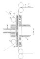
- Figure 1 shows schematically and in section an optical disc provided with a system of protection according to the invention, in the reading position.
- Figure 2 shows a perspective view deployed of a protection system according to the invention.
- Figure 3 shows an axial sectional view of a protection system according to the invention.
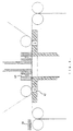
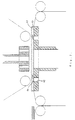
- Figures 4 to 7 show the different stages of a protection system preparation process according to the invention.
- a disc 1 with optical reading is arranged on a drive shaft in rotation 2 of the reading device not shown.
- a lens 3 of the read head of this device is shown schematically as well that the LASER optical beam which reads the information numerical worn on the reverse of the upper side 4 of the disk. No such information is found or in the peripheral zone 5 of the disk, nor in its zone central 6; the area with digital information is shown in Figure 1 by a thicker line 7.
- an annular protective sheet 9 On the so-called reading side of the disc, designated by the reference 8, is applied, by a first front, an annular protective sheet 9 in a film transparent.
- This sheet has an outer edge 10 and an internal edge 11 such that these edges come into contact on the read side 8 of the disc, in a area lacking digital information from it, that is to say opposite zones 5 and 6 respectively.
- diameter of the inner edge 11 of the protective sheet 9 is greater than that of the central bore 14 of the disc.
- the protection system according to the invention further includes a fixing washer 12, connected centrally to the annular protective sheet 9.
- This washer 12 has an internal edge 13 of diameter equal to the diameter of the central hole 14 of the disc optical. It has a face 15 at least partially adhesive which adheres to the reading face 8 in at least part of a central area of the disc, which lacks optical information and is not covered by the protective sheet 9.
- connection between the transparent protective sheet 9 and the fixing washer 12 is obtained by the fact that the latter has an outer edge 16 of greater diameter the diameter of the inner edge 11 of the sheet protection 9.
- the washer thus adheres by its face adhesive on the inner periphery of the second side 17, opposite the first aforementioned, of the sheet of protection.
- the fixing washer 12 advantageously has an outer edge 16 such that it is not in in front of an optical information zone of the disc.
- the fixing washer 12 is formed from a strip adhesive, which allows good adhesion to the disc, while authorizing his detachment from it by peeling, which facilitates both fixing and replacing of the protection system on the disc.
- the protective sheet 9 and the reading face 8 of the disc are held together not only by through the adhesion of the fixing washer 12 in the center of disc 1, but also by force electrostatic created between the transparent sheet of protection and disk. This is to avoid thermal expansion problems known to systems of protection of the prior art.
- the following fixing washer has a predetermined thickness.
- she When she is inserted, as in Figure 1, between the head of the rotation drive shaft 2 of the device reading and reading side 8, it lifts the disc and therefore moves lens 3 away from a distance which compensates for the focusing error generated by the presence of the transparent protective sheet 9 located between lens 3 and the reading face of the disc.
- This arrangement offers the great advantage of bring lens 3 back from the focusing system reading device at nominal position established by manufacturers of optical disc drives.
- the focus system correction capabilities does are therefore not diminished by the presence of the leaf protection, as is the case with the technique anterior.
- the protective sheet 9, provided with the washer 12 is housed before its application on the disc, in an envelope 18, for example of paper plasticized.
- This envelope includes a pan 19, adjacent on the aforesaid second face 17 of the protective sheet 9 and at least two flaps, in this case four flaps 20 to 23, which are each connected to an edge from side 19 and can be folded over on the first side 24 of protective sheet 9, face which is intended coming into contact with the reading face 8 of the disc.
- these flaps are cut and sized so as to form together a opening 25 of diameter equal to or less than the edge inner 11 ( Figure 1) of the protective sheet, this which releases the adhesive part of the fixing washer 12. Note that these flaps are simply folded and don't care about each other; they are not no no longer connected to the protective sheet.
- the pan 19 may have a gripping tab on the outside 26.
- the pan 19 also has a central opening 27. This can correspond to the opening 25 in the flaps. She can also have a different dimension, provided that its diameter is not less than that of the edge internal 13 of the fixing washer 12.
- the protection system according to the invention further includes a cover film 28 which covers the flaps and their opening so that they can be peeled from them before use.
- a cover film 28 which covers the flaps and their opening so that they can be peeled from them before use.
- Flaps 20 and 23 deploy then by sliding between the reading face 8 of the disc and the first face 24 of the protective sheet. This remains fixed in position by the washer fixing 12 which adheres to the disc and which therefore retains it.
- Figures 4 to 7 illustrate a mode of possible manufacturing of a following protection system the invention as illustrated in Figure 1.
- an adhesive strip 30 is carried out step by step in the direction indicated by the arrow 31 so as to pass horizontally between two return rollers 32 and 33.
- a strip 34 for example in transparent polycarbonate, is not unrolled step by step in the direction of arrow 35 so as to pass horizontally some distance below the adhesive tape 30.
- the bands is at least one punch 36 movable up and down.
- the bands we can also observe at least one punch 37, movable up and down.
- the punches are spaced from each other, and a matrix 38 has been introduced, from the left on the drawing, between the two strips 30 and 34 to be cut.
- This matrix is conformed at the top so as to allow cutting in the strip 30 of washers having the shape of fixing washers 12 and at the bottom so as to allow cutting in the strip 34 of annular sheets having the shape of the sheets of protection 9.
- the cutting step is illustrated in the figure 5, where the two punches 36 and 37 are brought together, one of the other and press between them the strip 30, the matrix 38 and strip 34. Cutting waste corresponding to central openings of the fixing washers and protective ring sheets are evacuated by down suction in a central bore 40 of the punch 37. The call for air takes place through the bore center 39 of punch 36, through an opening central of the matrix 38.
- the punches 36 and 37 are again discarded and the matrix 38 returns in its initial position, on the left in Figure 6.
- the punches 36 and 37 are then again brought together so as to press them together a cut-out fixing washer and an annular sheet protective cover.
- the punches are again moved aside to allow insertion above the system protection according to the invention of a carriage 43 from from the right in the drawing.
- the protection system is meanwhile maintained by a downward suction through the bores 42 of the punch 37.
- the suction through the bores 42 is stopped, while that a new aspiration is created by the orifices 44 of the carriage and the central cavity 45 thereof.
- the protection system is then taken away by the trolley 43 to the right, after further spacing of the hallmark 37.
- the protection system is then transferred to a wrapping device known per se, by example an H8H device from Multipli, then to a sealing film application device also known per se.
- the thickness of the fixing washer 12 of the protection system according to the invention is then calculated based on this focusing error.
Landscapes
- Optical Record Carriers And Manufacture Thereof (AREA)
- Optical Recording Or Reproduction (AREA)
- Manufacturing Optical Record Carriers (AREA)
- Gyroscopes (AREA)
Claims (14)
- Schutzsystem zum Aufbringen auf einer Leseseite bzw. -fläche (8) einer optisch zu lesenden Scheibe bzw. Platte (1) mit zentraler Bohrung (14) mit vorbestimmtem Durchmesser, umfassend eine ringförmige, im wesentlichen transparente Schutzfolie (9), die eine erste Seite (24), die dafür bestimmt ist, auf der Leseseite (8) der optischen Scheibe aufgebracht zu werden, und eine zweite, der ersten gegenüberliegende Seite (17) und einen Durchmesser des äußeren Randes (10) und einen Durchmesser des inneren Randes (11) aufweist, sodaß diese Ränder jeweils mit der Leseseite (8) der Scheibe in einer von optischen Informationen derselben freien zone in Kontakt gelangen, wobei der Durchmesser des inneren Randes (11) größer als der Durchmesser der zentralen Bohrung (14) ist,
dadurch gekennzeichnet, daß es außerdem eine Festlegungslochscheibe (12) umfaßt, die zentral mit der Schutzfolie bzw. dem Schutzblatt (9) verbunden ist und einen Innenrand (13) mit einem dem Durchmesser der zentralen Bohrung (14) der optischen Scheibe gleichen Durchmesser aufweist, welche Lochscheibe (12) eine wenigstens teilweise haftfähige Seite bzw. Fläche (15) aufweist, die dazu bestimmt ist, an der Leseseite (8) der optischen Scheibe in wenigstens einem Teil eines zentralen Bereiches derselben, welcher frei von optischen Informationen ist und nicht durch die Schutzfolie bedeckt ist, anzuhaften. - System nach Anspruch 1, dadurch gekennzeichnet, daß die Lochscheibe (12) einen Außenrand (16) mit gegenüber dem Durchmesser des Innenrandes (11) der Schutzfolie (9) größerem Durchmesser aufweist.
- System nach Anspruch 2, dadurch gekennzeichnet, daß die Seite (15) der Lochscheibe (12), die dazu bestimmt ist, auf der Leseseite (8) der optischen Scheibe anzuhaften, vollständig haft fähig ist und daß sie auch auf dem Innenumfang der zweiten Seite (17) der Schutzfolie (9) anhaftet.
- System nach einem der Ansprüche 1 bis 3, dadurch gekennzeichnet, daß die Festlegungslochscheibe (12) ausgehend von einem Klebeband gebildet ist, das in der Klebeposition auf der Scheibe ausgehend von derselben abziehbar ist.
- System nach einem der Ansprüche 1 bis 4, dadurch gekennzeichnet, daß die Schutzfolie (9) und die Leseseite (8) der optischen Scheibe untereinander in der Aufbringungsposition von einer auf der anderen eine elektrostatische Kraft aufweisen, welche sie zusammenhält.
- System nach einem der Ansprüche 1 bis 5, dadurch gekennzeichnet, daß die Lochscheibe (12) eine Dicke aufweist, welche bestimmt ist, wenn sie zwischen einem Drehantriebskopf (2) der optischen Scheibe einer Lesevorrichtung für diese Scheibe und der Leseseite (8) der letzteren eingesetzt ist, einen durch das Vorhandensein der Schutzfolie (9) zwischen der Lesevorrichtung (3) und der Leseseite (8) der Scheibe bewirkten Fokussierfehler zu kompensieren.
- Schutzsystem nach einem der Ansprüche 1 bis 6, dadurch gekennzeichnet, daß es außerdem eine Hülle (18) umfaßt, in welcher die mit ihrer Festlegungslochscheibe (12) versehene Schutzfolie (9) angeordnet ist, und daß diese Hülle (18) eine Fläche (19) benachbart der zweiten Seite (17) der Schutzfolie (9) umfaßt, welche zentral mit einer Öffnung (27) durchbohrt ist, welche einen Durchmesser mindestens gleich wie jenen des Innenrandes (13) der Lochscheibe (12) und wenigstens zwei an der obengenannten Fläche (19) festgelegte Umschläge bzw. Klappen (20 - 23) aufweist, sodaß diese über die erste Seite (24) der Schutzfolie (9) gefaltet werden können, wobei diese wenigstens zwei Umschläge (20 - 23) gemeinsam eine Öffnung (25) mit einem dem inneren Rand (11) der Schutzfolie (9) gleichen oder kleineren Durchmesser ausbilden, welcher den haftfähigen Bereich der Seite (15) der Festlegungslochscheibe (12), die dazu bestimmt ist, auf der Leseseite (8) der optischen Scheibe anzuhaften, freiläßt.
- Schutzsystem nach Anspruch 7, dadurch gekennzeichnet, daß die Hülle (18) vier Umschläge (20 - 23), die über die erste Seite (24) der Schutzfolie (9) gefaltet sind, aufweist.
- Schutzsystem nach einem der Ansprüche 7 oder 8, dadurch gekennzeichnet, daß die Fläche (19) mit einer Greiflasche (26) versehen ist, welche es erlaubt, einen Zug auf die Hülle (18) auszuüben und sie von der Schutzfolie (9) zu trennen, wenn die Festlegungslochscheibe (12) an einer optischen Scheibe anhaftet.
- Schutzsystem nach einem der Ansprüche 7 bis 9, dadurch gekennzeichnet, daß wenigstens zwei Umschläge (20 - 23) und ihre Öffnung (25) von einem abziehbaren Abdeckfilm (28) bedeckt sind und daß gegebenenfalls die Fläche (19) ebenfalls von einem derartigen Film (29) bedeckt ist.
- Optische Scheibe, ausgestattet mit einem Schutz system gemäß einem der Ansprüche 1 bis 6.
- Verfahren zur Herstellung eines Schutzsystems für eine optische Scheibe nach einem der Ansprüche 1 bis 6, umfassendein Ausschneiden der ringförmigen Schutzfolie (9), ausgehend von einem ersten Materialband (34), und der Festlegungslochscheibe (12), ausgehend von einem zweiten, haftfähigen Materialband (30), undeine Festlegung der Festlegungslochscheibe (12) im Zentrum der ringförmigen Schutzfolie (9).
- Verfahren zur Herstellung eines Schutzsystems für eine optische Scheibe nach einem der Ansprüche 7 bis 10, dadurch gekennzeichnet, daß es umfaßtein Ausschneiden der ringförmigen Schutzfolie (9), ausgehend von einem ersten Materialband (34), und der Festlegungslochscheibe (12), ausgehend von einem zweiten, haftfähigen Materialband (30),eine Festlegung der Festlegungslochscheibe (12) im Zentrum der ringförmigen Schutzfolie (9), undein Einführen der ringförmigen Schutzfolie (9), die mit der Festlegungslochscheibe (12) versehen ist, in das Innere einer Hülle (18).
- Verfahren zur Herstellung gemäß Anspruch 13, dadurch gekennzeichnet, daß es außerdem ein Anbringen eines abziehbaren Überzugsfilms (28, 29) auf den Umschlägen (20 - 23) der Hülle (18) und gegebenenfalls auf der Fläche (19) derselben umfaßt.
Applications Claiming Priority (3)
| Application Number | Priority Date | Filing Date | Title |
|---|---|---|---|
| BE9301220 | 1993-11-05 | ||
| BE9301220A BE1007702A5 (fr) | 1993-11-05 | 1993-11-05 | Protege face active de disques numeriques a lecture optique. |
| PCT/BE1994/000084 WO1995012881A1 (fr) | 1993-11-05 | 1994-11-07 | Systeme de protection de disque a lecture optique |
Publications (2)
| Publication Number | Publication Date |
|---|---|
| EP0700566A1 EP0700566A1 (de) | 1996-03-13 |
| EP0700566B1 true EP0700566B1 (de) | 1999-04-07 |
Family
ID=3887527
Family Applications (1)
| Application Number | Title | Priority Date | Filing Date |
|---|---|---|---|
| EP94931466A Expired - Lifetime EP0700566B1 (de) | 1993-11-05 | 1994-11-07 | Schutzsystem einer optischen scheibe |
Country Status (6)
| Country | Link |
|---|---|
| EP (1) | EP0700566B1 (de) |
| AT (1) | ATE178735T1 (de) |
| AU (1) | AU8054594A (de) |
| BE (1) | BE1007702A5 (de) |
| DE (1) | DE69417741D1 (de) |
| WO (1) | WO1995012881A1 (de) |
Families Citing this family (3)
| Publication number | Priority date | Publication date | Assignee | Title |
|---|---|---|---|---|
| US6192025B1 (en) * | 1999-05-05 | 2001-02-20 | Yong E. Chen | Structure for protecting reading area of compact disc and device for applying same |
| JP2002117584A (ja) * | 2000-10-06 | 2002-04-19 | Sony Corp | 光学記録媒体およびその製造方法 |
| EP1343157B1 (de) * | 2002-03-07 | 2007-05-23 | FUJIFILM Corporation | Optisches Aufzeichnungsmedium |
Family Cites Families (6)
| Publication number | Priority date | Publication date | Assignee | Title |
|---|---|---|---|---|
| US4319252A (en) * | 1980-07-21 | 1982-03-09 | Drexler Technology Corporation | Optical data storage and recording medium having a replaceable protective coverplate |
| US4556968A (en) * | 1983-03-31 | 1985-12-03 | Storage Technology Partners Ii | Unconstrained removable protective cover for optical disk |
| US4736966A (en) * | 1986-02-20 | 1988-04-12 | Drexler Technology Corporation | Data card with peelable protective layers |
| US4879710A (en) * | 1988-04-20 | 1989-11-07 | Mutsuo Iijima | Optical disc protector and method for applying same |
| JPH02165441A (ja) * | 1988-12-17 | 1990-06-26 | Sony Corp | 剥離可能な保護膜を有する光情報記録媒体 |
| JPH04344323A (ja) * | 1991-05-21 | 1992-11-30 | Canon Inc | 光記録読取方式 |
-
1993
- 1993-11-05 BE BE9301220A patent/BE1007702A5/fr not_active IP Right Cessation
-
1994
- 1994-11-07 AT AT94931466T patent/ATE178735T1/de not_active IP Right Cessation
- 1994-11-07 DE DE69417741T patent/DE69417741D1/de not_active Expired - Lifetime
- 1994-11-07 WO PCT/BE1994/000084 patent/WO1995012881A1/fr not_active Ceased
- 1994-11-07 AU AU80545/94A patent/AU8054594A/en not_active Abandoned
- 1994-11-07 EP EP94931466A patent/EP0700566B1/de not_active Expired - Lifetime
Also Published As
| Publication number | Publication date |
|---|---|
| WO1995012881A1 (fr) | 1995-05-11 |
| EP0700566A1 (de) | 1996-03-13 |
| AU8054594A (en) | 1995-05-23 |
| BE1007702A5 (fr) | 1995-10-03 |
| ATE178735T1 (de) | 1999-04-15 |
| DE69417741D1 (de) | 1999-05-12 |
Similar Documents
| Publication | Publication Date | Title |
|---|---|---|
| EP2304493B1 (de) | Verfahren zur übertragung eines teils eines funktionalen films | |
| CN1214387C (zh) | 光盘保护盒子 | |
| JP2955368B2 (ja) | 光データ貯蔵装置のための半永久的エンクロージャ | |
| US5819926A (en) | Package for a recording medium and method of assembling same | |
| EP0960831A1 (de) | Mit einem Coupon versehene Verpackung sowie Verfahren zur Herstellung dieser Verpackung | |
| FR2475271A1 (fr) | Structure de memoire permanente, a inscription thermo-optique et lecture optique, et procede d'inscription dans une telle structure | |
| EP0700566B1 (de) | Schutzsystem einer optischen scheibe | |
| US6081501A (en) | Attachment system for write-protect ring for optical disk | |
| EP0801778A1 (de) | Anhaftende hülle | |
| FR2459520A1 (fr) | Procede pour fabriquer des etiquettes imprimees adhesives destinees a etre collees sur des flacons, et etiquettes obtenues par ce procede | |
| FR2679888A1 (fr) | Procede et dispositif pour raccorder en continuite deux feuils minces. | |
| EP0629990A1 (de) | Selbstklebende Etiketten und Verfahren zur Herstellung derselben | |
| US6978469B2 (en) | Disc protector | |
| EP0277076A2 (de) | Verpackung gegen Diebstahl für einen magnetischen oder anderen Aufzeichnungsträger mit durchgehendem Loch, wie z.B. Kompakt-Disk-Platte, Kassette oder ähnliches | |
| EP0502785B1 (de) | Verfahren zum Abtasten der Form eines beliebigen, elastisch verformbaren Artikels, insbesondere zum Abtasten einer Brillengestellsöffnung | |
| FR3072050B1 (fr) | Etiquette textile adhesive et procede de fabrication d'une telle etiquette | |
| EP3912799B1 (de) | Vorrichtung zum anbringen und positionieren mehrerer markierungen | |
| EP1467335B1 (de) | Etikett, insbesondere für Behälter von kosmetischen Produkten | |
| JP3035111U (ja) | コンパクトディスクの表面保護装置 | |
| EP0916581A1 (de) | Verfahren und Vorrichtung zum automatischen Ablösen oder Entfernen von klebenden Kennzeichnungselementen | |
| FR2555790A1 (fr) | Procede de fabrication de curseurs pour tetes de lecture de disques magnetiques, et curseur realise par sa mise en oeuvre | |
| EP3330059A1 (de) | Klebespendevorrichtung und spleissvorrichtung für schläuche, die eine solche spendevorrichtzung umfasst | |
| JP3924240B2 (ja) | 光ディスクの製造装置 | |
| FR3106343A1 (fr) | Etiquette avec languette de préhension | |
| EP0624465A1 (de) | Vorrichtung zum zeitweiligen Verschweissen von Dokumenten auf einer Kunststoffbahn |
Legal Events
| Date | Code | Title | Description |
|---|---|---|---|
| PUAI | Public reference made under article 153(3) epc to a published international application that has entered the european phase |
Free format text: ORIGINAL CODE: 0009012 |
|
| 17P | Request for examination filed |
Effective date: 19951227 |
|
| AK | Designated contracting states |
Kind code of ref document: A1 Designated state(s): AT BE CH DE DK ES FR GB IE IT LI LU NL PT SE |
|
| REG | Reference to a national code |
Ref country code: CH Ref legal event code: PLI Owner name: CHIRCHI, MOUNIR TRANSFER- TECHMOUN S.A. |
|
| RAP3 | Party data changed (applicant data changed or rights of an application transferred) |
Owner name: CHIRCHI, MOUNIR |
|
| 111L | Licence recorded |
Free format text: 961010 0100 TECHMOUN S.A. |
|
| GRAG | Despatch of communication of intention to grant |
Free format text: ORIGINAL CODE: EPIDOS AGRA |
|
| 17Q | First examination report despatched |
Effective date: 19980702 |
|
| REG | Reference to a national code |
Ref country code: CH Ref legal event code: PLI Owner name: CHIRCHI, MOUNIR TRANSFER- TECHMOUN S.A. |
|
| GRAG | Despatch of communication of intention to grant |
Free format text: ORIGINAL CODE: EPIDOS AGRA |
|
| GRAH | Despatch of communication of intention to grant a patent |
Free format text: ORIGINAL CODE: EPIDOS IGRA |
|
| GRAH | Despatch of communication of intention to grant a patent |
Free format text: ORIGINAL CODE: EPIDOS IGRA |
|
| GRAA | (expected) grant |
Free format text: ORIGINAL CODE: 0009210 |
|
| RAP3 | Party data changed (applicant data changed or rights of an application transferred) |
Owner name: CHIRCHI, MOUNIR |
|
| RAP1 | Party data changed (applicant data changed or rights of an application transferred) |
Owner name: HUBERLAND, XAVIER Owner name: CHIRCHI, MOUNIR |
|
| AK | Designated contracting states |
Kind code of ref document: B1 Designated state(s): AT BE CH DE DK ES FR GB IE IT LI LU NL PT SE |
|
| PG25 | Lapsed in a contracting state [announced via postgrant information from national office to epo] |
Ref country code: SE Free format text: THE PATENT HAS BEEN ANNULLED BY A DECISION OF A NATIONAL AUTHORITY Effective date: 19990407 Ref country code: NL Free format text: LAPSE BECAUSE OF FAILURE TO SUBMIT A TRANSLATION OF THE DESCRIPTION OR TO PAY THE FEE WITHIN THE PRESCRIBED TIME-LIMIT Effective date: 19990407 Ref country code: IT Free format text: LAPSE BECAUSE OF FAILURE TO SUBMIT A TRANSLATION OF THE DESCRIPTION OR TO PAY THE FEE WITHIN THE PRE;WARNING: LAPSES OF ITALIAN PATENTS WITH EFFECTIVE DATE BEFORE 2007 MAY HAVE OCCURRED AT ANY TIME BEFORE 2007. THE CORRECT EFFECTIVE DATE MAY BE DIFFERENT FROM THE ONE RECORDED.SCRIBED TIME-LIMIT Effective date: 19990407 Ref country code: ES Free format text: THE PATENT HAS BEEN ANNULLED BY A DECISION OF A NATIONAL AUTHORITY Effective date: 19990407 Ref country code: AT Free format text: LAPSE BECAUSE OF FAILURE TO SUBMIT A TRANSLATION OF THE DESCRIPTION OR TO PAY THE FEE WITHIN THE PRESCRIBED TIME-LIMIT Effective date: 19990407 |
|
| REF | Corresponds to: |
Ref document number: 178735 Country of ref document: AT Date of ref document: 19990415 Kind code of ref document: T |
|
| REG | Reference to a national code |
Ref country code: CH Ref legal event code: EP |
|
| REG | Reference to a national code |
Ref country code: IE Ref legal event code: FG4D Free format text: FRENCH |
|
| REF | Corresponds to: |
Ref document number: 69417741 Country of ref document: DE Date of ref document: 19990512 |
|
| PG25 | Lapsed in a contracting state [announced via postgrant information from national office to epo] |
Ref country code: PT Free format text: LAPSE BECAUSE OF FAILURE TO SUBMIT A TRANSLATION OF THE DESCRIPTION OR TO PAY THE FEE WITHIN THE PRESCRIBED TIME-LIMIT Effective date: 19990707 Ref country code: DK Free format text: LAPSE BECAUSE OF FAILURE TO SUBMIT A TRANSLATION OF THE DESCRIPTION OR TO PAY THE FEE WITHIN THE PRESCRIBED TIME-LIMIT Effective date: 19990707 |
|
| PG25 | Lapsed in a contracting state [announced via postgrant information from national office to epo] |
Ref country code: DE Free format text: LAPSE BECAUSE OF FAILURE TO SUBMIT A TRANSLATION OF THE DESCRIPTION OR TO PAY THE FEE WITHIN THE PRESCRIBED TIME-LIMIT Effective date: 19990708 |
|
| NLV1 | Nl: lapsed or annulled due to failure to fulfill the requirements of art. 29p and 29m of the patents act | ||
| GBT | Gb: translation of ep patent filed (gb section 77(6)(a)/1977) |
Effective date: 19990813 |
|
| PG25 | Lapsed in a contracting state [announced via postgrant information from national office to epo] |
Ref country code: IE Free format text: LAPSE BECAUSE OF NON-PAYMENT OF DUE FEES Effective date: 19991206 |
|
| REG | Reference to a national code |
Ref country code: IE Ref legal event code: FD4D |
|
| PLBE | No opposition filed within time limit |
Free format text: ORIGINAL CODE: 0009261 |
|
| STAA | Information on the status of an ep patent application or granted ep patent |
Free format text: STATUS: NO OPPOSITION FILED WITHIN TIME LIMIT |
|
| 26N | No opposition filed | ||
| PGFP | Annual fee paid to national office [announced via postgrant information from national office to epo] |
Ref country code: GB Payment date: 20000329 Year of fee payment: 6 |
|
| PG25 | Lapsed in a contracting state [announced via postgrant information from national office to epo] |
Ref country code: GB Free format text: LAPSE BECAUSE OF NON-PAYMENT OF DUE FEES Effective date: 20001107 |
|
| GBPC | Gb: european patent ceased through non-payment of renewal fee |
Effective date: 20001107 |
|
| PGFP | Annual fee paid to national office [announced via postgrant information from national office to epo] |
Ref country code: FR Payment date: 20011107 Year of fee payment: 8 |
|
| PGFP | Annual fee paid to national office [announced via postgrant information from national office to epo] |
Ref country code: BE Payment date: 20011113 Year of fee payment: 8 |
|
| PGFP | Annual fee paid to national office [announced via postgrant information from national office to epo] |
Ref country code: LU Payment date: 20011115 Year of fee payment: 8 |
|
| PGFP | Annual fee paid to national office [announced via postgrant information from national office to epo] |
Ref country code: CH Payment date: 20011122 Year of fee payment: 8 |
|
| PG25 | Lapsed in a contracting state [announced via postgrant information from national office to epo] |
Ref country code: LU Free format text: LAPSE BECAUSE OF NON-PAYMENT OF DUE FEES Effective date: 20021107 |
|
| PG25 | Lapsed in a contracting state [announced via postgrant information from national office to epo] |
Ref country code: LI Free format text: LAPSE BECAUSE OF NON-PAYMENT OF DUE FEES Effective date: 20021130 Ref country code: CH Free format text: LAPSE BECAUSE OF NON-PAYMENT OF DUE FEES Effective date: 20021130 Ref country code: BE Free format text: LAPSE BECAUSE OF NON-PAYMENT OF DUE FEES Effective date: 20021130 |
|
| BERE | Be: lapsed |
Owner name: *HUBERLAND XAVIER Effective date: 20021130 Owner name: *CHIRCHI MOUNIR Effective date: 20021130 |
|
| REG | Reference to a national code |
Ref country code: CH Ref legal event code: PL |
|
| PG25 | Lapsed in a contracting state [announced via postgrant information from national office to epo] |
Ref country code: FR Free format text: LAPSE BECAUSE OF NON-PAYMENT OF DUE FEES Effective date: 20030731 |
|
| REG | Reference to a national code |
Ref country code: FR Ref legal event code: ST |