EP0698510A2 - Pneumatic vehicle tyre - Google Patents
Pneumatic vehicle tyre Download PDFInfo
- Publication number
- EP0698510A2 EP0698510A2 EP95305805A EP95305805A EP0698510A2 EP 0698510 A2 EP0698510 A2 EP 0698510A2 EP 95305805 A EP95305805 A EP 95305805A EP 95305805 A EP95305805 A EP 95305805A EP 0698510 A2 EP0698510 A2 EP 0698510A2
- Authority
- EP
- European Patent Office
- Prior art keywords
- tyre
- ply
- cords
- threads
- cover ply
- Prior art date
- Legal status (The legal status is an assumption and is not a legal conclusion. Google has not performed a legal analysis and makes no representation as to the accuracy of the status listed.)
- Granted
Links
Images


Classifications
-
- B—PERFORMING OPERATIONS; TRANSPORTING
- B60—VEHICLES IN GENERAL
- B60C—VEHICLE TYRES; TYRE INFLATION; TYRE CHANGING; CONNECTING VALVES TO INFLATABLE ELASTIC BODIES IN GENERAL; DEVICES OR ARRANGEMENTS RELATED TO TYRES
- B60C9/00—Reinforcements or ply arrangement of pneumatic tyres
- B60C9/18—Structure or arrangement of belts or breakers, crown-reinforcing or cushioning layers
- B60C9/26—Folded plies
-
- B—PERFORMING OPERATIONS; TRANSPORTING
- B60—VEHICLES IN GENERAL
- B60C—VEHICLE TYRES; TYRE INFLATION; TYRE CHANGING; CONNECTING VALVES TO INFLATABLE ELASTIC BODIES IN GENERAL; DEVICES OR ARRANGEMENTS RELATED TO TYRES
- B60C9/00—Reinforcements or ply arrangement of pneumatic tyres
- B60C9/18—Structure or arrangement of belts or breakers, crown-reinforcing or cushioning layers
- B60C9/20—Structure or arrangement of belts or breakers, crown-reinforcing or cushioning layers built-up from rubberised plies each having all cords arranged substantially parallel
- B60C9/2003—Structure or arrangement of belts or breakers, crown-reinforcing or cushioning layers built-up from rubberised plies each having all cords arranged substantially parallel characterised by the materials of the belt cords
- B60C9/2009—Structure or arrangement of belts or breakers, crown-reinforcing or cushioning layers built-up from rubberised plies each having all cords arranged substantially parallel characterised by the materials of the belt cords comprising plies of different materials
-
- B—PERFORMING OPERATIONS; TRANSPORTING
- B60—VEHICLES IN GENERAL
- B60C—VEHICLE TYRES; TYRE INFLATION; TYRE CHANGING; CONNECTING VALVES TO INFLATABLE ELASTIC BODIES IN GENERAL; DEVICES OR ARRANGEMENTS RELATED TO TYRES
- B60C9/00—Reinforcements or ply arrangement of pneumatic tyres
- B60C9/18—Structure or arrangement of belts or breakers, crown-reinforcing or cushioning layers
- B60C9/20—Structure or arrangement of belts or breakers, crown-reinforcing or cushioning layers built-up from rubberised plies each having all cords arranged substantially parallel
- B60C9/22—Structure or arrangement of belts or breakers, crown-reinforcing or cushioning layers built-up from rubberised plies each having all cords arranged substantially parallel the plies being arranged with all cords disposed along the circumference of the tyre
-
- Y—GENERAL TAGGING OF NEW TECHNOLOGICAL DEVELOPMENTS; GENERAL TAGGING OF CROSS-SECTIONAL TECHNOLOGIES SPANNING OVER SEVERAL SECTIONS OF THE IPC; TECHNICAL SUBJECTS COVERED BY FORMER USPC CROSS-REFERENCE ART COLLECTIONS [XRACs] AND DIGESTS
- Y10—TECHNICAL SUBJECTS COVERED BY FORMER USPC
- Y10T—TECHNICAL SUBJECTS COVERED BY FORMER US CLASSIFICATION
- Y10T152/00—Resilient tires and wheels
- Y10T152/10—Tires, resilient
- Y10T152/10495—Pneumatic tire or inner tube
- Y10T152/10765—Characterized by belt or breaker structure
- Y10T152/10783—Reinforcing plies made up from wound narrow ribbons
-
- Y—GENERAL TAGGING OF NEW TECHNOLOGICAL DEVELOPMENTS; GENERAL TAGGING OF CROSS-SECTIONAL TECHNOLOGIES SPANNING OVER SEVERAL SECTIONS OF THE IPC; TECHNICAL SUBJECTS COVERED BY FORMER USPC CROSS-REFERENCE ART COLLECTIONS [XRACs] AND DIGESTS
- Y10—TECHNICAL SUBJECTS COVERED BY FORMER USPC
- Y10T—TECHNICAL SUBJECTS COVERED BY FORMER US CLASSIFICATION
- Y10T152/00—Resilient tires and wheels
- Y10T152/10—Tires, resilient
- Y10T152/10495—Pneumatic tire or inner tube
- Y10T152/10765—Characterized by belt or breaker structure
- Y10T152/10792—Structure where each bias angle reinforcing cord ply has no opposingly angled ply
-
- Y—GENERAL TAGGING OF NEW TECHNOLOGICAL DEVELOPMENTS; GENERAL TAGGING OF CROSS-SECTIONAL TECHNOLOGIES SPANNING OVER SEVERAL SECTIONS OF THE IPC; TECHNICAL SUBJECTS COVERED BY FORMER USPC CROSS-REFERENCE ART COLLECTIONS [XRACs] AND DIGESTS
- Y10—TECHNICAL SUBJECTS COVERED BY FORMER USPC
- Y10T—TECHNICAL SUBJECTS COVERED BY FORMER US CLASSIFICATION
- Y10T152/00—Resilient tires and wheels
- Y10T152/10—Tires, resilient
- Y10T152/10495—Pneumatic tire or inner tube
- Y10T152/10765—Characterized by belt or breaker structure
- Y10T152/10801—Structure made up of two or more sets of plies wherein the reinforcing cords in one set lie in a different angular position relative to those in other sets
Definitions
- the invention relates to a pneumatic vehicle tyre comprising a single ply or multi-ply radial carcass anchored to bead rings, a tread, a breaker arrangement provided between the carcass and the tread, the breaker arrangement preferably being built up of at least two cut breaker plies with the threads or cords of the breaker plies, which serve as strength carriers and extend parallel to one another in the respective layer, crossing at a predeterminable angle to the mid-circumferential plane and also comprising at least one cover ply of cords of threads extending at least substantially in the circumferential direction of the tyre and surrounding the breaker arrangement at least in its edge regions.
- the breaker arrangement provided between the carcass and the tread which consists of at least two cut breaker plies, serves to give the pneumatic vehicle tyre the desired driving characteristics, in particular the necessary stability.
- the breaker arrangement is, at least in this region, covered over with a cover or bandage layer having threads or cords which extend at least substantially in the circumferential direction of the tyre.
- Pneumatic vehicle tyres of the named kind are customarily manufactured using a cylindrical drum by laying the individual tyre components, such as the carcass and sidewalls, one after the other onto the drum. After the bead rings have been set in place and the carcass turned over around the, the tyre blank is then shaped to a toroid, the breaker plies applied to the tread and then the assembly is placed in a tyre mould in which the tyre profile is formed and the tyre is vulcanised.
- the individual components of the tyre must be extensible in order to allow the final stretch of the tyre into the tyre mould.
- breaker plies customarily contain steel cords as reinforcing elements, whereas the cover ply comprises nylon cords.
- the use of steel cords in the breaker arrangement is disadvantageous having regard to the increasing endeavour to reduce tyre weight.
- the invention is thus based on the object of further development a pneumatic vehicle tyre of the initially named kind so that its weight is reduced as much as possible without impairing the required characteristics of the pneumatic vehicle tyre.
- the threads or cords of the breaker arrangement are threads or cords of non-metallic material; in that a material with low thermal shrinkage or no thermal shrinkage is used as the material for the threads or cords of the cover ply; and in extension of the tyre is ensured intc the tyre mould during its manufacture, through the choice of the material of the threads or cords of the cover ply alone, or in conjunction with the nature cf the build-up and/or of the application of the cover ply and/or through the nature of the build-up of the threads or cords of the cover ply, but with an extension of the tyre which goes beyond this being simultaneously counteracted.
- the tyre weight is advantageously reduced.
- the cover ply is formed in the given manner.
- a material for the threads of cords of the cover ply which has a modulus of elasticity which is as large as possible, at least in the initial range of tyre extension, but which still just permits an extension of the tyre into the mould during manufacture. An undesired extension of the tyre during use is thereby substantially prevented.
- Rayon has proved to be a particularly suitable material for the thread or cords of the cover plies. Rayon has a comparably high initial modulus, particularly in comparison to nylon, i.e. a relatively steep gradient of the stress-strain curve (force-extension curve) which is large enough to counteract an undesired extension of the tyre but which permits an extension of the tyre into the tyre mould. Moreover, rayon is practically free of thermal shrinkage.
- Polyester may also be used for the threads or cords of the cover ply providing that its modulus of elasticity is sufficiently large and its thermal shrinkage sufficiently small.
- High-modulus-low-shrinkage polyesters (HMLS) of this kind are already tested.
- threads or cords or aramid, or of a hybrid material with aramid have proved to be advantageous for the cover ply.
- Aramid and the name hybrid materials are characterised by a particularly high tensile strength and thus prevent undesired tyre growth under static or dynamic loading. In this way, the tyre of the invention has particularly good fast running characteristics.
- the extension of the tyre necessary for the forming of the tyre tread or profile can be set via the build-up of the cover ply, in particular via the titre, i.e. the weight related to a specific length, of the threads or cords and their density in the respective ply, via the degree of twist of the cords and via the type of winding of the cover ply.
- the extensibility of the tyre increases with reducing thread density and reducing titre.
- the extensibility of the cords can be increased by a higher twist.
- the winding density and strength of the cover ply also co-determine the extensibility of the tyre.
- the threads or cords of the cover ply are preferably selected to be as thin as possible and as thick as necessary.
- the weight of the cover ply and thus the tyre weight can be reduced in this way.
- the breaker arrangement contains cords or threads of textile material, in particular or aramid.
- Aramid has a particularly high strength combined with a low weight. In comparison to steel, the weight can be significantly reduced. Particularly good tyre properties are achieved by the combination of an aramid breaker and a rayon cover ply. In place of aramid, glass fibres or carbon fibres can also be used in the breaker arrangement.
- rayon or HMLS polyester can be used for the reinforcement elements of the breaker arrangement. Good tyre properties also result from this approach.
- the geometrical arrangement of the cover ply and/or the thread or cord density in the cover ply are used in addition to the selection of the cord or thread material of the cover ply for achieving the desired extension behaviour of the tyre.
- the cover ply can be provided only in the edge regions of the breaker arrangement where the danger of separation of the breaker arrangement is the highest.
- the extension of the tyre into the tyre mould in the central axial region is practically unimpaired by the cover ply.
- the threads or cords of the cover ply in the shoulder region of the tyre can consist of a material which is essentially non-extensible.
- the threads or cords of the cover ply in the middle tyre region disposed between the two shoulder regions can consist of a material which permits an extension of the tyre by a predeterminable amount under the conditions which prevail during tyre manufacture, but can oppose an extension of the tyre which goes beyond this with the largest possible resistance.
- Aramid has turned out to be a particularly suitable material for the threads and cords in the shoulder region of the cover ply and rayon for the threads or cords of the cover ply in the central region of the tyre.
- aramid has only a very low extensibility
- rayon permits an extension up to a certain degree but generates a large restraining force for an extension which goes beyond this.
- the finished tyre thereby becomes particularly stable.
- the cover ply can be formed in the shoulder regions of the tyre and/or in the central region of the tyre by a helically wound strip bandage, a so-called jointless band (JLB).
- JLB jointless band
- the cover ply in the central region of the tyre can also be formed as a broad band in accordance with one embodiment of the invention.
- the sections of the cover ply in the shoulder regions and in the central tyre region can be respectively arranged either abutting one another or overlapping one another.
- the single strips of different material can also be directly wound adjoining one another around the tyre, that is to say the start of the strip which is wound around the centre of the tyre is set at the end of the strip wound around the one shoulder region and the start of the strip wound around the second shoulder region is set at the end of the strip wound around the centre of the tyre. In this manner, a particular uniform cover ply is obtained and the tyre characteristics are improved.
- the permissible extension of the cover ply during the manufacture of the tyre can be restricted by choice of the cord material in the shoulder region to a maximum of ca. 0.1 to 0.5%, in particular to circa 0.3%, whereas in the central region of the tyre a permissible extension during manufacture, for example in the range between 2 to 3%, in particular 2.5 to 2.7%, can be set through the choice of the cord material. With this choice, particularly good tyre characteristics can be obtained.
- extension relationships can be particularly advantageously set through the combination of aramid in the shoulder regions of the tyre, and rayon in the central tyre region as materials for the cords of the cover ply.
- the force-extension curves of aramid and rayon have a favourable relationship relative to each other for this purpose. That is to say, substantially the same sized forces are required in the shoulder region and in the central region of the tyre for the extension of the breaker with the cover ply during the moulding of the tyre with this choice of material, whereby a uniform moulding and harmonious tyre characteristics are achieved.
- Aramid is preferably used as a material for the threads or cords of the breaker arrangement with this layout of the invention. In this way, the tyre weight is kept low.
- rayon for the threads or cords of the cover ply in the central region of the tyre and aramid in the two shoulder regions of the tyre one obtains a particularly advantageous tyre assembly with high strength and low weight.
- rayon which has no thermal shrinkage it is ensured that during heating of the tyre no deformations arise as a result of the lacking bulk modulus of textile cut breaker plies.
- the combination of aramid in the shoulder region and rayon in the central region of the tyre could however basically also be used with steel breakers. The tyre weight would however then be higher.
- the extension behaviour of the cover ply i.e. the modulus of elasticity of the cover ply as a whole, can be directly influenced by the thread or cord density.
- a high cord or thread density produces a high modulus of elasticity and, correspondingly, a small modulus of elasticity of the cover ply is produced by a small thread or cord density.
- a further possibility for influencing the extension behaviour of the cover ply through its construction is to alter the winding density and/or the winding strength in order to adjust the extension behaviour of the cover ply, i.e. its modulus of elasticity, in a deliberate manner.
- a large modulus of elasticity of the cover ply can thus be set by a high winding density and/or by a high winding strength whereas, correspondingly, a small modulus of elasticity can be set by a small winding density and/or winding strength.
- the winding density and/or winding strength are selected differently across the width of the tyre, with them being preferably selected to be respectively higher or larger in the edge regions of the breaker arrangement. This allows the desired extension behaviour, and, in general, the desired properties of the tyre to be taken into account particularly well.
- the setting of the desired extension properties cf the cover ply can be achieved via the build-up of the cords or threads of the cover ply by a corresponding selection of the degree of twist of these threads or cords.
- the cords or threads are given an additional elasticity by increasing their degree of twist in the cover ply thus leading to a reduction of the modulus of elasticity of the cover ply.
- a larger modulus of elasticity can be produced by a reduced degree of twist.
- the cover ply can cover over the entire breaker ply or only a part of it, in particular the two edge regions of the breaker plies.
- the cover ply can alsc be constructed as a singly-folded twin-ply.
- the individual strip windings can overlap one another and the width of overlap can be selected to be different over the width of the tyre.
- the extension properties can also be varied in a controlled manner over the width of the tyre.
- a large modulus of elasticity of the cover ply can be provided in the shoulder regions of the tyre, whereas a small modulus of elasticity can be provided in the central axial region of the tyre. This can, for example, be achieved by providing an overlap of the strip windings only in the regions which cover over the two edge regions of the breaker arrangement, or by making this overlap particularly large here.
- the winding sense and winding direction of the strip bandage can, in accordance with the further embodiments of the invention, also be different over the width of the tyre.
- the winding sense and winding direction on one side of the mid-circumferential plane can be opposite to that on the other side of the mid-circumferential plane. This also allows the tyre properties to be influenced in a controlled manner.
- the modulus of elasticity of the cover ply can be adjusted in a controlled manner by using the various measures described above, that is to say, the stress-strain curve (force extension) of the cover ply can be given a desired characteristic.
- the breaker arrangement can also be designed in different ways.
- one or more of the breaker plies can have a multi-part construction, for instance with a gap in the central axial region.
- the type and construction of the reinforcing elements of the breaker arrangement can also be used to influence the extension properties of the tyre in a similar manner as for the cover ply.
- the breaker arrangement can consist, in accordance with the invention, either exclusively of non-metallic breaker plies or can consist of both non-metallic and steel breaker plies (so-called hybrid construction).
- the cover ply design in accordance with the invention has a favourable effect on the tyre properties.
- cords or threads of the same material and with the same titre are used in the breaker plies and in the cover ply.
- Cords consisting of two twisted aramid threads with a titre of respectively 1670 dtex., i.e. grams per 10,000 metres, and also a cord density in the breaker plies of ca. 70 to 120 cords per 10 centimetres and in the cover ply of ca. 60 to 90 cords per 10 centimetres have proved to be particularly suitable, with the breaker arrangement preferably being built-up of two aramid breaker plies and one aramid strip bandage serving as the cover ply.
- the cord density in the breaker plies and in the strips of the cover ply are of the same size.
- This layout has the advantage that the breaker plies and the strips for the cover ply can be manufactured from a single rubberised ply. A rubberised ply can thus also be manufactured with the desired cords at the required cord density in the form of an endless band from which then both the breaker plies and also the strips for the cover ply can be cut off. In this way, the manufacturing of the tyre of the invention is simplified.
- a particularly favourable method for the manufacturing of such a pneumatic vehicle tyre lies in first manufacturing a rubberised ply with textile cords at the required cord density and in that the strips required for the cover ply are cut-away from this ply at the side margins, whereas the remaining part of the rubberised ply is used for the breaker plies.
- a rubberised ply can be manufactured as a continuous band from which then both the strips for the cover ply and also the breaker plies can be cut off. The manufacture is thereby made particularly simple and practically no cutting losses arise.
- the tyre shown in Figure 1 has a radial carcass 2 anchored to the bead rings 1, a tread 3 and a breaker arrangement 4 comprising two breaker plies positioned between the carcass 2 and the tread 3, as well as a cover ply 5 surrounding the breaker arrangement.
- the bead rings 1 are each provided with a bead core 6 on which a bead filler or bead apex 7 is arranged.
- both the breaker plies of the breaker arrangement 4 and also the cover ply 5 comprise mutually parallel cords or threads 8 and 9 respectively in the respective ply.
- the cords or threads 8 of the cover ply 5 extend substantially in the circumferential direction of the tyre
- the cords or threads 9 of the two breaker plies 4 of the breaker arrangement cross each other at a particular angle relative to the central circumferential plane of the tyre.
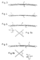
- Figures 3 and 4 show the arrangement of the cover ply 5 radially outside the breaker arrangement 4.
- the cover ply 5 surrounds the breaker arrangement 4 over its entire width, whereas in Figure 4 only the edge regions of the breaker arrangement 4 are surrounded by the cover ply 5 which is now a two-piece cover ply.
- the cover ply 5 is, in contrast to Figures 3 and 4, formed as a helically wound strip bandage (JLB), with the winding of the strip bandage 13 taking place from left to right in Figure 5 and from right to left in Figure 6 as is indicated in Figures 5b and 6b by the bandage part piece 10 by the arrows 11 and 12 respectively.
- JLB helically wound strip bandage
- the cover ply 5 is formed as a twin ply and is folded once wither in the left or in the right edge region of the breaker ply 4.
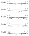
- the cover ply 5 shown in Figures 31 and 32 is formed as a helically wound strip bandage 13.
- Figures 33 and 34 show a cover ply 5 which in each case covers over a breaker arrangement 4 with differently formed breaker plies.
- the radially outer breaker ply is formed in two parts with a gap lying in the central axial region of the tyre.
- it is the radially inner breaker ply which is formed in two parts and has such a gap.
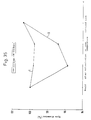
- the diagram of Figure 35 shows the effect which can be achieved with a cover ply 5 in accordance with the invention.
- the change of the tyre diameter of a pneumatic vehicle tyre with textile breaker plies is shown and indeed, firstly, for a tyre in accordance with the invention with a strip bandage with rayon cords (curve I) and secondly for a tyre with a strip bandage of nylon cords (curve II).
- the tyre diameter is shown at various stages of the tyre manufacture as well as for the completed tyre at room temperature and when pumped up.
- the tyre diameter is given here as a percentage of the diameter of the green tyre.
- the tyre diameter reduces by a considerably amount during vulcanisation due to the thermal shrinkage of the nylon.
- the tyre first reaches approximately the diameter of the tyre with a rayon cover ply when pumped up.
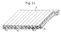
- the strip bandage 13 can be cut off from a rubberised ply 15 from which the cut breaker plies of the breaker arrangement 4 are also manufactured.
- a rubberised ply 15 of this kind is shown in Figure 36.
- the rubberised ply 15 has cords 16 which extend parallel to one another and which are formed in the illustrated example of two or three threads 17 which are twisted together.
- the cords 16 are enveloped with a caoutchouc mixture which was selected in accordance with the desired characteristics of the rubberised ply.
- the rubberised ply 15 however normally contains only cords 16 of two threads 17 or only cords 16 of three threads 17.
- Figure 36 thus only serves to illustrate various possibilities.
- the cords 16 of the rubberised ply 15 can for example consist of two aramid threads which are twisted together and the titre of which amounts to 1670 dtex.
- the cord density in the rubberised layer 15 can preferably amount to between 70 and 120 cords per 10 centimetres.
- the strips for the strip bandage 13 can be cut off from the marginal regions of the rubberised layer 15.
- the remaining part of the rubberised layer 15 is then used for the cut breaker plies of the breaker arrangement 4, with the remaining part of the rubberised ply 15 being cut for this purpose into individual cut breaker plies at an angle which corresponds to the desired cord angle of the respective cut breaker ply relative to the mid-circumferential plane 14.
- FIG. 37 A further possible layout of the cover ply 5 is shown in Figure 37.
- the cover ply 5 is formed in each of the two shoulder regions 18 by a respective helically wound strip bandage 19 and 20 respectively, and in the central tyre region 21 lying between them by a broad band 22.
- the two strip bandages 19 and 20 preferably have threads or cords of aramid, while the broad band 22 is provided with threads or cords of rayon.
- the individual windings of the strip bandage 19 and 20 can also be arranged abutting one another or overlapping one another, other than in the schematic illustration of Figure 37.
- the two strip bandages 19 and 20 can be respectively arranged abutting the broad band 22 or can overlap the latter, with the strip bandages 19 and 20 or the broad band 22 being arranged radially outwardly as desired.
- a strip bandage 23 is also provided as the cover ply 5 in the central region 21 of the tyre, in addition to the two strip bandages 19 and 20 in the two shoulder regions 18 of the tyre.
- the individual turns of the strip bandages 19 and 20 can be wound abutting or overlapping one another in a manner different from that illustrated.
- the individual turns of the strip bandage 23 present in the central region of the region 21 of the tyre can be arranged abutting or overlapping one another in a different manner from that illustrated.
- the turns of the strip bandage 19 or 20 adjacent to the strip bandage 23 can respectively overlap the adjacent turns of the strip bandage 23 or can be overlapped by the latter or be wound abutting the latter. It is, however, also possible to place the start of the strip bandage 23 directly at the confronting end of the strip bandage 19 and to place the start of the strip bandage 20 directly at the end of the strip bandage 23. In this manner, a particularly uniform cover ply 5 arises.
- the threads or cords of the strip bandages 19 and 20 also preferably consist of aramid in this variant, whereas the threads or cords of the strip bandage 23 are again preferably formed of rayon.
- a breaker arrangement 4 has in both variants preferably threads or cords or aramid. In this way, a particularly light and strong breaker arrangement is achieved.
- the cover ply 5 is preferably so designed that under the condition which exists during tyre manufacture, in particular with the usual pressure during shaping of approximately 20 bar, a maximum extension of ca. 0.1 to 0.5%, in particular 0.3£ is possible in the two shoulder regions 18 of the tyre, whereas in the central tyre region 21 a possible extension is set in the range from 2 to 3%, in particular 2.5 to 2.7%.
- a particularly firm covering over of the breaker arrangement 4 is achieved.
- this choice moreover counteracts further extension so that in the finished tyre a good strength of the breaker arrangement 4 is also given in the central region 21 of the tyre.
- the regions of the cover ply 5 with aramid threads or cords can in all embodiments cover over the breaker arrangement 4 from approximately 10% up to approximately 35 to 40%.
- the central region of the tyre accordingly extends ca. 60 to 90% of the breaker arrangement 4.
- the invention therefore allow a light tyre to be manufactured in an inexpensive manner which fulfils all the requirements for a modern tyre.
Abstract
Description
- The invention relates to a pneumatic vehicle tyre comprising a single ply or multi-ply radial carcass anchored to bead rings, a tread, a breaker arrangement provided between the carcass and the tread, the breaker arrangement preferably being built up of at least two cut breaker plies with the threads or cords of the breaker plies, which serve as strength carriers and extend parallel to one another in the respective layer, crossing at a predeterminable angle to the mid-circumferential plane and also comprising at least one cover ply of cords of threads extending at least substantially in the circumferential direction of the tyre and surrounding the breaker arrangement at least in its edge regions.
- Whereas the radial carcass forms the support construction of the tyre and gives strength to the tyre, the breaker arrangement provided between the carcass and the tread, which consists of at least two cut breaker plies, serves to give the pneumatic vehicle tyre the desired driving characteristics, in particular the necessary stability. In order to prevent separation of the breaker arrangement, in particular at high speeds, this separation predominantly occurring in the edge regions of the breaker lies, the breaker arrangement is, at least in this region, covered over with a cover or bandage layer having threads or cords which extend at least substantially in the circumferential direction of the tyre.
- Pneumatic vehicle tyres of the named kind are customarily manufactured using a cylindrical drum by laying the individual tyre components, such as the carcass and sidewalls, one after the other onto the drum. After the bead rings have been set in place and the carcass turned over around the, the tyre blank is then shaped to a toroid, the breaker plies applied to the tread and then the assembly is placed in a tyre mould in which the tyre profile is formed and the tyre is vulcanised.
- In order to finally shape the tyre blank into the tyre mould, the individual components of the tyre must be extensible in order to allow the final stretch of the tyre into the tyre mould.
- On the other hand, an extension of the tyre under static or dynamic loading should be avoided as far as possible in the finished tyre. While the breaker plies permit an extension to the requisite degree as a result of their cords which are arranged in a crossed arrangement at a predeterminable angle to the mid-circumferential plane, this can only be achieved for the cover or bandage ply, with its cords which extend substantially in the circumferential direction of the tyre, through a suitable choice of the cord material. However, in this respect account should additionally be taken of the fact that the cover or bandage ply serves to prevent a separation of the breaker arrangement. Despite the extensibility required for the formation of the tyre, the cover or bandage ply must therefore have adequate strength.
- Nowadays, breaker plies customarily contain steel cords as reinforcing elements, whereas the cover ply comprises nylon cords. However, the use of steel cords in the breaker arrangement is disadvantageous having regard to the increasing endeavour to reduce tyre weight.
- The invention is thus based on the object of further development a pneumatic vehicle tyre of the initially named kind so that its weight is reduced as much as possible without impairing the required characteristics of the pneumatic vehicle tyre.
- This object is satisfied in that the threads or cords of the breaker arrangement are threads or cords of non-metallic material; in that a material with low thermal shrinkage or no thermal shrinkage is used as the material for the threads or cords of the cover ply; and in extension of the tyre is ensured intc the tyre mould during its manufacture, through the choice of the material of the threads or cords of the cover ply alone, or in conjunction with the nature cf the build-up and/or of the application of the cover ply and/or through the nature of the build-up of the threads or cords of the cover ply, but with an extension of the tyre which goes beyond this being simultaneously counteracted.
- As a result of the use of non-metallic reinforcing elements instead of steel in the breaker arrangement, the tyre weight is advantageously reduced. In order to nevertheless give the tyre the desired properties, the cover ply is formed in the given manner.
- The choice is thus made so that the extension of the green tyre necessary for moulding the green tyre into the tyre mould is possible; so that no shrinkage of the tyre occurs on heating up of the completed tyre after vulcanisation, or during use; and so that extension of the tyre under static load (air pressure) or dynamic load (centrifugal force) is counteracted with a force which is as large as possible in order to prevent an undesired growth of the tyre.
- In contrast to a pure steel radial tyre, there is the problem, when non-metallic reinforcing elements are used in the breaker arrangement, that the breaker material has no or only a small bulk modulus. A shrinkage of the cover ply as a result of warming would therefore lead to a deformation of the tyre and thus to a worsening of the tyre properties up to its destruction.
- In accordance with the invention, a material for the threads of cords of the cover ply is preferred which has a modulus of elasticity which is as large as possible, at least in the initial range of tyre extension, but which still just permits an extension of the tyre into the mould during manufacture. An undesired extension of the tyre during use is thereby substantially prevented.
- Rayon has proved to be a particularly suitable material for the thread or cords of the cover plies. Rayon has a comparably high initial modulus, particularly in comparison to nylon, i.e. a relatively steep gradient of the stress-strain curve (force-extension curve) which is large enough to counteract an undesired extension of the tyre but which permits an extension of the tyre into the tyre mould. Moreover, rayon is practically free of thermal shrinkage.
- Polyester may also be used for the threads or cords of the cover ply providing that its modulus of elasticity is sufficiently large and its thermal shrinkage sufficiently small. High-modulus-low-shrinkage polyesters (HMLS) of this kind are already tested.
- Furthermore, threads or cords or aramid, or of a hybrid material with aramid, have proved to be advantageous for the cover ply. Aramid and the name hybrid materials are characterised by a particularly high tensile strength and thus prevent undesired tyre growth under static or dynamic loading. In this way, the tyre of the invention has particularly good fast running characteristics.
- The extension of the tyre necessary for the forming of the tyre tread or profile can be set via the build-up of the cover ply, in particular via the titre, i.e. the weight related to a specific length, of the threads or cords and their density in the respective ply, via the degree of twist of the cords and via the type of winding of the cover ply. Thus, the extensibility of the tyre increases with reducing thread density and reducing titre. In the same way the extensibility of the cords can be increased by a higher twist. Finally, the winding density and strength of the cover ply also co-determine the extensibility of the tyre.
- It has surprisingly turned out that when using these measures, even when using high modulus materials, in particular aramid materials, no problems arise during forming of the tyre profile.
- In any case, the threads or cords of the cover ply are preferably selected to be as thin as possible and as thick as necessary. The weight of the cover ply and thus the tyre weight can be reduced in this way.
- In a further embodiment of the invention, the breaker arrangement contains cords or threads of textile material, in particular or aramid. Aramid has a particularly high strength combined with a low weight. In comparison to steel, the weight can be significantly reduced. Particularly good tyre properties are achieved by the combination of an aramid breaker and a rayon cover ply. In place of aramid, glass fibres or carbon fibres can also be used in the breaker arrangement.
- In place of aramid, rayon or HMLS polyester can be used for the reinforcement elements of the breaker arrangement. Good tyre properties also result from this approach.
- In accordance with a further embodiment of the invention, the geometrical arrangement of the cover ply and/or the thread or cord density in the cover ply are used in addition to the selection of the cord or thread material of the cover ply for achieving the desired extension behaviour of the tyre.
- For example, the cover ply can be provided only in the edge regions of the breaker arrangement where the danger of separation of the breaker arrangement is the highest. Through this arrangement of the cover ply, the extension of the tyre into the tyre mould in the central axial region is practically unimpaired by the cover ply.
- With a cover ply which surround the breaker arrangement over its entire width, the threads or cords of the cover ply in the shoulder region of the tyre can consist of a material which is essentially non-extensible. In the middle tyre region disposed between the two shoulder regions the threads or cords of the cover ply can consist of a material which permits an extension of the tyre by a predeterminable amount under the conditions which prevail during tyre manufacture, but can oppose an extension of the tyre which goes beyond this with the largest possible resistance.
- Through this differential choice of material for the threads or cords of the cover ply in the shoulder region, on the one hand, and in the central tyre region, on the other hand, the extension of the tyre which is necessary for the arching of the tyre blank and for the formation of the tyre is made possible and the shoulder regions which are particularly endangered by separation effects are strengthened. The use of an essentially inextensible cord material in the shoulder regions is possible because the tyre extension which required here is very low. In the central tyre region where a considerable tyre extension is necessary a larger extension is made possible by a suitable choice of material. Through adjustment of the permissible extension to the degree required during tyre manufacture an extension of the finished tyre beyond this dimension can be largely prevented.
- Aramid has turned out to be a particularly suitable material for the threads and cords in the shoulder region of the cover ply and rayon for the threads or cords of the cover ply in the central region of the tyre. Whereas aramid has only a very low extensibility, rayon permits an extension up to a certain degree but generates a large restraining force for an extension which goes beyond this. The finished tyre thereby becomes particularly stable.
- The cover ply can be formed in the shoulder regions of the tyre and/or in the central region of the tyre by a helically wound strip bandage, a so-called jointless band (JLB). The cover ply in the central region of the tyre can also be formed as a broad band in accordance with one embodiment of the invention.
- The sections of the cover ply in the shoulder regions and in the central tyre region can be respectively arranged either abutting one another or overlapping one another. When using a strip bandage for both the two shoulder regions and also for the central tyre region, the single strips of different material can also be directly wound adjoining one another around the tyre, that is to say the start of the strip which is wound around the centre of the tyre is set at the end of the strip wound around the one shoulder region and the start of the strip wound around the second shoulder region is set at the end of the strip wound around the centre of the tyre. In this manner, a particular uniform cover ply is obtained and the tyre characteristics are improved.
- The permissible extension of the cover ply during the manufacture of the tyre can be restricted by choice of the cord material in the shoulder region to a maximum of ca. 0.1 to 0.5%, in particular to circa 0.3%, whereas in the central region of the tyre a permissible extension during manufacture, for example in the range between 2 to 3%, in particular 2.5 to 2.7%, can be set through the choice of the cord material. With this choice, particularly good tyre characteristics can be obtained.
- These extension relationships can be particularly advantageously set through the combination of aramid in the shoulder regions of the tyre, and rayon in the central tyre region as materials for the cords of the cover ply. The force-extension curves of aramid and rayon have a favourable relationship relative to each other for this purpose. That is to say, substantially the same sized forces are required in the shoulder region and in the central region of the tyre for the extension of the breaker with the cover ply during the moulding of the tyre with this choice of material, whereby a uniform moulding and harmonious tyre characteristics are achieved.
- Aramid is preferably used as a material for the threads or cords of the breaker arrangement with this layout of the invention. In this way, the tyre weight is kept low. In conjunction with rayon for the threads or cords of the cover ply in the central region of the tyre and aramid in the two shoulder regions of the tyre, one obtains a particularly advantageous tyre assembly with high strength and low weight. Through the use of rayon which has no thermal shrinkage it is ensured that during heating of the tyre no deformations arise as a result of the lacking bulk modulus of textile cut breaker plies. The combination of aramid in the shoulder region and rayon in the central region of the tyre could however basically also be used with steel breakers. The tyre weight would however then be higher.
- The extension behaviour of the cover ply, i.e. the modulus of elasticity of the cover ply as a whole, can be directly influenced by the thread or cord density. A high cord or thread density produces a high modulus of elasticity and, correspondingly, a small modulus of elasticity of the cover ply is produced by a small thread or cord density.
- A further possibility for influencing the extension behaviour of the cover ply through its construction is to alter the winding density and/or the winding strength in order to adjust the extension behaviour of the cover ply, i.e. its modulus of elasticity, in a deliberate manner. A large modulus of elasticity of the cover ply can thus be set by a high winding density and/or by a high winding strength whereas, correspondingly, a small modulus of elasticity can be set by a small winding density and/or winding strength.
- In accordance with a further embodiment of the invention, the winding density and/or winding strength are selected differently across the width of the tyre, with them being preferably selected to be respectively higher or larger in the edge regions of the breaker arrangement. This allows the desired extension behaviour, and, in general, the desired properties of the tyre to be taken into account particularly well.
- As already described, a high modulus of elasticity is necessary in the edge regions of the breaker plies, which correspond to the shoulder regions of the tyre, in order to counteract the particularly large danger of separation of the breaker plies here, whereas in the central axial region of the tyre a smaller modulus of elasticity of the cover ply is sufficient.
- In accordance with a further embodiment of the invention, the setting of the desired extension properties cf the cover ply can be achieved via the build-up of the cords or threads of the cover ply by a corresponding selection of the degree of twist of these threads or cords. The cords or threads are given an additional elasticity by increasing their degree of twist in the cover ply thus leading to a reduction of the modulus of elasticity of the cover ply. On the other hand, a larger modulus of elasticity can be produced by a reduced degree of twist.
- In order to set the desired extension behaviour further, measures have proved to be particularly suitable. Thus, the cover ply can cover over the entire breaker ply or only a part of it, in particular the two edge regions of the breaker plies. In the first case in particular, the cover ply can alsc be constructed as a singly-folded twin-ply.
- In a cover ply made of helically wound strips, a so-called JLB (jointless band), the individual strip windings can overlap one another and the width of overlap can be selected to be different over the width of the tyre. In this manner the extension properties can also be varied in a controlled manner over the width of the tyre. In particular, a large modulus of elasticity of the cover ply can be provided in the shoulder regions of the tyre, whereas a small modulus of elasticity can be provided in the central axial region of the tyre. This can, for example, be achieved by providing an overlap of the strip windings only in the regions which cover over the two edge regions of the breaker arrangement, or by making this overlap particularly large here.
- The winding sense and winding direction of the strip bandage can, in accordance with the further embodiments of the invention, also be different over the width of the tyre. In particular, the winding sense and winding direction on one side of the mid-circumferential plane can be opposite to that on the other side of the mid-circumferential plane. This also allows the tyre properties to be influenced in a controlled manner.
- In summary, the modulus of elasticity of the cover ply can be adjusted in a controlled manner by using the various measures described above, that is to say, the stress-strain curve (force extension) of the cover ply can be given a desired characteristic.
- Moreover, the breaker arrangement can also be designed in different ways. In particular one or more of the breaker plies can have a multi-part construction, for instance with a gap in the central axial region. The type and construction of the reinforcing elements of the breaker arrangement can also be used to influence the extension properties of the tyre in a similar manner as for the cover ply.
- Furthermore, the breaker arrangement can consist, in accordance with the invention, either exclusively of non-metallic breaker plies or can consist of both non-metallic and steel breaker plies (so-called hybrid construction). In both cases the cover ply design in accordance with the invention has a favourable effect on the tyre properties.
- In accordance with a further layout of the invention, cords or threads of the same material and with the same titre are used in the breaker plies and in the cover ply. Through this layout, the storage of materials is made easier and more cost-favourable since only one particular cord need be kept available for each type of tyre.
- Cords consisting of two twisted aramid threads with a titre of respectively 1670 dtex., i.e. grams per 10,000 metres, and also a cord density in the breaker plies of ca. 70 to 120 cords per 10 centimetres and in the cover ply of ca. 60 to 90 cords per 10 centimetres have proved to be particularly suitable, with the breaker arrangement preferably being built-up of two aramid breaker plies and one aramid strip bandage serving as the cover ply.
- In accordance with a further embodiment of the invention, the cord density in the breaker plies and in the strips of the cover ply are of the same size. This layout has the advantage that the breaker plies and the strips for the cover ply can be manufactured from a single rubberised ply. A rubberised ply can thus also be manufactured with the desired cords at the required cord density in the form of an endless band from which then both the breaker plies and also the strips for the cover ply can be cut off. In this way, the manufacturing of the tyre of the invention is simplified.
- A particularly favourable method for the manufacturing of such a pneumatic vehicle tyre lies in first manufacturing a rubberised ply with textile cords at the required cord density and in that the strips required for the cover ply are cut-away from this ply at the side margins, whereas the remaining part of the rubberised ply is used for the breaker plies. In this way, a rubberised ply can be manufactured as a continuous band from which then both the strips for the cover ply and also the breaker plies can be cut off. The manufacture is thereby made particularly simple and practically no cutting losses arise.
- Embodiments of the invention are shown in the Figures and are described in the following.
- They show:
- Figure 1 a cross-section through a pneumatic vehicle tyre in accordance with the invention;
- Figure 2 a perspective partial view of a sectioned tyre in accordance with the invention;
- Figures 3 to 34 various variants of the cover ply in accordance with the invention shown schematically;
- Figure 35 a strain or extension diagram of tyres with textile breaker plies and with various cover plies in comparison;
- Figure 36 a perspective illustration of a rubberised ply for use in the tyre in accordance with Figure 1;
- Figure 37 a schematic illustration of a first variant of a breaker and cover ply arrangement in accordance with the invention to a scale reduced relative to Figure 1; and
- Figure 38 a further variant of a breaker and cover ply arrangement in accordance with the invention in an illustration corresponding to Figure 37.
- The tyre shown in Figure 1 has a
radial carcass 2 anchored to the bead rings 1, atread 3 and a breaker arrangement 4 comprising two breaker plies positioned between thecarcass 2 and thetread 3, as well as acover ply 5 surrounding the breaker arrangement. The bead rings 1 are each provided with abead core 6 on which a bead filler orbead apex 7 is arranged. - It can be seen from Figure 2 that both the breaker plies of the breaker arrangement 4 and also the cover ply 5 comprise mutually parallel cords or
threads 8 and 9 respectively in the respective ply. Whereas the cords orthreads 8 of the cover ply 5 extend substantially in the circumferential direction of the tyre, the cords or threads 9 of the two breaker plies 4 of the breaker arrangement cross each other at a particular angle relative to the central circumferential plane of the tyre. - Figures 3 and 4 show the arrangement of the cover ply 5 radially outside the breaker arrangement 4. In Figure 3 the cover ply 5 surrounds the breaker arrangement 4 over its entire width, whereas in Figure 4 only the edge regions of the breaker arrangement 4 are surrounded by the cover ply 5 which is now a two-piece cover ply.
- In Figures 5 and 6, the cover ply 5 is, in contrast to Figures 3 and 4, formed as a helically wound strip bandage (JLB), with the winding of the
strip bandage 13 taking place from left to right in Figure 5 and from right to left in Figure 6 as is indicated in Figures 5b and 6b by thebandage part piece 10 by thearrows - In Figures 7 and 8 an embodiment is shown in which the individual windings of the
strip bandage 13 overlap, with the winding direction corresponding on the one hand to that of Figure 5 and on the other h and to that of Figure 6. - In the Figures 9 and 10, the winding direction on the left and the right of the central circumferential plane 14 is in each case different. Otherwise, these embodiments correspond to those of Figures 7 and 8.
- In Figures 11 to 16, the overlap between the individual windings of the
bandage strip 13 is different over the width of the tyre. In Figures 11 to 14 an overlap only occurs in the edge regions of the breaker arrangement 4 and thestrip bandage 13 is wound in the central axial region in abutting form or with gaps. In contrast, in Figures 15 and 16 an overlap occurs over the entire width of the tyre, this overlap being larger in the edge regions of the breaker arrangement 4 than in the central axial regior of the tyre. The winding direction is in each case different as is indicated with thearrows - In Figures 17 to 28, the cover ply 5 is only provided in the edge regions of the breaker arrangement 4. In Figures 17 to 20 each of the individual turns overlap and the winding direction is that indicated by the
arrows arrows - In Figures 29 to 32, the cover ply 5 is formed as a twin ply and is folded once wither in the left or in the right edge region of the breaker ply 4. Although in Figures 29m and 30 the cover ply 5 is formed as a broad band, the cover ply 5 shown in Figures 31 and 32 is formed as a helically
wound strip bandage 13. - Figures 33 and 34 show a
cover ply 5 which in each case covers over a breaker arrangement 4 with differently formed breaker plies. In Figure 33 the radially outer breaker ply is formed in two parts with a gap lying in the central axial region of the tyre. In contrast, in Figure 34, it is the radially inner breaker ply which is formed in two parts and has such a gap. - The diagram of Figure 35 shows the effect which can be achieved with a
cover ply 5 in accordance with the invention. The change of the tyre diameter of a pneumatic vehicle tyre with textile breaker plies is shown and indeed, firstly, for a tyre in accordance with the invention with a strip bandage with rayon cords (curve I) and secondly for a tyre with a strip bandage of nylon cords (curve II). The tyre diameter is shown at various stages of the tyre manufacture as well as for the completed tyre at room temperature and when pumped up. The tyre diameter is given here as a percentage of the diameter of the green tyre. - One can see that with a tyre in accordance with the invention with a rayon cover ply (curve I) the tyre diameter remains almost unchanged throughout tyre production. On pumping the tyre up, its circumference increases by a small amount.
- For a tyre with a nylon cover ply (curve II) the tyre diameter reduces by a considerably amount during vulcanisation due to the thermal shrinkage of the nylon. The tyre first reaches approximately the diameter of the tyre with a rayon cover ply when pumped up.
- The
strip bandage 13 can be cut off from arubberised ply 15 from which the cut breaker plies of the breaker arrangement 4 are also manufactured. Arubberised ply 15 of this kind is shown in Figure 36. Therubberised ply 15 hascords 16 which extend parallel to one another and which are formed in the illustrated example of two or threethreads 17 which are twisted together. Thecords 16 are enveloped with a caoutchouc mixture which was selected in accordance with the desired characteristics of the rubberised ply. Therubberised ply 15 however normally contains onlycords 16 of twothreads 17 or onlycords 16 of threethreads 17. Figure 36 thus only serves to illustrate various possibilities. - The
cords 16 of therubberised ply 15 can for example consist of two aramid threads which are twisted together and the titre of which amounts to 1670 dtex. The cord density in therubberised layer 15 can preferably amount to between 70 and 120 cords per 10 centimetres. - The strips for the
strip bandage 13 can be cut off from the marginal regions of therubberised layer 15. The remaining part of therubberised layer 15 is then used for the cut breaker plies of the breaker arrangement 4, with the remaining part of therubberised ply 15 being cut for this purpose into individual cut breaker plies at an angle which corresponds to the desired cord angle of the respective cut breaker ply relative to the mid-circumferential plane 14. - A further possible layout of the cover ply 5 is shown in Figure 37. Here the cover ply 5 is formed in each of the two
shoulder regions 18 by a respective helically woundstrip bandage central tyre region 21 lying between them by abroad band 22. The twostrip bandages broad band 22 is provided with threads or cords of rayon. - The individual windings of the
strip bandage strip bandages broad band 22 or can overlap the latter, with thestrip bandages broad band 22 being arranged radially outwardly as desired. - In the variant illustrated in Figure 38 a
strip bandage 23 is also provided as the cover ply 5 in thecentral region 21 of the tyre, in addition to the twostrip bandages shoulder regions 18 of the tyre. With this layout, the individual turns of thestrip bandages strip bandage 23 present in the central region of theregion 21 of the tyre can be arranged abutting or overlapping one another in a different manner from that illustrated. - The turns of the
strip bandage strip bandage 23 can respectively overlap the adjacent turns of thestrip bandage 23 or can be overlapped by the latter or be wound abutting the latter. It is, however, also possible to place the start of thestrip bandage 23 directly at the confronting end of thestrip bandage 19 and to place the start of thestrip bandage 20 directly at the end of thestrip bandage 23. In this manner, a particularly uniform cover ply 5 arises. - The threads or cords of the
strip bandages strip bandage 23 are again preferably formed of rayon. A breaker arrangement 4 has in both variants preferably threads or cords or aramid. In this way, a particularly light and strong breaker arrangement is achieved. - The cover ply 5 is preferably so designed that under the condition which exists during tyre manufacture, in particular with the usual pressure during shaping of approximately 20 bar, a maximum extension of ca. 0.1 to 0.5%, in particular 0.3£ is possible in the two
shoulder regions 18 of the tyre, whereas in the central tyre region 21 a possible extension is set in the range from 2 to 3%, in particular 2.5 to 2.7%. Through this choice, it is possible to ensure the extension required for the shaping into the tyre mould of the tyre blank built up on the cylindrical building drum in themiddle tyre region 21, whereas in theshoulder regions 18, where practically no extension is necessary, a particularly firm covering over of the breaker arrangement 4 is achieved. In themid-region 21 of the tyre this choice moreover counteracts further extension so that in the finished tyre a good strength of the breaker arrangement 4 is also given in thecentral region 21 of the tyre. - The regions of the cover ply 5 with aramid threads or cords can in all embodiments cover over the breaker arrangement 4 from approximately 10% up to approximately 35 to 40%. The central region of the tyre accordingly extends ca. 60 to 90% of the breaker arrangement 4.
- The invention therefore allow a light tyre to be manufactured in an inexpensive manner which fulfils all the requirements for a modern tyre.
- Further variations of the construction of the
cover ply 5, of the arrangement of the cover ply 5 on the breaker ply 4 as well as of the materials used is of course possible within the scope of the invention. What always matters is to adjust the stress-strain (force-extension) curve of the cover ply 5 by varying the parameters indicated so that the desired extension behaviour of the tyre is achieved, i.e. one which, on the one hand, allows the tyre to be manufactured in a satisfactory manner with a clean formation of the tyre profile and, on the other hand, results in optimum tyre properties.
Claims (19)
- A pneumatic vehicle tyre comprising a single ply or multi-ply radial carcass anchored to bead rings, a tread, a breaker arrangement provided between the carcass and the tread, the breaker arrangement preferably being built up of at least two cut breaker plies with the threads or cords of the cut breaker plies, which serve as strength carries and extend parallel to one another in the respective layer, crossing at a predeterminable angle to the central mid-circumferential plane, and also comprising at least one cover ply of cords or threads extending at least substantially in the circumferential direction of the tyre and surrounding the breaker arrangement at least in its edge regions, characterised in that the breaker arrangement (4) has threads or cords (9) of non-metallic material; in that a material with a low thermal shrinkage or no thermal shrinkage is used as the material for the threads or cords (8) of the cover ply (5); and in that extension of the tyre into the tyre mould during its manufacture is ensured through the choice of the material of the threads or cords of the cover ply (5) alone, or in conjunction with the nature of the construction and/or of the application of the cover ply (5) and/or through the nature of the construction of the threads or cords (8) of the cover ply (5), but extension of the tyre which goes beyond this being simultaneously counteracted.
- A pneumatic vehicle tyre in accordance with claim 1, characterised in that a material with the largest possible initial modulus of elasticity is used as the material for the threads or cords (8) of the cover ply (5) and only just permits an extension of the tyre into the tyre mould during manufacture.
- A pneumatic vehicle tyre in accordance with claim 1 or claim 2, characterised in that the cover ply (5) has threads or cords (8) of rayon, or of a polyester with a high modulus of elasticity and low thermal shrinkage, so-called HMLS polyester, or of aramid or of a hybrid material with aramid.
- A pneumatic vehicle tyre in accordance with one of the preceding claims, characterised in that the degree of twisting of the threads or cords (8) of the cover ply (5) and/or the geometrical arrangement of the cover ply (5) and/or the thread density or cord density in the cover ply (5) and/or the winding density and/or winding strength of the cover ply (5) and/or the nature of the construction of the breaker arrangement (4), in particular the nature of the construction of the threads or cords (9) of the breaker arrangement (4) are at least also used to set the desired extension behaviour.
- A pneumatic vehicle tyre in accordance with one of the preceding claims, characterised in that the winding density and/or winding strength of the cover layer (5) are selected to be different in the axial direction of the tyre and are in particular respectively higher or greater in the edge regions of the breaker arrangement (4).
- A pneumatic vehicle tyre in accordance with one of the preceding claims, characterised in that the cover ply (5) is formed as a broad band which can also be formed by simple folding as a double ply.
- A pneumatic vehicle tyre in accordance with one of the claims 1 to 5, characterised in that the cover ply (5) is formed as a helically wound strip bandage, with adjacent windings of the strip bandage (13) preferably overlapping at least in part, and indeed in particular only in the two regions of the cover ply (5) which cover over the two edge regions of the breaker arrangement (4), and with the width of overlap being selectable to differ over the width of the tyre.
- A pneumatic vehicle tyre in accordance with claim 7, characterised in that the sense of winding and/or the winding direction of the strip bandage (13) are different in the axial direction of the tyre, and are in particular respectively opposite on one side of the mid-circumferential plane (I) to that on the other side of the mid-circumferential plane (I).
- A pneumatic vehicle tyre in accordance with one of the preceding claims characterised in that no cover is present in the axially central region of the tyre and in particular only the two edge regions of the breaker arrangement (4) are covered over.
- A pneumatic vehicle tyre in accordance with one of the claims 1 to 8, characterised in that the cover ply (5) surrounds the breaker arrangement (4) over its entire width, with the threads or cords of the cover ply (5) in the two shoulder regions (18) of the tyre preferably consisting of a material which is essentially non-extensible, preferably aramid, and consisting in the central tyre region (21) disposed between the two shoulder regions (18) of a material, preferably rayon, which permits an extension of the tyre by a predeterminable amount under the conditions which are present during tyre manufacture, but oppose an extension of the tyre which goes beyond this with a resistance which is as large as possible.
- A pneunatic vehicle tyre in accordance with claim 10, characterised in that a helically wound strip bandage (19,20 and 23) serves as the cover ply (5) in the shoulder regions (18) and in the central tyre region (21).
- A pneumatic vehicle tyre in accordance with claim 10, characterised in that the cover ply (5) is formed as a helically wound strip bandage (19,20) in the shoulder regions and as a broad band (22) in the central tyre region (21).
- A pneumatic vehicle tyre in accordance with one of the preceding claims, characterised in that the cover ply (5) in the two shoulder regions (18) of the tyre is respectively arranged abutting the cover layer (5) in the central region (21) of the tyre, or overlapping the latter.
- A pneumatic vehicle tyre in accordance with one of the preceding claims, characterised in that the cover ply (5) in the shoulder region (18) has an extensibility of at most ca. 0.1 to 0.5%, in particular ca. 0.3% and an extensibility in the central region (21) of the tyre in the range from 2 to 3%, in particular ca. 2.5 to 2.7%.
- A pneumatic vehicle tyre in accordance with any one of the preceding claims, characterised in that the breaker arrangement (4) has threads or cords (9) of textile material, in particular of aramid or rayon or of HMLS polyester, or of glass fibre or of carbon fibre.
- A pneumatic vehicle tyre in accordance with one of the preceding claims, characterised in that threads or cords (16) of the same material and with the same titre, i.e. weight related to a particular length, are used for the breaker arrangement (4) and for the ccver ply (5), with the cord density preferably being the same in the individual breaker plies of the breaker arrangement (4) and in the cover ply (5).
- A method of manufacturing a pneumatic vehicle tyre in accordance with claim 15, characterised in that the breaker arrangement (4) has two aramid breaker plies and in that an aramid strip bandage is provided as the cover ply (5).
- A pneumatic vehicle tyre in accordance with claim 16 or 17, characterised in that cords (16) of two twisted together aramid threads (17), each having a titre of 1670 dtex, i.e. grams per 10,000 metre, are used for the breaker arrangement (4) and the cover ply (5), in that the cord densities in the individual breaker plies of the breaker arrangement (4) amount to approximately 70 to 120 cords per 10cm, and in that the cord density in the cover ply (5) amounts to approximately 60 to 90 cords per 10cm.
- A method of manufacture of a pneumatic vehicle tyre in accordance with claim 16, characterised in that initially a rubberised ply (15) comprising textile cords (16) is manufactured with the desired cord density, and in that the strips required for the cover ply (5) are cut off from the edge of the rubberised ply (15), whereas the remaining part of the rubberised ply (15) is used for the individual plies of the breaker arrangement (4).
Applications Claiming Priority (6)
| Application Number | Priority Date | Filing Date | Title |
|---|---|---|---|
| DE4429899 | 1994-08-23 | ||
| DE19944429899 DE4429899A1 (en) | 1994-08-23 | 1994-08-23 | Pneumatic tyre breaker for light tyres |
| DE19506381 | 1995-02-23 | ||
| DE1995106381 DE19506381A1 (en) | 1994-08-23 | 1995-02-23 | Pneumatic tyre breaker for light tyres |
| DE19509824 | 1995-03-17 | ||
| DE1995109824 DE19509824A1 (en) | 1995-03-17 | 1995-03-17 | Pneumatic tyre breaker for light tyres |
Publications (3)
| Publication Number | Publication Date |
|---|---|
| EP0698510A2 true EP0698510A2 (en) | 1996-02-28 |
| EP0698510A3 EP0698510A3 (en) | 1996-04-10 |
| EP0698510B1 EP0698510B1 (en) | 1999-04-28 |
Family
ID=27206693
Family Applications (1)
| Application Number | Title | Priority Date | Filing Date |
|---|---|---|---|
| EP95305805A Expired - Lifetime EP0698510B1 (en) | 1994-08-23 | 1995-08-21 | Pneumatic vehicle tyre |
Country Status (4)
| Country | Link |
|---|---|
| US (1) | US5795417A (en) |
| EP (1) | EP0698510B1 (en) |
| JP (1) | JP3145902B2 (en) |
| DE (1) | DE69509323T2 (en) |
Cited By (14)
| Publication number | Priority date | Publication date | Assignee | Title |
|---|---|---|---|---|
| WO1998056599A1 (en) * | 1997-06-09 | 1998-12-17 | The Goodyear Tire & Rubber Company | Light weight fiberglass belted radial tire |
| WO1998056600A1 (en) * | 1997-06-09 | 1998-12-17 | The Goodyear Tire & Rubber Company | Light weight aramid belted radial tire |
| WO1998056601A1 (en) * | 1997-06-09 | 1998-12-17 | The Goodyear Tire & Rubber Company | Low cost light weight radial tire |
| EP0974449A2 (en) * | 1998-07-21 | 2000-01-26 | BRIDGESTONE/FIRESTONE, Inc. | Band element for pneumatic tire and method of making same |
| EP0978396A2 (en) * | 1998-08-03 | 2000-02-09 | Continental Aktiengesellschaft | Vehicle tyre |
| WO2001003954A1 (en) * | 1999-07-09 | 2001-01-18 | Pirelli Pneumatici Spa | High performance tyre with tread band having an anisotropic underlayer stable upon temperature variation |
| EP1167003A2 (en) * | 2000-06-26 | 2002-01-02 | Sumitomo Rubber Industries, Ltd. | Method of making a pneumatic tire having a tread belt |
| WO2002007994A1 (en) * | 2000-07-24 | 2002-01-31 | Societe De Technologie Michelin | Tyre with aramid fibre protective crown ply |
| EP1207055A2 (en) * | 2000-11-09 | 2002-05-22 | Sumitomo Rubber Industries Ltd. | Pneumatic tire |
| WO2003086783A1 (en) * | 2002-04-08 | 2003-10-23 | Societe De Technologie Michelin | Pneumatic tire crown reinforcement |
| US6820666B2 (en) | 1998-10-28 | 2004-11-23 | Pirelli Pneumatici S.P.A. | Tire, including fiber-reinforced elastomeric intermediate layer between the belt structure and tread band, and method of making the tire |
| WO2005002884A1 (en) * | 2003-06-19 | 2005-01-13 | Pirelli Pneumatici S.P.A. | Tyre with improved belt structure |
| US7299843B2 (en) | 2002-04-08 | 2007-11-27 | Michelin Recherche Et Technique S.A. | Pneumatic tire crown reinforcement |
| EP3085818A1 (en) * | 2015-04-20 | 2016-10-26 | Continental Reifen Deutschland GmbH | Method for manufacturing vehicle tyres and vehicel tyre obtained thereby |
Families Citing this family (33)
| Publication number | Priority date | Publication date | Assignee | Title |
|---|---|---|---|---|
| US6460586B1 (en) | 2000-03-29 | 2002-10-08 | Bridgestone/Firestone North American Tire, Llc | Multi-region band element for run flat tire |
| US6321808B1 (en) | 2000-03-29 | 2001-11-27 | Bridgestone/Firestone Research, Inc. | Expandable band for run flat tire and method of making |
| US6405773B1 (en) | 2000-06-14 | 2002-06-18 | Bridgestone/Firestone North American Tire, Llc | Run flat pneumatic tire and band element therefor |
| US6470937B1 (en) | 2000-10-03 | 2002-10-29 | Bridgestone/Firestone North American Tire, Llc | Run flat pneumatic tire and anticlastic band element therefor |
| JP3993378B2 (en) * | 2000-11-01 | 2007-10-17 | 住友ゴム工業株式会社 | Pneumatic radial tire |
| US6439288B1 (en) | 2000-11-28 | 2002-08-27 | Bridgestone/Firestone North American Tire, Llc | Pneumatic tire with variable thickness band element |
| US6444070B1 (en) * | 2000-11-29 | 2002-09-03 | The Goodyear Tire & Rubber Company | Method of building a tire having a segmented belt |
| US7329459B2 (en) * | 2003-03-07 | 2008-02-12 | Performance Fibers, Inc. | Polymer-based reinforcement material and tire cord compositions and methods of production thereof |
| US7216684B2 (en) * | 2003-12-29 | 2007-05-15 | The Goodyear Tire & Rubber Company | Pneumatic aviation tire |
| JP4723198B2 (en) * | 2004-03-22 | 2011-07-13 | 住友ゴム工業株式会社 | Pneumatic tire |
| FR2875736A1 (en) * | 2004-09-24 | 2006-03-31 | Michelin Soc Tech | PNEUMATIC SYSTEM COMPRISING A PLURALITY OF ZONES FORMED WITH A CIRCUMFERENTIAL REINFORCING YARN |
| ES2304254T3 (en) * | 2004-12-16 | 2008-10-01 | Pirelli Tyre S.P.A. | PROCEDURE AND PLANT FOR THE MANUFACTURE OF TIRES FOR VEHICLE WHEELS. |
| DE102005018964A1 (en) * | 2005-04-23 | 2006-10-26 | Continental Aktiengesellschaft | Production of radial tyres, involves making the radial bracing belt by feeding reinforced binding material onto the lay-up drum from at least four winding heads and winding it round the belt by twisting the drum |
| US8505601B2 (en) * | 2005-05-31 | 2013-08-13 | The Yokohama Rubber Co., Ltd. | Pneumatic radial tire |
| US20070154510A1 (en) * | 2005-12-30 | 2007-07-05 | Wilcher Steve A | Adsorbent-Containing Hemostatic Devices |
| US20070154509A1 (en) * | 2005-12-30 | 2007-07-05 | Wilcher Steve A | Adsorbent-Containing Hemostatic Devices |
| JP2007307976A (en) * | 2006-05-17 | 2007-11-29 | Bridgestone Corp | Pneumatic tire and its manufacturing method |
| JP2008149992A (en) * | 2006-12-20 | 2008-07-03 | Bridgestone Corp | Pneumatic tire for two-wheeler |
| FR2916159B1 (en) * | 2007-05-14 | 2011-03-18 | Michelin Soc Tech | PNEUMATIC FOR HEAVY VEHICLES |
| FR2916160B1 (en) * | 2007-05-14 | 2009-07-17 | Michelin Soc Tech | PNEUMATIC FOR HEAVY VEHICLES |
| WO2009113583A1 (en) * | 2008-03-12 | 2009-09-17 | 本田技研工業株式会社 | Radial tire for vehicle and method for manufacturing the same |
| ATE550206T1 (en) * | 2008-05-28 | 2012-04-15 | Pirelli | MOTORCYCLE TIRES |
| US20100051164A1 (en) * | 2008-08-29 | 2010-03-04 | Robert Anthony Neubauer | Modular ply tire with dissimilar materials |
| FR2939723B1 (en) * | 2008-12-17 | 2010-12-31 | Michelin Soc Tech | PNEUMATIC VEHICLE COMPRISING A LAYER OF CIRCUMFERENTIAL REINFORCING ELEMENTS |
| JP5320201B2 (en) * | 2009-07-31 | 2013-10-23 | 株式会社ブリヂストン | Tire manufacturing method and tire |
| FR2962371B1 (en) * | 2010-07-07 | 2014-03-21 | Michelin Soc Tech | TOP REINFORCEMENT FOR AIR TIRE |
| JP5735810B2 (en) * | 2011-01-14 | 2015-06-17 | 株式会社ブリヂストン | Pneumatic tire and method for forming circumferential belt layer in pneumatic tire |
| CN104245357B (en) * | 2012-02-06 | 2016-12-07 | 株式会社普利司通 | Pneumatic belt tire |
| US20140174624A1 (en) * | 2012-12-21 | 2014-06-26 | Bridgestone Americas Tire Operations, Llc | Variable Belt Configuration |
| JP6450112B2 (en) * | 2014-08-15 | 2019-01-09 | 株式会社ブリヂストン | Pneumatic tire |
| DE102014220518A1 (en) * | 2014-10-09 | 2016-04-14 | Continental Reifen Deutschland Gmbh | Pneumatic vehicle tire having a belt bandage |
| DE102014222921A1 (en) * | 2014-11-11 | 2016-05-12 | Continental Reifen Deutschland Gmbh | Vehicle tires |
| DE102018206562A1 (en) * | 2018-04-27 | 2019-10-31 | Continental Reifen Deutschland Gmbh | Vehicle tires |
Citations (12)
| Publication number | Priority date | Publication date | Assignee | Title |
|---|---|---|---|---|
| FR792853A (en) * | 1934-07-23 | 1936-01-11 | Matador Gummiwerke Ag | Pneumatic tire for vehicles and the like |
| GB2064445A (en) * | 1979-12-06 | 1981-06-17 | Dunlop Ltd | Pneumatic Tyre Breakers |
| EP0235579A2 (en) * | 1986-03-04 | 1987-09-09 | Continental Aktiengesellschaft | Pneumatic tyre for a vehicle |
| US4887655A (en) * | 1986-06-20 | 1989-12-19 | Bridgestone Corporation | Heavy duty-high pressure pneumatic radial tires |
| JPH02141309A (en) * | 1988-11-22 | 1990-05-30 | Sumitomo Rubber Ind Ltd | Radial tire for heavy load |
| EP0407071A2 (en) * | 1989-06-30 | 1991-01-09 | Sumitomo Rubber Industries Limited | Heavy duty high speed radial tyre |
| EP0412928A2 (en) * | 1989-08-10 | 1991-02-13 | The Goodyear Tire & Rubber Company | Pneumatic tire |
| EP0455453A2 (en) * | 1990-05-02 | 1991-11-06 | Sumitomo Rubber Industries Limited | Radial tyre for a motorcycle |
| EP0561177A1 (en) * | 1992-03-19 | 1993-09-22 | Continental Aktiengesellschaft | Pneumatic vehicle tyre |
| DE4209817A1 (en) * | 1992-03-26 | 1993-09-30 | Uniroyal Englebert Gmbh | Radial pneumatic tyre - has cover fabric over running belt layer with high modulus near middle and lower modulus near shoulder |
| EP0571204A1 (en) * | 1992-05-20 | 1993-11-24 | Sp Reifenwerke Gmbh | Pneumatic vehicle tyre |
| EP0622252A1 (en) * | 1993-04-27 | 1994-11-02 | The Goodyear Tire & Rubber Company | Belt reinforcing structure for a pneumatic tire |
Family Cites Families (17)
| Publication number | Priority date | Publication date | Assignee | Title |
|---|---|---|---|---|
| US3774662A (en) * | 1971-07-08 | 1973-11-27 | Uniroyal Inc | Production of high soft stretch tapes of reinforcing cords for molded elastomeric articles |
| US3900062A (en) * | 1971-07-08 | 1975-08-19 | Uniroyal Inc | Zero degree belted tires built with high soft stretch belt-forming tapes |
| US3979536A (en) * | 1971-07-08 | 1976-09-07 | Uniroyal Inc. | Zero degree belted tires, and high "soft stretch" belt-forming tapes therefor |
| US4201260A (en) * | 1976-05-07 | 1980-05-06 | Uniroyal, Inc. | Method for making a radial ply tire in a single building stage |
| US4098315A (en) * | 1977-03-09 | 1978-07-04 | Uniroyal, Inc. | Belted pneumatic tires with zero degree breaker reinforcement, and method of building such tires |
| US4094354A (en) * | 1977-03-09 | 1978-06-13 | Uniroyal, Inc. | Breaker reinforcing tape for belted pneumatic tires, and tires made therefrom |
| DE3580076D1 (en) * | 1984-08-29 | 1990-11-15 | Sumitomo Rubber Ind | PLANE TIRES. |
| GB8708977D0 (en) * | 1987-04-14 | 1987-05-20 | Goodyear Tire & Rubber | Reinforcing plies for tyres |
| US5032198A (en) * | 1987-06-18 | 1991-07-16 | Sumitomo Rubber Industries, Ltd. | Method for manufacturing an assembly of a belt, a band, and a tread rubber |
| JPH0538075Y2 (en) * | 1988-01-20 | 1993-09-27 | ||
| US4877073A (en) * | 1988-02-17 | 1989-10-31 | The Goodyear Tire & Rubber Company | Cables and tires reinforced by said cables |
| JP2757940B2 (en) * | 1988-03-28 | 1998-05-25 | 住友ゴム工業株式会社 | Pneumatic tire |
| US5271445A (en) * | 1988-09-19 | 1993-12-21 | Bridgestone Corporation | Pneumatic tire including wave-shaped cords or filaments |
| AU625337B2 (en) * | 1989-05-31 | 1992-07-09 | Sp Reifenwerke Gmbh | Vehicle tyre |
| AU655553B2 (en) * | 1993-03-15 | 1994-12-22 | Bridgestone Corporation | Pneumatic radial tires |
| US5407701A (en) * | 1993-05-14 | 1995-04-18 | The Goodyear Tire & Rubber Company | Cords for pneumatic tires and process for making them |
| EP0661179B1 (en) * | 1993-12-28 | 1997-05-21 | Sumitomo Rubber Industries Limited | Pneumatic radial tyre |
-
1995
- 1995-08-21 DE DE69509323T patent/DE69509323T2/en not_active Expired - Lifetime
- 1995-08-21 EP EP95305805A patent/EP0698510B1/en not_active Expired - Lifetime
- 1995-08-22 JP JP21376995A patent/JP3145902B2/en not_active Expired - Fee Related
- 1995-08-22 US US08/517,630 patent/US5795417A/en not_active Expired - Fee Related
Patent Citations (12)
| Publication number | Priority date | Publication date | Assignee | Title |
|---|---|---|---|---|
| FR792853A (en) * | 1934-07-23 | 1936-01-11 | Matador Gummiwerke Ag | Pneumatic tire for vehicles and the like |
| GB2064445A (en) * | 1979-12-06 | 1981-06-17 | Dunlop Ltd | Pneumatic Tyre Breakers |
| EP0235579A2 (en) * | 1986-03-04 | 1987-09-09 | Continental Aktiengesellschaft | Pneumatic tyre for a vehicle |
| US4887655A (en) * | 1986-06-20 | 1989-12-19 | Bridgestone Corporation | Heavy duty-high pressure pneumatic radial tires |
| JPH02141309A (en) * | 1988-11-22 | 1990-05-30 | Sumitomo Rubber Ind Ltd | Radial tire for heavy load |
| EP0407071A2 (en) * | 1989-06-30 | 1991-01-09 | Sumitomo Rubber Industries Limited | Heavy duty high speed radial tyre |
| EP0412928A2 (en) * | 1989-08-10 | 1991-02-13 | The Goodyear Tire & Rubber Company | Pneumatic tire |
| EP0455453A2 (en) * | 1990-05-02 | 1991-11-06 | Sumitomo Rubber Industries Limited | Radial tyre for a motorcycle |
| EP0561177A1 (en) * | 1992-03-19 | 1993-09-22 | Continental Aktiengesellschaft | Pneumatic vehicle tyre |
| DE4209817A1 (en) * | 1992-03-26 | 1993-09-30 | Uniroyal Englebert Gmbh | Radial pneumatic tyre - has cover fabric over running belt layer with high modulus near middle and lower modulus near shoulder |
| EP0571204A1 (en) * | 1992-05-20 | 1993-11-24 | Sp Reifenwerke Gmbh | Pneumatic vehicle tyre |
| EP0622252A1 (en) * | 1993-04-27 | 1994-11-02 | The Goodyear Tire & Rubber Company | Belt reinforcing structure for a pneumatic tire |
Non-Patent Citations (1)
| Title |
|---|
| PATENT ABSTRACTS OF JAPAN vol. 014 no. 379 (M-1012) ,16 August 1990 & JP-A-02 141309 (SUMITOMO RUBBER IND LTD) 30 May 1990, * |
Cited By (31)
| Publication number | Priority date | Publication date | Assignee | Title |
|---|---|---|---|---|
| AU728223B2 (en) * | 1997-06-09 | 2001-01-04 | Goodyear Tire And Rubber Company, The | Low cost light weight radial tire |
| WO1998056600A1 (en) * | 1997-06-09 | 1998-12-17 | The Goodyear Tire & Rubber Company | Light weight aramid belted radial tire |
| WO1998056601A1 (en) * | 1997-06-09 | 1998-12-17 | The Goodyear Tire & Rubber Company | Low cost light weight radial tire |
| US6016858A (en) * | 1997-06-09 | 2000-01-25 | The Goodyear Tire & Rubber Company | Light weight fiberglass belted radial tire |
| US6016857A (en) * | 1997-06-09 | 2000-01-25 | The Goodyear Tire & Rubber Company | Light weight aramid radial tire |
| CN1097524C (en) * | 1997-06-09 | 2003-01-01 | 固特异轮胎和橡胶公司 | Light wt. radial tire having glass fiber belt |
| CN1097525C (en) * | 1997-06-09 | 2003-01-01 | 固特异轮胎和橡胶公司 | Low cost light wt. radial tire |
| WO1998056599A1 (en) * | 1997-06-09 | 1998-12-17 | The Goodyear Tire & Rubber Company | Light weight fiberglass belted radial tire |
| US6082423A (en) * | 1997-06-09 | 2000-07-04 | The Goodyear Tire & Rubber Company | Low cost light weight radial tire |
| AU724139B2 (en) * | 1997-06-09 | 2000-09-14 | Goodyear Tire And Rubber Company, The | Light weight aramid belted radial tire |
| AU724426B2 (en) * | 1997-06-09 | 2000-09-21 | Goodyear Tire And Rubber Company, The | Light weight fiberglass belted radial tire |
| CN1097526C (en) * | 1997-06-09 | 2003-01-01 | 固特异轮胎和橡胶公司 | Ligh wt. Aramid belted Radial tire |
| EP0974449A3 (en) * | 1998-07-21 | 2000-04-12 | BRIDGESTONE/FIRESTONE, Inc. | Band element for pneumatic tire and method of making same |
| US6148885A (en) * | 1998-07-21 | 2000-11-21 | Bridgestone/Firestone Research, Inc. | Pneumatic tire with band element |
| EP0974449A2 (en) * | 1998-07-21 | 2000-01-26 | BRIDGESTONE/FIRESTONE, Inc. | Band element for pneumatic tire and method of making same |
| US6436215B1 (en) | 1998-07-21 | 2002-08-20 | Bridgestone/Firestone North American Tire, Llc | Band element for pneumatic tire and method of making same |
| EP0978396A3 (en) * | 1998-08-03 | 2001-08-16 | Continental Aktiengesellschaft | Vehicle tyre |
| EP0978396A2 (en) * | 1998-08-03 | 2000-02-09 | Continental Aktiengesellschaft | Vehicle tyre |
| US6820666B2 (en) | 1998-10-28 | 2004-11-23 | Pirelli Pneumatici S.P.A. | Tire, including fiber-reinforced elastomeric intermediate layer between the belt structure and tread band, and method of making the tire |
| US6805177B2 (en) | 1999-07-09 | 2004-10-19 | Pirelli Pneumatici S.P.A. | High performance tire with tread band having an anisotropic underlayer stable with temperature variation |
| WO2001003954A1 (en) * | 1999-07-09 | 2001-01-18 | Pirelli Pneumatici Spa | High performance tyre with tread band having an anisotropic underlayer stable upon temperature variation |
| EP1167003A3 (en) * | 2000-06-26 | 2003-06-18 | Sumitomo Rubber Industries, Ltd. | Method of making a pneumatic tire having a tread belt |
| EP1167003A2 (en) * | 2000-06-26 | 2002-01-02 | Sumitomo Rubber Industries, Ltd. | Method of making a pneumatic tire having a tread belt |
| WO2002007994A1 (en) * | 2000-07-24 | 2002-01-31 | Societe De Technologie Michelin | Tyre with aramid fibre protective crown ply |
| US7032638B2 (en) | 2000-07-24 | 2006-04-25 | Michelin Recherche Et Technique S.A. | Tire with a protective crown ply made of very high twist aramid fiber |
| EP1207055A2 (en) * | 2000-11-09 | 2002-05-22 | Sumitomo Rubber Industries Ltd. | Pneumatic tire |
| EP1207055A3 (en) * | 2000-11-09 | 2003-04-16 | Sumitomo Rubber Industries Ltd. | Pneumatic tire |
| WO2003086783A1 (en) * | 2002-04-08 | 2003-10-23 | Societe De Technologie Michelin | Pneumatic tire crown reinforcement |
| US7299843B2 (en) | 2002-04-08 | 2007-11-27 | Michelin Recherche Et Technique S.A. | Pneumatic tire crown reinforcement |
| WO2005002884A1 (en) * | 2003-06-19 | 2005-01-13 | Pirelli Pneumatici S.P.A. | Tyre with improved belt structure |
| EP3085818A1 (en) * | 2015-04-20 | 2016-10-26 | Continental Reifen Deutschland GmbH | Method for manufacturing vehicle tyres and vehicel tyre obtained thereby |
Also Published As
| Publication number | Publication date |
|---|---|
| JPH08175104A (en) | 1996-07-09 |
| US5795417A (en) | 1998-08-18 |
| EP0698510B1 (en) | 1999-04-28 |
| EP0698510A3 (en) | 1996-04-10 |
| JP3145902B2 (en) | 2001-03-12 |
| DE69509323T2 (en) | 1999-08-26 |
| DE69509323D1 (en) | 1999-06-02 |
Similar Documents
| Publication | Publication Date | Title |
|---|---|---|
| EP0698510B1 (en) | Pneumatic vehicle tyre | |
| EP0335588B1 (en) | Radial tyre | |
| KR960000903B1 (en) | Vehicle tire | |
| US5396941A (en) | Radial tire with spirally wound band having varied winding pitch | |
| KR101286911B1 (en) | Monoply pneumatic run-flat tire | |
| US5558144A (en) | Pneumatic radial tire with hybrid band cord | |
| EP2261059B1 (en) | Pneumatic tire with an overlay reinforcement | |
| EP2604448B1 (en) | Composite cord and overlay ply for a pneumatic tire | |
| US4120338A (en) | Pneumatic tire having an improved heel structure | |
| EP2662225B1 (en) | Polyamid carcass ply with two moduli of elasticity in a pneumatic tire | |
| US6135184A (en) | Pneumatic tire with carcass half plies and method of manufacture | |
| EP0542567B1 (en) | Pneumatic tyre | |
| EP0754573B1 (en) | Pneumatic tyre | |
| EP0756948B1 (en) | Pneumatic vehicle tyre | |
| US5529107A (en) | Pneumatic radial tire with low twist organic carcass cords | |
| US5871606A (en) | Method of making a pneumatic tire with different carcass cord elongations between main portion and turned-up portions | |
| JP4166308B2 (en) | Pneumatic tire | |
| JPS61132402A (en) | Improved tire | |
| EP0360588A2 (en) | Radial Tyre for motor cycle | |
| US5830302A (en) | Method of making a pneumatic radial tire with carcass overlap joint having at least one circumferential cut | |
| US5855703A (en) | Pneumatic tires including a tire component containing groups of reinforcing elements in two or more steps and rows | |
| JP2002521252A (en) | Beads for radial tires without bead wires | |
| EP0707984B1 (en) | Pneumatic radial tyre and method of making the same | |
| JP6754188B2 (en) | Aircraft tires | |
| EP1283114A1 (en) | Tyre, method of manufacture thereof and drum therefor |
Legal Events
| Date | Code | Title | Description |
|---|---|---|---|
| PUAI | Public reference made under article 153(3) epc to a published international application that has entered the european phase |
Free format text: ORIGINAL CODE: 0009012 |
|
| PUAL | Search report despatched |
Free format text: ORIGINAL CODE: 0009013 |
|
| AK | Designated contracting states |
Kind code of ref document: A2 Designated state(s): DE FR GB IT |
|
| AK | Designated contracting states |
Kind code of ref document: A3 Designated state(s): DE FR GB IT |
|
| 17P | Request for examination filed |
Effective date: 19961004 |
|
| RAP1 | Party data changed (applicant data changed or rights of an application transferred) |
Owner name: DUNLOP GMBH |
|
| 17Q | First examination report despatched |
Effective date: 19971125 |
|
| GRAG | Despatch of communication of intention to grant |
Free format text: ORIGINAL CODE: EPIDOS AGRA |
|
| GRAG | Despatch of communication of intention to grant |
Free format text: ORIGINAL CODE: EPIDOS AGRA |
|
| GRAH | Despatch of communication of intention to grant a patent |
Free format text: ORIGINAL CODE: EPIDOS IGRA |
|
| GRAH | Despatch of communication of intention to grant a patent |
Free format text: ORIGINAL CODE: EPIDOS IGRA |
|
| GRAA | (expected) grant |
Free format text: ORIGINAL CODE: 0009210 |
|
| AK | Designated contracting states |
Kind code of ref document: B1 Designated state(s): DE FR GB IT |
|
| REF | Corresponds to: |
Ref document number: 69509323 Country of ref document: DE Date of ref document: 19990602 |
|
| ET | Fr: translation filed | ||
| PLBE | No opposition filed within time limit |
Free format text: ORIGINAL CODE: 0009261 |
|
| STAA | Information on the status of an ep patent application or granted ep patent |
Free format text: STATUS: NO OPPOSITION FILED WITHIN TIME LIMIT |
|
| 26N | No opposition filed | ||
| REG | Reference to a national code |
Ref country code: GB Ref legal event code: IF02 |
|
| PG25 | Lapsed in a contracting state [announced via postgrant information from national office to epo] |
Ref country code: IT Free format text: LAPSE BECAUSE OF NON-PAYMENT OF DUE FEES Effective date: 20050821 |
|
| PGFP | Annual fee paid to national office [announced via postgrant information from national office to epo] |
Ref country code: GB Payment date: 20051208 Year of fee payment: 11 |
|
| GBPC | Gb: european patent ceased through non-payment of renewal fee |
Effective date: 20060821 |
|
| PG25 | Lapsed in a contracting state [announced via postgrant information from national office to epo] |
Ref country code: GB Free format text: LAPSE BECAUSE OF NON-PAYMENT OF DUE FEES Effective date: 20060821 |
|
| REG | Reference to a national code |
Ref country code: FR Ref legal event code: TP |
|
| PGFP | Annual fee paid to national office [announced via postgrant information from national office to epo] |
Ref country code: DE Payment date: 20140901 Year of fee payment: 20 |
|
| PGFP | Annual fee paid to national office [announced via postgrant information from national office to epo] |
Ref country code: FR Payment date: 20140725 Year of fee payment: 20 |
|
| REG | Reference to a national code |
Ref country code: DE Ref legal event code: R071 Ref document number: 69509323 Country of ref document: DE |