EP0697147B1 - Suppression of radio frequency emissions - Google Patents
Suppression of radio frequency emissions Download PDFInfo
- Publication number
- EP0697147B1 EP0697147B1 EP95909887A EP95909887A EP0697147B1 EP 0697147 B1 EP0697147 B1 EP 0697147B1 EP 95909887 A EP95909887 A EP 95909887A EP 95909887 A EP95909887 A EP 95909887A EP 0697147 B1 EP0697147 B1 EP 0697147B1
- Authority
- EP
- European Patent Office
- Prior art keywords
- electrical
- screen
- motor
- controller
- radio frequency
- Prior art date
- Legal status (The legal status is an assumption and is not a legal conclusion. Google has not performed a legal analysis and makes no representation as to the accuracy of the status listed.)
- Expired - Lifetime
Links
Images
Classifications
-
- H—ELECTRICITY
- H02—GENERATION; CONVERSION OR DISTRIBUTION OF ELECTRIC POWER
- H02K—DYNAMO-ELECTRIC MACHINES
- H02K11/00—Structural association of dynamo-electric machines with electric components or with devices for shielding, monitoring or protection
- H02K11/01—Structural association of dynamo-electric machines with electric components or with devices for shielding, monitoring or protection for shielding from electromagnetic fields, i.e. structural association with shields
- H02K11/014—Shields associated with stationary parts, e.g. stator cores
- H02K11/0141—Shields associated with casings, enclosures or brackets
-
- H—ELECTRICITY
- H02—GENERATION; CONVERSION OR DISTRIBUTION OF ELECTRIC POWER
- H02K—DYNAMO-ELECTRIC MACHINES
- H02K11/00—Structural association of dynamo-electric machines with electric components or with devices for shielding, monitoring or protection
- H02K11/02—Structural association of dynamo-electric machines with electric components or with devices for shielding, monitoring or protection for suppression of electromagnetic interference
Landscapes
- Electromagnetism (AREA)
- Engineering & Computer Science (AREA)
- Power Engineering (AREA)
- Physics & Mathematics (AREA)
- Control Of Ac Motors In General (AREA)
- Input Circuits Of Receivers And Coupling Of Receivers And Audio Equipment (AREA)
- Shielding Devices Or Components To Electric Or Magnetic Fields (AREA)
- Control Of Electric Motors In General (AREA)
- Control Of Motors That Do Not Use Commutators (AREA)
- Confectionery (AREA)
- Water Treatment By Electricity Or Magnetism (AREA)
- Physical Or Chemical Processes And Apparatus (AREA)
- Control Of Multiple Motors (AREA)
- Inorganic Insulating Materials (AREA)
- Motor Or Generator Frames (AREA)
- Vessels, Lead-In Wires, Accessory Apparatuses For Cathode-Ray Tubes (AREA)
- Inverter Devices (AREA)
- Electrostatic Separation (AREA)
- Control Of Stepping Motors (AREA)
- Tires In General (AREA)
Abstract
Description
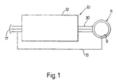
- FIGURE 1
- shows in outline an electrical drive in accordance with a first embodiment of the present invention;
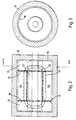
- FIGURE 2
- is a longitudinal sectional view of the motor of Figure 1;
- FIGURE 3
- is a simplified section on the line 3-3 of Figure 2;
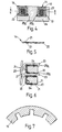
- FIGURE 4
- is a transverse section of stator windings in the motor of Figure 1;
- FIGURE 5
- shows in detail the electrical screen shown in Figure 4;
- FIGURE 6
- is a section on the line 6-6 of Figure 4;
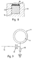
- FIGURE 7
- is a view of a detail of the end of the stator core part of the motor of Figure 1;
- FIGURE 8
- illustrates a variation of one of the screen sections of the embodiment of Figures 1 - 7;
- FIGURE 9
- illustrates an interconnection variation for the electrical drive of Figure 1;
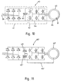
- FIGURE 10
- shows in outline an electrical drive in accordance with a second embodiment of the present invention;
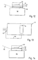
- FIGURE 11
- shows in outline an electrical drive in accordance with a third embodiment of the present invention;
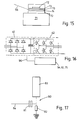
- FIGURE 12
- shows part of a high speed switching device for use in an electrical drive of the present invention;
- FIGURE 13
- shows an electronic controller incorporating the switching device of Figure 12;
- FIGURES 14 & 15
- show alternative switching devices for use in the controller of Figure 13;
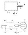
- FIGURE 16
- shows another electronic controller which may incorporate the device of Figure 12, Figure 14 or Figure 15;
- FIGURE 17
- shows an interconnection variation for the devices of Figures 12, 14 and 15;
- FIGURE 18
- shows part of an electrical drive in accordance with another embodiment of the invention; and
- FIGURE 19
- shows in outline yet another electrical drive in accordance with the present invention.
Claims (24)
- A method for the suppression of radio frequency emissions from an electrical drive (10) of the kind comprising an electronic controller (12; 40; 40'; 102) comprising high speed switching means which generates high frequency energy and an electric motor (11; 43; 43'; 101) to which power from a source of electrical power is supplied via said electronic controller, said electronic controller comprising positions which serve for the supply of electrical power to an input side of said switching means, at least one of said positions being a non-earthed position, and said method comprising providing an electrical screen (9; 9'; 14,15,16; 54, 61; 75; 101',102',103') to receive radio frequency energy which, in use, is emitted from at least a part of the electrical drive,
characterised in that said method comprises electrically connecting said electrical screen back to said non-earthed position at the input side of said switching means. - A method according to Claim 1, characterised in that use is made of an electrical screen (9; 9') which at the least, substantially wholly surrounds a part of the electric motor (11; 43; 43') from which, in use, radio frequency energy is emitted.
- An electrical drive (10) comprising an electronic controller (12; 40; 40'; 102) comprising high speed switching means which generates high frequency energy, an electrical screen (9; 9'; 14, 15, 16; 54, 61; 75; 101', 102', 103') to receive radio frequency energy which, in use, is emitted from at least a part of the electrical drive, and an electric motor (11; 43; 43'; 101) to which power from a source of electrical power is supplied via said electronic controller, said electronic controller comprising positions which serve for the supply of electrical power to an input side of said switching means and at least one of said positions being a non-earthed position, characterised in that said electrical screen (9; 9'; 14, 15, 16; 54; 61; 75; 101' 102' 103') is connected back to said non-earthed position at the input side of said switching means.
- An electrical drive according to Claim 3, characterised in that at least the electric motor (11; 43; 43'; 101) and any controller output cable (30; 103) or like interconnection means provided between the electronic controller and the electric motor is devoid of an earthed screen.
- An electrical drive according to Claim 3 or Claim 4, characterised in that the source of electrical power has a separate earth connection which is not connected to a pole of the source of electrical power to the electrical drive.
- An electrical drive according to any of Claims 3 to 5, characterised in that the electrical screen is comprised by a part of the electric motor which is not connected to earth.
- An electrical drive according to Claim 6, characterised in that the electrical screen comprises a conventional part (24; 61) of the structure of the electrical drive.
- An electrical drive according to any of Claims 3 to 7, characterised in that the electrical screen comprises a member (14, 15, 16; 27) which is additional to the structure of a conventional electrical drive.
- An electrical drive according to any of Claims 3 to 8, characterised in that, at the least, said electrical screen (9, 9') substantially wholly surrounds at least a part of the electric motor (11, 43, 43') from which, in use, radio frequency energy is emitted.
- An electrical drive according to any of Claims 3 to 9, characterised in that the electric motor incorporates a said electrical screen which is comprised by at least one of the frame, stator (24) and rotor components of the motor and arranged to receive radio frequency energy emitted by electrical windings of said motor.
- An electrical drive according to any of Claims 3 to 10, characterised in that it comprises interconnection means (103) for the transmission of power from the controller (102) to the motor (101), each of the interconnection means, controller, and motor being provided with a said screen (103', 102', 101') to receive radio frequency energy emitted by at least a part of the respective interconnection means, controller and motor and each of said screens (103', 102', 101') being connected back to a non-earthed position at the input side of the high speed switching means.
- An electrical drive according to any of Claims 3 to 11, characterised in that capacitor means (31; 45'; 81) is provided between said electrical screen and the electronic controller or said source of electrical power to said controller, said capacitor means being arranged to ensure that the electrical screen is not connected directly to the external power supply or any other electrically live point and said capacitor means having a capacitance value which presents a low impedance at the frequencies associated with radio frequency emissions and a high impedance at the frequency of the external power supply.
- An electrical drive according to any of Claims 3 to 12, characterised in that the electronic controller (40; 40') has at least two stages (41, 42) of which a first (41) does not generate high frequency energy and said electrical screen (9') is connected back to between those stages at a non-earthed position which is at the input side of the stage(s) (42) which generate(s) high frequency energy.
- An electrical drive according to any of Claims 3 to 13, characterised in that the electrical screen (14) is an electrically conductive layer (20) of a laminated construction comprising a layer of electrically conductive material having adjacent at least one surface thereof a layer of insulating material (21), said electrical screen being positioned at least in part between the motor windings (23) and associated motor structure (24).
- An electrical drive according to any of Claims 3 to 14, characterised in that the electrical screen comprises a controller screen (54; 61; 75) provided in proximity to the high speed switching means to receive radio frequency energy generated by said switching means, said controller screen being connected (56) to said non-earthed position at the input side of said switching means.
- An electrical drive according to Claim 15, characterised in that said controller screen is positioned between earth and terminals of the high speed switching means.
- An electrical drive according to Claim 15 or Claim 16, characterised in that the high speed switching means is mounted on a heat sink (52; 64; 71) and the controller screen (54; 61; 75) lies interposed between said high speed switching means and heat sink to provide a physical barrier to the direct transmission of radio frequency energy from the high speed switching means to the heat sink.
- An electrical drive according to any of Claims 15 to 17, characterised in that the controller screen substantially wholly contains the high speed switching means.
- An electric motor comprising motor windings, shield means and remaining structure, characterised in that said shield means comprises an electrical screen (9; 14) positioned between the motor windings (23) and said remaining structure (8) of the motor to receive radio frequency energy emitted by the motor windings, electrical insulation means (21) between said electrical screen and said remaining structure of the motor whereby said electrical screen is electrically insulated from said remaining structure of the motor, and a non-earthed electrically-conductive connection means (13) connected to said electrical screen, for connecting the screen to the power supply of the motor such that radio frequency current can be fed back to the power supply.
- An electric motor according to Claim 19, characterised in that the motor windings lie in a plurality of slots (19) and each of said slots has a said electrical screen associated therewith and arranged to surround the windings (23) in that slot.
- An electric motor according to Claim 20, characterised in that each said slot (19) contains at least one sleeve-like electrical screen formation (18) which surrounds the motor windings in that slot.
- An electrical motor according to Claim 21, characterised in that each sleeve-like screen formation (18) is a laminated screen which comprises a layer of electrically conductive material (20) sandwiched between two layers of insulating material (21).
- An electric motor according to Claim 20, characterised in that the base and side walls of each slot (19) serve as part of said electrical screen associated with said slot.
- An electric motor according to Claim 23, characterised in that the mouth region of a slot (19) contains a said screen (27) which is in electrical contact with respective side walls of the slot.
Applications Claiming Priority (7)
| Application Number | Priority Date | Filing Date | Title |
|---|---|---|---|
| GB9404468 | 1994-03-08 | ||
| GB9404468A GB9404468D0 (en) | 1994-03-08 | 1994-03-08 | Suppression of radio frequency emissions |
| GB9418186 | 1994-09-09 | ||
| GB9418186A GB9418186D0 (en) | 1994-03-08 | 1994-09-09 | Suppression of radio frequency emissions |
| GB9503527 | 1995-02-22 | ||
| GB9503527A GB2287363B (en) | 1994-03-08 | 1995-02-22 | Suppression of radio frequency emissions |
| PCT/GB1995/000442 WO1995024763A1 (en) | 1994-03-08 | 1995-03-02 | Suppression of radio frequency emissions |
Publications (2)
| Publication Number | Publication Date |
|---|---|
| EP0697147A1 EP0697147A1 (en) | 1996-02-21 |
| EP0697147B1 true EP0697147B1 (en) | 1998-08-12 |
Family
ID=27267085
Family Applications (1)
| Application Number | Title | Priority Date | Filing Date |
|---|---|---|---|
| EP95909887A Expired - Lifetime EP0697147B1 (en) | 1994-03-08 | 1995-03-02 | Suppression of radio frequency emissions |
Country Status (21)
| Country | Link |
|---|---|
| US (1) | US5854546A (en) |
| EP (1) | EP0697147B1 (en) |
| JP (1) | JP2898096B2 (en) |
| CN (1) | CN1040597C (en) |
| AT (1) | ATE169784T1 (en) |
| AU (1) | AU692525B2 (en) |
| BR (1) | BR9505783A (en) |
| CA (1) | CA2161255C (en) |
| CZ (1) | CZ291795A3 (en) |
| DE (2) | DE69503991T2 (en) |
| DK (1) | DK0697147T3 (en) |
| ES (1) | ES2122553T3 (en) |
| FI (1) | FI955308A0 (en) |
| GB (1) | GB2287363B (en) |
| HR (1) | HRP950111A2 (en) |
| HU (1) | HU218337B (en) |
| MX (1) | MX9504670A (en) |
| NO (1) | NO954465D0 (en) |
| PL (1) | PL178367B1 (en) |
| RU (1) | RU2155428C2 (en) |
| WO (1) | WO1995024763A1 (en) |
Families Citing this family (12)
| Publication number | Priority date | Publication date | Assignee | Title |
|---|---|---|---|---|
| US6307344B1 (en) * | 1999-03-02 | 2001-10-23 | Fasco Dc Motors, Inc. | RFI suppression package for DC electric motors |
| DE10049817B4 (en) * | 2000-10-09 | 2006-12-07 | Siemens Ag | Induction device with damping device |
| US7294400B2 (en) * | 2003-03-17 | 2007-11-13 | Hewlett-Packard Development Company, L.P. | Flexible barrier film structure |
| WO2005081608A1 (en) * | 2004-02-25 | 2005-09-01 | Zbigniew Malecki | System and method for removing streams of distorted high-frequency electromagnetic radiation |
| CN100340058C (en) * | 2005-04-01 | 2007-09-26 | 上海匣承机电科技有限公司 | Three-phase AC. electric motorelectricity-saver |
| US7723939B2 (en) * | 2006-05-23 | 2010-05-25 | Lutron Electronics Co., Inc. | Radio-frequency controlled motorized roller shade |
| JP4461120B2 (en) * | 2006-06-26 | 2010-05-12 | 日立オートモティブシステムズ株式会社 | Inverter-driven rotating machine system and electric vehicle using the same |
| US9343939B2 (en) * | 2010-12-23 | 2016-05-17 | General Electric Company | Electric motor structure to minimize electro-magnetic interference |
| CN102857035A (en) * | 2012-10-12 | 2013-01-02 | 苏州金科信汇光电科技有限公司 | High-frequency interference preventing device for servo motor |
| FR3039723B1 (en) * | 2015-07-28 | 2018-07-27 | Valeo Systemes Thermiques | ELECTRONICALLY SWITCHED ELECTRIC MOTOR AND CORRESPONDING AIR PULSE DEVICE |
| WO2019244418A1 (en) * | 2018-06-18 | 2019-12-26 | 田中 正一 | Three-phase motor drive device |
| WO2021019608A1 (en) * | 2019-07-26 | 2021-02-04 | 田中 正一 | Three-phase motor drive |
Family Cites Families (29)
| Publication number | Priority date | Publication date | Assignee | Title |
|---|---|---|---|---|
| US3397069A (en) * | 1964-12-15 | 1968-08-13 | Union Carbide Corp | Coherent self-sustaining stick of shirred and compressed tubular sausage casing |
| DE1613343B2 (en) * | 1967-10-27 | 1977-12-29 | Papst-Motoren Kg, 7742 St Georgen | SOUND-ATTACHING HOUSING FOR AN ELECTRIC MOTOR |
| US3731127A (en) * | 1971-10-19 | 1973-05-01 | Gen Electric | Generator end tooth flux shield |
| JPS5911253B2 (en) * | 1975-05-22 | 1984-03-14 | ソニー株式会社 | motor |
| JPS544314A (en) * | 1977-06-14 | 1979-01-13 | Denki Onkyo Co Ltd | Switching type stabilized dc power supply |
| JPS54126926A (en) * | 1978-03-24 | 1979-10-02 | Toshiba Electric Equip | Invertor |
| JPS6141422Y2 (en) * | 1978-05-02 | 1986-11-25 | ||
| JPS54159602A (en) * | 1978-06-07 | 1979-12-17 | Meidensha Electric Mfg Co Ltd | Manufacturing method of winding for rotary electric machine of axial air-gap type |
| CH627031A5 (en) * | 1978-08-09 | 1981-12-15 | Portescap | |
| DE3006382C2 (en) * | 1980-02-21 | 1985-10-31 | Thyssen Industrie Ag, 4300 Essen | Three-phase alternating current winding for a linear motor |
| US4329605A (en) * | 1980-10-14 | 1982-05-11 | General Motors Corporation | Electric motor having radio frequency interference radiation suppression |
| SU1075354A1 (en) * | 1982-07-08 | 1984-02-23 | Марийский Политехнический Институт Им.М.Горького | A.c.electric machine |
| US4450373A (en) * | 1983-09-12 | 1984-05-22 | General Electric Company | Apparatus for vibration reduction in dynamoelectric machines |
| JPS60106344A (en) * | 1983-11-11 | 1985-06-11 | Mabuchi Motor Co Ltd | Small-sized motor |
| US4566029A (en) * | 1984-03-23 | 1986-01-21 | Rca Corporation | Shuttered CCD camera with low noise |
| SU1249723A1 (en) * | 1984-06-22 | 1986-08-07 | Марийский Ордена Дружбы Народов Политехнический Институт Им.А.М.Горького | Shielding shell for variable magnetic field |
| US4779031A (en) * | 1985-12-30 | 1988-10-18 | Intellico, Inc. | Motor system |
| DE3642724A1 (en) * | 1986-12-13 | 1988-06-23 | Grundfos Int | ELECTRIC MOTOR WITH A FREQUENCY CONVERTER TO CONTROL THE MOTOR OPERATING SIZES |
| JPS63283447A (en) * | 1987-05-13 | 1988-11-21 | Matsushita Electric Ind Co Ltd | Radiation noise interrupting device for small dc motor |
| JP2740954B2 (en) * | 1988-11-29 | 1998-04-15 | 株式会社日立製作所 | Electric vehicle drive |
| US5006744A (en) * | 1988-12-27 | 1991-04-09 | General Electric Company | Integrated electronically commutated motor and control circuit assembly |
| US5097163A (en) * | 1989-12-22 | 1992-03-17 | Sundstrand Corporation | Electrical power generating system having reduced conducted emissions in output power |
| US5080559A (en) * | 1990-01-23 | 1992-01-14 | The United States Of America As Represented By The United States Department Of Energy | Liquid metal electric pump |
| US5026476A (en) * | 1990-06-06 | 1991-06-25 | Sumitomo Heavy Industries, Ltd. | Antivibration cover for rotary machine |
| US5515230A (en) * | 1990-09-06 | 1996-05-07 | Ashley; James R. | Poly-phase coaxial power line efficiency enhancements |
| JP2876862B2 (en) * | 1991-12-27 | 1999-03-31 | 株式会社日立製作所 | Control rod drive |
| TW299522B (en) * | 1992-05-13 | 1997-03-01 | Naito Kinshiro | |
| JP2919241B2 (en) * | 1993-09-13 | 1999-07-12 | 日本電気株式会社 | Power supply wiring |
| JP3271416B2 (en) * | 1994-02-18 | 2002-04-02 | 株式会社デンソー | POWER CONVERTER AND ELECTRIC VEHICLE DRIVE USING THE SAME |
-
1995
- 1995-02-22 GB GB9503527A patent/GB2287363B/en not_active Expired - Fee Related
- 1995-03-02 US US08/537,806 patent/US5854546A/en not_active Expired - Fee Related
- 1995-03-02 ES ES95909887T patent/ES2122553T3/en not_active Expired - Lifetime
- 1995-03-02 CN CN95190203A patent/CN1040597C/en not_active Expired - Fee Related
- 1995-03-02 WO PCT/GB1995/000442 patent/WO1995024763A1/en not_active Application Discontinuation
- 1995-03-02 AT AT95909887T patent/ATE169784T1/en not_active IP Right Cessation
- 1995-03-02 JP JP7523289A patent/JP2898096B2/en not_active Expired - Lifetime
- 1995-03-02 RU RU95122165/09A patent/RU2155428C2/en active
- 1995-03-02 DK DK95909887T patent/DK0697147T3/en active
- 1995-03-02 PL PL95311338A patent/PL178367B1/en unknown
- 1995-03-02 CZ CZ952917A patent/CZ291795A3/en unknown
- 1995-03-02 BR BR9505783A patent/BR9505783A/en not_active Application Discontinuation
- 1995-03-02 EP EP95909887A patent/EP0697147B1/en not_active Expired - Lifetime
- 1995-03-02 DE DE69503991T patent/DE69503991T2/en not_active Expired - Fee Related
- 1995-03-02 MX MX9504670A patent/MX9504670A/en not_active IP Right Cessation
- 1995-03-02 AU AU18191/95A patent/AU692525B2/en not_active Ceased
- 1995-03-02 HU HU9503197A patent/HU218337B/en not_active IP Right Cessation
- 1995-03-02 CA CA002161255A patent/CA2161255C/en not_active Expired - Fee Related
- 1995-03-02 DE DE0697147T patent/DE697147T1/en active Pending
- 1995-03-08 HR HR9503527.5A patent/HRP950111A2/en not_active Application Discontinuation
- 1995-11-06 FI FI955308A patent/FI955308A0/en unknown
- 1995-11-07 NO NO954465A patent/NO954465D0/en not_active Application Discontinuation
Also Published As
| Publication number | Publication date |
|---|---|
| DE69503991D1 (en) | 1998-09-17 |
| RU2155428C2 (en) | 2000-08-27 |
| NO954465L (en) | 1995-11-07 |
| AU1819195A (en) | 1995-09-25 |
| CZ291795A3 (en) | 1996-05-15 |
| CN1124543A (en) | 1996-06-12 |
| DE697147T1 (en) | 1996-10-24 |
| GB2287363A (en) | 1995-09-13 |
| FI955308A (en) | 1995-11-06 |
| ES2122553T3 (en) | 1998-12-16 |
| CA2161255A1 (en) | 1995-09-14 |
| PL311338A1 (en) | 1996-02-05 |
| JPH08510114A (en) | 1996-10-22 |
| FI955308A0 (en) | 1995-11-06 |
| HRP950111A2 (en) | 1997-06-30 |
| PL178367B1 (en) | 2000-04-28 |
| MX9504670A (en) | 1997-05-31 |
| AU692525B2 (en) | 1998-06-11 |
| DE69503991T2 (en) | 1999-02-18 |
| JP2898096B2 (en) | 1999-05-31 |
| NO954465D0 (en) | 1995-11-07 |
| DK0697147T3 (en) | 1999-05-17 |
| CN1040597C (en) | 1998-11-04 |
| ATE169784T1 (en) | 1998-08-15 |
| US5854546A (en) | 1998-12-29 |
| BR9505783A (en) | 1996-03-05 |
| GB9503527D0 (en) | 1995-04-12 |
| HUT73308A (en) | 1996-07-29 |
| GB2287363B (en) | 1997-12-17 |
| HU218337B (en) | 2000-07-28 |
| CA2161255C (en) | 2000-05-02 |
| HU9503197D0 (en) | 1996-01-29 |
| WO1995024763A1 (en) | 1995-09-14 |
| EP0697147A1 (en) | 1996-02-21 |
Similar Documents
| Publication | Publication Date | Title |
|---|---|---|
| Ogasawara et al. | Measurement and reduction of EMI radiated by a PWM inverter-fed AC motor drive system | |
| CA2762711C (en) | Electric motor structure to minimize electro-magnetic interference | |
| EP0697147B1 (en) | Suppression of radio frequency emissions | |
| JPH0880046A (en) | Improved type electromagnetic interference filter | |
| JP3648123B2 (en) | Inverter system grounding structure | |
| US7952251B2 (en) | Systems and methods for shielding an electric machine | |
| JP2005130575A (en) | Noise filter and motor driving device | |
| WO2021152888A1 (en) | Noise filter, noise filter device, and power conversion device | |
| JP6652691B1 (en) | Motor drive | |
| US6008560A (en) | Inverter driven motor having winding termination reducing EMI | |
| EP0150101B1 (en) | Improvements in interference suppression for semi-conducting switching devices | |
| US7342799B2 (en) | System using power converter, microsurge suppressor and microsurge suppression method | |
| JP3601118B2 (en) | Motor with stator winding | |
| JPH1118487A (en) | Grounding treatment method for conductive sheath of output cable of inverter device | |
| JP2001128467A (en) | Power conversion device | |
| US20230261470A1 (en) | Filter apparatus | |
| JP6874533B2 (en) | Electric compressor | |
| JP2000333396A (en) | Motor and variable speed drive system therefor | |
| CN110829828A (en) | Drive circuit for driving an electronically commutated motor |
Legal Events
| Date | Code | Title | Description |
|---|---|---|---|
| PUAI | Public reference made under article 153(3) epc to a published international application that has entered the european phase |
Free format text: ORIGINAL CODE: 0009012 |
|
| AK | Designated contracting states |
Kind code of ref document: A1 Designated state(s): AT BE CH DE DK ES FR GB GR IE IT LI LU MC NL PT SE |
|
| 17P | Request for examination filed |
Effective date: 19951117 |
|
| DET | De: translation of patent claims | ||
| 17Q | First examination report despatched |
Effective date: 19961219 |
|
| GRAG | Despatch of communication of intention to grant |
Free format text: ORIGINAL CODE: EPIDOS AGRA |
|
| GRAG | Despatch of communication of intention to grant |
Free format text: ORIGINAL CODE: EPIDOS AGRA |
|
| GRAH | Despatch of communication of intention to grant a patent |
Free format text: ORIGINAL CODE: EPIDOS IGRA |
|
| RAP1 | Party data changed (applicant data changed or rights of an application transferred) |
Owner name: CONTROL TECHNIQUES PLC |
|
| GRAH | Despatch of communication of intention to grant a patent |
Free format text: ORIGINAL CODE: EPIDOS IGRA |
|
| GRAA | (expected) grant |
Free format text: ORIGINAL CODE: 0009210 |
|
| AK | Designated contracting states |
Kind code of ref document: B1 Designated state(s): AT BE CH DE DK ES FR GR IE IT LI LU MC NL PT SE |
|
| REF | Corresponds to: |
Ref document number: 169784 Country of ref document: AT Date of ref document: 19980815 Kind code of ref document: T |
|
| REG | Reference to a national code |
Ref country code: CH Ref legal event code: EP |
|
| REF | Corresponds to: |
Ref document number: 69503991 Country of ref document: DE Date of ref document: 19980917 |
|
| REG | Reference to a national code |
Ref country code: IE Ref legal event code: FG4D |
|
| ET | Fr: translation filed | ||
| REG | Reference to a national code |
Ref country code: ES Ref legal event code: FG2A Ref document number: 2122553 Country of ref document: ES Kind code of ref document: T3 |
|
| REG | Reference to a national code |
Ref country code: PT Ref legal event code: SC4A Free format text: AVAILABILITY OF NATIONAL TRANSLATION Effective date: 19981022 Ref country code: CH Ref legal event code: NV Representative=s name: E. BLUM & CO. PATENTANWAELTE |
|
| REG | Reference to a national code |
Ref country code: DK Ref legal event code: T3 |
|
| PLBE | No opposition filed within time limit |
Free format text: ORIGINAL CODE: 0009261 |
|
| STAA | Information on the status of an ep patent application or granted ep patent |
Free format text: STATUS: NO OPPOSITION FILED WITHIN TIME LIMIT |
|
| 26N | No opposition filed | ||
| PGFP | Annual fee paid to national office [announced via postgrant information from national office to epo] |
Ref country code: PT Payment date: 19991216 Year of fee payment: 6 |
|
| PGFP | Annual fee paid to national office [announced via postgrant information from national office to epo] |
Ref country code: GR Payment date: 19991217 Year of fee payment: 6 |
|
| PGFP | Annual fee paid to national office [announced via postgrant information from national office to epo] |
Ref country code: MC Payment date: 19991221 Year of fee payment: 6 Ref country code: LU Payment date: 19991221 Year of fee payment: 6 |
|
| PGFP | Annual fee paid to national office [announced via postgrant information from national office to epo] |
Ref country code: DE Payment date: 19991228 Year of fee payment: 6 |
|
| PGFP | Annual fee paid to national office [announced via postgrant information from national office to epo] |
Ref country code: AT Payment date: 20000113 Year of fee payment: 6 |
|
| PGFP | Annual fee paid to national office [announced via postgrant information from national office to epo] |
Ref country code: CH Payment date: 20000211 Year of fee payment: 6 |
|
| PGFP | Annual fee paid to national office [announced via postgrant information from national office to epo] |
Ref country code: IE Payment date: 20000215 Year of fee payment: 6 |
|
| PGFP | Annual fee paid to national office [announced via postgrant information from national office to epo] |
Ref country code: BE Payment date: 20000228 Year of fee payment: 6 |
|
| PGFP | Annual fee paid to national office [announced via postgrant information from national office to epo] |
Ref country code: ES Payment date: 20000303 Year of fee payment: 6 Ref country code: DK Payment date: 20000303 Year of fee payment: 6 |
|
| PGFP | Annual fee paid to national office [announced via postgrant information from national office to epo] |
Ref country code: FR Payment date: 20000329 Year of fee payment: 6 |
|
| PGFP | Annual fee paid to national office [announced via postgrant information from national office to epo] |
Ref country code: NL Payment date: 20000331 Year of fee payment: 6 |
|
| PG25 | Lapsed in a contracting state [announced via postgrant information from national office to epo] |
Ref country code: MC Free format text: LAPSE BECAUSE OF NON-PAYMENT OF DUE FEES Effective date: 20010222 |
|
| PG25 | Lapsed in a contracting state [announced via postgrant information from national office to epo] |
Ref country code: LU Free format text: LAPSE BECAUSE OF NON-PAYMENT OF DUE FEES Effective date: 20010302 Ref country code: IE Free format text: LAPSE BECAUSE OF NON-PAYMENT OF DUE FEES Effective date: 20010302 Ref country code: DK Free format text: LAPSE BECAUSE OF NON-PAYMENT OF DUE FEES Effective date: 20010302 Ref country code: AT Free format text: LAPSE BECAUSE OF NON-PAYMENT OF DUE FEES Effective date: 20010302 |
|
| PG25 | Lapsed in a contracting state [announced via postgrant information from national office to epo] |
Ref country code: SE Free format text: LAPSE BECAUSE OF NON-PAYMENT OF DUE FEES Effective date: 20010303 Ref country code: ES Free format text: LAPSE BECAUSE OF NON-PAYMENT OF DUE FEES Effective date: 20010303 |
|
| PG25 | Lapsed in a contracting state [announced via postgrant information from national office to epo] |
Ref country code: LI Free format text: LAPSE BECAUSE OF NON-PAYMENT OF DUE FEES Effective date: 20010331 Ref country code: GR Free format text: LAPSE BECAUSE OF NON-PAYMENT OF DUE FEES Effective date: 20010331 Ref country code: CH Free format text: LAPSE BECAUSE OF NON-PAYMENT OF DUE FEES Effective date: 20010331 Ref country code: BE Free format text: LAPSE BECAUSE OF NON-PAYMENT OF DUE FEES Effective date: 20010331 |
|
| BERE | Be: lapsed |
Owner name: CONTROL TECHNIQUES P.L.C. Effective date: 20010331 |
|
| PG25 | Lapsed in a contracting state [announced via postgrant information from national office to epo] |
Ref country code: PT Free format text: LAPSE BECAUSE OF NON-PAYMENT OF DUE FEES Effective date: 20010930 |
|
| PG25 | Lapsed in a contracting state [announced via postgrant information from national office to epo] |
Ref country code: NL Free format text: LAPSE BECAUSE OF NON-PAYMENT OF DUE FEES Effective date: 20011001 |
|
| EUG | Se: european patent has lapsed |
Ref document number: 95909887.2 |
|
| REG | Reference to a national code |
Ref country code: CH Ref legal event code: PL |
|
| REG | Reference to a national code |
Ref country code: DK Ref legal event code: EBP |
|
| PG25 | Lapsed in a contracting state [announced via postgrant information from national office to epo] |
Ref country code: FR Free format text: LAPSE BECAUSE OF NON-PAYMENT OF DUE FEES Effective date: 20011130 |
|
| NLV4 | Nl: lapsed or anulled due to non-payment of the annual fee |
Effective date: 20011001 |
|
| REG | Reference to a national code |
Ref country code: FR Ref legal event code: ST |
|
| PG25 | Lapsed in a contracting state [announced via postgrant information from national office to epo] |
Ref country code: DE Free format text: LAPSE BECAUSE OF NON-PAYMENT OF DUE FEES Effective date: 20020101 |
|
| REG | Reference to a national code |
Ref country code: IE Ref legal event code: MM4A |
|
| REG | Reference to a national code |
Ref country code: PT Ref legal event code: MM4A Free format text: LAPSE DUE TO NON-PAYMENT OF FEES Effective date: 20010930 |
|
| REG | Reference to a national code |
Ref country code: ES Ref legal event code: FD2A Effective date: 20030303 |
|
| PG25 | Lapsed in a contracting state [announced via postgrant information from national office to epo] |
Ref country code: IT Free format text: LAPSE BECAUSE OF NON-PAYMENT OF DUE FEES;WARNING: LAPSES OF ITALIAN PATENTS WITH EFFECTIVE DATE BEFORE 2007 MAY HAVE OCCURRED AT ANY TIME BEFORE 2007. THE CORRECT EFFECTIVE DATE MAY BE DIFFERENT FROM THE ONE RECORDED. Effective date: 20050302 |
|
| PGFP | Annual fee paid to national office [announced via postgrant information from national office to epo] |
Ref country code: SE Payment date: 20110329 Year of fee payment: 17 |
|
| PGFP | Annual fee paid to national office [announced via postgrant information from national office to epo] |
Ref country code: IT Payment date: 20060331 Year of fee payment: 12 |