EP0696048A2 - Electron beam tubes - Google Patents
Electron beam tubes Download PDFInfo
- Publication number
- EP0696048A2 EP0696048A2 EP95305440A EP95305440A EP0696048A2 EP 0696048 A2 EP0696048 A2 EP 0696048A2 EP 95305440 A EP95305440 A EP 95305440A EP 95305440 A EP95305440 A EP 95305440A EP 0696048 A2 EP0696048 A2 EP 0696048A2
- Authority
- EP
- European Patent Office
- Prior art keywords
- tube
- cylinder
- cavities
- resonant
- drift
- Prior art date
- Legal status (The legal status is an assumption and is not a legal conclusion. Google has not performed a legal analysis and makes no representation as to the accuracy of the status listed.)
- Granted
Links
Images
Classifications
-
- H—ELECTRICITY
- H01—ELECTRIC ELEMENTS
- H01J—ELECTRIC DISCHARGE TUBES OR DISCHARGE LAMPS
- H01J23/00—Details of transit-time tubes of the types covered by group H01J25/00
- H01J23/16—Circuit elements, having distributed capacitance and inductance, structurally associated with the tube and interacting with the discharge
- H01J23/18—Resonators
-
- H—ELECTRICITY
- H01—ELECTRIC ELEMENTS
- H01J—ELECTRIC DISCHARGE TUBES OR DISCHARGE LAMPS
- H01J25/00—Transit-time tubes, e.g. klystrons, travelling-wave tubes, magnetrons
- H01J25/02—Tubes with electron stream modulated in velocity or density in a modulator zone and thereafter giving up energy in an inducing zone, the zones being associated with one or more resonators
- H01J25/10—Klystrons, i.e. tubes having two or more resonators, without reflection of the electron stream, and in which the stream is modulated mainly by velocity in the zone of the input resonator
Definitions
- This invention relates to electron beam tubes and more particularly, but not exclusively, to klystrons.
- a klystron is an amplifying device in which an electron beam is velocity modulated by a high frequency signal which is applied to an input resonant cavity, the amplified output signal being coupled from another resonant cavity.
- Figure 1 schematically shows a conventional klystron which includes an electron gun 1 for generating a beam of electrons directed along the longitudinal axis X-X.
- the high frequency signal to be amplified is coupled into the input cavity 2 via a coupling loop 3 and produces velocity modulation of electrons of the beam travelling through the cavity 2.
- the cavity 2 is followed by a drift tube 4 and, typically, several intermediate cavities, two of which 5 and 6 are illustrated, where further bunching of the electrons occurs.
- the output cavity 7 includes a coupling loop 8 via which the amplified r.f. signal is taken from the device.
- the electrons of the beam are incident on a collector 9 following the output cavity 7.
- the electron beam is focused by permanent magnets or electromagnets around the outside of the r.f. interaction structure to counteract the divergence of the beam due to space charge and prevent the beam from hitting the walls.
- the present invention arose from considering the manufacture of a low cost klystron but it is also applicable to other types of electron beam tubes employing resonant cavities.
- an electron beam tube comprising: a plurality of resonant cavities having drift spaces between them; and a gas-tight envelope comprising a unitary cylinder the inner surface of which defines the outer extent of the resonant cavities.
- the cylinder is formed as one piece without vacuum joints and not as separate sections joined together.
- This term also includes a cylinder which consists of an outer part of one material and an inner part or liner of another material.
- the cylinder is preferably of circular cross-section because of its symmetry but it could be of other cross-sectional shapes, for example, it could have an elliptical or square cross-section.
- fewer vacuum joints are required than for a conventional design. In a typical example, only two such joints are required compared to fifty or more in a conventional tube of comparable size and operating parameters. Although the joints at each end of the cylinder must be vacuum tight, joints between the cylinder and other surfaces defining the resonant cavities need only be electrically good. A tube in accordance with the invention may therefore be more easily and quickly fabricated than a conventional device. The procedure for testing vacuum integrity and making repairs is also simplified, as if a leaking seal is detected there are relatively few to inspect. Fewer components are required in a tube, reducing the number of assembly steps required in addition to reducing the number of vacuum-tight brazes which are needed.
- Another advantage is that a relatively long electron beam tube in accordance with the invention tends to be more robust than a similar conventional device.
- a conventional device would be more prone to bending, and has an increased tendency for cracks to occur, with consequent loss of vacuum integrity, during handling, transportation and installation.
- the components of the tube may be manufactured and assembled with good precision within the cylinder. This is advantageous for any electron beam tube but is particularly useful for multiple beam devices. For example, in a multiple beam klystron, a plurality of separate cathodes are distributed on the circumference of a circle and arranged to generate parallel electron beams which pass through individual drift tubes and through common cavities. Alignment is particularly critical and may be more easily obtained by using the present invention instead of a conventional construction.
- a coolant fluid which may be for example air or water
- a coolant fluid which may be for example air or water
- this surface can be made smooth, unlike a conventional klystron say, it allows uniform cooling over its surface, avoiding air pockets which could lead to localised heat spots.
- the cylinder is of copper because of its high thermal conductivity although other electrically conductive materials could be used.
- the cylinder includes two or more materials, the inner surface being electrically conductive. Providing that the inner material is sufficiently thick to allow conduction through it, this could consist of a metallisation layer on an electrically insulating outer part. Such metallisation could be provided on selected regions only of the inner surface of the cylinder, where the resonant cavities are located.
- the inner surface of the cylinder is stepped and components located within the cylinder are mounted on the steps.
- the interior configuration of the cylinder can be machined to high tolerances with modern computer controlled machining techniques.
- the accurate interior configuration in turn leads to accurate location of components within the cylinder and this is achievable with relative ease compared to the jigging required for conventional designs.
- magnetic focusing means is provided around the outside of the cylinder.
- the focusing means may be electromagnetic means or use permanent magnetic material.
- a coil may be wound around the outside of the cylinder. This is an expensive component of an electron beam tube which in conventional designs would not be salvaged from old tubes when they are scrapped.
- the electromagnetic coil means could be recovered without damaging it.
- Electromagnetic coils may be wound directly on the outer surface of the cylinder itself or kept on a separate frame about it.
- drift tubes the drift spaces between resonant cavities are enclosed by drift tubes.
- drift tubes In some designs these could be omitted but use of drift tubes ensures that resonances arising from volumes between adjacent resonant cavities do not interfere with operation of the tube.
- one or more of the resonant cavities includes a wall arranged transversely to the longitudinal axis of the cylinder and having a central aperture through which in use an electron beam is directed.
- drift tubes are used around the drift spaces, advantageously, these may be joined with two transverse walls defining respective adjacent resonant cavities. This integration reduces the number of components to be fitted in the cylinder.
- the cylinder defines the outer extent of all of the resonant cavities included within the electron beam tube.
- the end cavities say, could be separately housed but such an arrangement increases the number of vacuum joints required and reduces the advantages obtainable from use of the invention.
- At least one of the cavities is resonant at a higher frequency than the others.
- This may be a second harmonic cavity for example.
- the cavity volume may be reduced by the transverse walls being spaced a smaller distance apart than the remaining cavities but it is preferred that the outer diameter of the cavity is smaller. This enables the optimum cavity height to diameter ratio to be preserved. This may be achieved by suitably configuring the interior surface of the cylinder so that the internal diameter is reduced where the second harmonic cavity is located.
- a cylindrical wall of the required diameter is positioned inside and coaxial with the cylinder.
- an r.f. cavity structure 10 used in a klystron includes a copper cylinder 11 which forms part of the vacuum envelope and is of circular cross- section. The outer surface is smooth and its inner diameter reduces in steps from the left hand side, as shown, to the right hand side.
- a plurality of walls 12 to 19 are located inside the cylinder 11 and are arranged transversely to the longitudinal axis X-X along which an electron beam is directed during use.
- the transverse walls define resonant cavities 20, 21, 22 and 23 and have central apertures through which the electron beam is arranged to pass.
- the regions 24, 25 and 26 between the resonant cavities are drift spaces and are surrounded by drift tubes 27, 28 and 29 respectively.
- drift tube 27 forms part of a single component which also includes walls 13 and 14.
- drift tube 28 forms a component with walls 15 and 16
- drift tube 29 is combined with walls 17 and 18.
- the first and last mentioned components including drift tubes 27 and 29 respectively are identical in length and configuration except that the right hand component as shown has a smaller outer diameter to enable it to be located at the smaller internal diameter end of the cylinder 11.
- the stepped bore of the cylinder 11 facilitates assembly and ensures positional accuracy. As the inner surface of the cylinder 11 and the transverse walls can be accurately machined and matched, this ensures that concentricity is maintained.
- the resonant cavity 20 is defined by the transverse walls 12 and 13 and by the inner surface of the cylinder 11.
- the annular region 30 bound by the walls 13 and 14 and drift tube 27 does not contribute to the operation of the device and is effectively "dead" space.
- Apertures are included in the walls 13 and 14 to enable the region 30 to be evacuated once the structure is assembled and similarly the other transverse walls also include such apertures.
- the joints made between the walls 13 to 18 and the inner surface of the cylinder 11 are not required to be vacuum tight, these only being required at locations 31 and 32 at the ends of the cylinder 11.
- Figure 3 illustrates the structure of Figure 2 included in a klystron having an electron gun assembly 33 arranged at the left hand end as shown and a collector 34 with coupling loops 35 and 36.
- a frame 37 carries electromagnetic coils 38 for focusing and air is directed over the outer surface of the cylinder 11 via duct 39.
- the cylinder 11 comprises an outer region of one material and an inner lining of another material.
- the cylinder may have an outer tube of ceramic material and an inner metallisation layer sufficiently thick for good current conduction.
- a resonant cavity structure for use in a tube in accordance with the invention is similar to that shown in Figure 2 but includes a second harmonic resonant cavity 40 in place of one of the larger cavities.
- the outer surface of the cavity 40 is defined by a cylindrical wall 41 located on annular flanges 42 and 43 on the transverse wall 16 and 17.
Abstract
Description
- This invention relates to electron beam tubes and more particularly, but not exclusively, to klystrons.
- A klystron is an amplifying device in which an electron beam is velocity modulated by a high frequency signal which is applied to an input resonant cavity, the amplified output signal being coupled from another resonant cavity. Figure 1 schematically shows a conventional klystron which includes an electron gun 1 for generating a beam of electrons directed along the longitudinal axis X-X. The high frequency signal to be amplified is coupled into the input cavity 2 via a coupling loop 3 and produces velocity modulation of electrons of the beam travelling through the cavity 2. The cavity 2 is followed by a drift tube 4 and, typically, several intermediate cavities, two of which 5 and 6 are illustrated, where further bunching of the electrons occurs. The
output cavity 7 includes a coupling loop 8 via which the amplified r.f. signal is taken from the device. The electrons of the beam are incident on a collector 9 following theoutput cavity 7. The electron beam is focused by permanent magnets or electromagnets around the outside of the r.f. interaction structure to counteract the divergence of the beam due to space charge and prevent the beam from hitting the walls. - The present invention arose from considering the manufacture of a low cost klystron but it is also applicable to other types of electron beam tubes employing resonant cavities.
- According to the invention, there is provided an electron beam tube comprising: a plurality of resonant cavities having drift spaces between them; and a gas-tight envelope comprising a unitary cylinder the inner surface of which defines the outer extent of the resonant cavities.
- By the term "unitary" it is meant that the cylinder is formed as one piece without vacuum joints and not as separate sections joined together. This term also includes a cylinder which consists of an outer part of one material and an inner part or liner of another material. The cylinder is preferably of circular cross-section because of its symmetry but it could be of other cross-sectional shapes, for example, it could have an elliptical or square cross-section.
- As the envelope defines part of the plurality of resonant cavities fewer vacuum joints are required than for a conventional design. In a typical example, only two such joints are required compared to fifty or more in a conventional tube of comparable size and operating parameters. Although the joints at each end of the cylinder must be vacuum tight, joints between the cylinder and other surfaces defining the resonant cavities need only be electrically good. A tube in accordance with the invention may therefore be more easily and quickly fabricated than a conventional device. The procedure for testing vacuum integrity and making repairs is also simplified, as if a leaking seal is detected there are relatively few to inspect. Fewer components are required in a tube, reducing the number of assembly steps required in addition to reducing the number of vacuum-tight brazes which are needed.
- Another advantage is that a relatively long electron beam tube in accordance with the invention tends to be more robust than a similar conventional device. A conventional device would be more prone to bending, and has an increased tendency for cracks to occur, with consequent loss of vacuum integrity, during handling, transportation and installation.
- The components of the tube may be manufactured and assembled with good precision within the cylinder. This is advantageous for any electron beam tube but is particularly useful for multiple beam devices. For example, in a multiple beam klystron, a plurality of separate cathodes are distributed on the circumference of a circle and arranged to generate parallel electron beams which pass through individual drift tubes and through common cavities. Alignment is particularly critical and may be more easily obtained by using the present invention instead of a conventional construction.
- Preferably means are provided for flowing a coolant fluid, which may be for example air or water, over the outer surface of the cylinder. As this surface can be made smooth, unlike a conventional klystron say, it allows uniform cooling over its surface, avoiding air pockets which could lead to localised heat spots.
- It may be preferred embodiment of the invention, the cylinder is of copper because of its high thermal conductivity although other electrically conductive materials could be used. In one embodiment, the cylinder includes two or more materials, the inner surface being electrically conductive. Providing that the inner material is sufficiently thick to allow conduction through it, this could consist of a metallisation layer on an electrically insulating outer part. Such metallisation could be provided on selected regions only of the inner surface of the cylinder, where the resonant cavities are located.
- Advantageously, the inner surface of the cylinder is stepped and components located within the cylinder are mounted on the steps. The interior configuration of the cylinder can be machined to high tolerances with modern computer controlled machining techniques. The accurate interior configuration in turn leads to accurate location of components within the cylinder and this is achievable with relative ease compared to the jigging required for conventional designs.
- Advantageously, magnetic focusing means is provided around the outside of the cylinder. The focusing means may be electromagnetic means or use permanent magnetic material. For example, a coil may be wound around the outside of the cylinder. This is an expensive component of an electron beam tube which in conventional designs would not be salvaged from old tubes when they are scrapped. However, in a tube in accordance with the invention, the electromagnetic coil means could be recovered without damaging it. Electromagnetic coils may be wound directly on the outer surface of the cylinder itself or kept on a separate frame about it.
- Advantageously, the drift spaces between resonant cavities are enclosed by drift tubes. In some designs these could be omitted but use of drift tubes ensures that resonances arising from volumes between adjacent resonant cavities do not interfere with operation of the tube.
- Preferably, one or more of the resonant cavities includes a wall arranged transversely to the longitudinal axis of the cylinder and having a central aperture through which in use an electron beam is directed. Where drift tubes are used around the drift spaces, advantageously, these may be joined with two transverse walls defining respective adjacent resonant cavities. This integration reduces the number of components to be fitted in the cylinder.
- It may be preferred that the cylinder defines the outer extent of all of the resonant cavities included within the electron beam tube. However, the end cavities, say, could be separately housed but such an arrangement increases the number of vacuum joints required and reduces the advantages obtainable from use of the invention.
- In another advantageous arrangement, at least one of the cavities is resonant at a higher frequency than the others. This may be a second harmonic cavity for example. The cavity volume may be reduced by the transverse walls being spaced a smaller distance apart than the remaining cavities but it is preferred that the outer diameter of the cavity is smaller. This enables the optimum cavity height to diameter ratio to be preserved. This may be achieved by suitably configuring the interior surface of the cylinder so that the internal diameter is reduced where the second harmonic cavity is located. In an alternative embodiment, a cylindrical wall of the required diameter is positioned inside and coaxial with the cylinder.
- Some ways in which the invention may be performed is now described by way of example with reference to the accompanying drawings in which:
- Figure 2 schematically illustrates a resonant cavity structure;
- Figure 3 schematically shows a klystron in accordance with the invention using the structure of Figure 2; and
- Figure 4 schematically illustrates another resonant cavity structure.
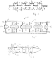
- With reference to Figure 2, an r.f.
cavity structure 10 used in a klystron includes acopper cylinder 11 which forms part of the vacuum envelope and is of circular cross- section. The outer surface is smooth and its inner diameter reduces in steps from the left hand side, as shown, to the right hand side. A plurality of walls 12 to 19 are located inside thecylinder 11 and are arranged transversely to the longitudinal axis X-X along which an electron beam is directed during use. The transverse walls defineresonant cavities regions drift tubes - The three
drift tubes tube 27 forms part of a single component which also includeswalls tube 28 forms a component withwalls 15 and 16, and drifttube 29 is combined withwalls 17 and 18. The first and last mentioned components includingdrift tubes cylinder 11. - The stepped bore of the
cylinder 11 facilitates assembly and ensures positional accuracy. As the inner surface of thecylinder 11 and the transverse walls can be accurately machined and matched, this ensures that concentricity is maintained. - The
resonant cavity 20 is defined by thetransverse walls 12 and 13 and by the inner surface of thecylinder 11. Theannular region 30 bound by thewalls tube 27 does not contribute to the operation of the device and is effectively "dead" space. Apertures (not shown) are included in thewalls region 30 to be evacuated once the structure is assembled and similarly the other transverse walls also include such apertures. - The joints made between the
walls 13 to 18 and the inner surface of thecylinder 11 are not required to be vacuum tight, these only being required atlocations cylinder 11. - Figure 3 illustrates the structure of Figure 2 included in a klystron having an
electron gun assembly 33 arranged at the left hand end as shown and acollector 34 withcoupling loops frame 37 carrieselectromagnetic coils 38 for focusing and air is directed over the outer surface of thecylinder 11 viaduct 39. - In another embodiment of the invention, the
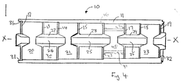
cylinder 11 comprises an outer region of one material and an inner lining of another material. For example, the cylinder may have an outer tube of ceramic material and an inner metallisation layer sufficiently thick for good current conduction. - With reference to Figure 4, a resonant cavity structure for use in a tube in accordance with the invention is similar to that shown in Figure 2 but includes a second harmonic resonant cavity 40 in place of one of the larger cavities. The outer surface of the cavity 40 is defined by a cylindrical wall 41 located on
annular flanges transverse wall 16 and 17.
Claims (15)
- An electron beam tube comprising: a plurality of resonant cavities (20 to 23) having drift spaces (24 to 26) between them; and a gas-tight envelope comprising a unitary cylinder (11) the inner surface of which defines the outer extent of the resonant cavities (20 to 23).
- A tube as claimed in claim 1 and including a drift tube (27 to 29) between adjacent cavities (20 to 23).
- A tube as claimed in claim 2 and wherein the drift tube (27, 28, 29) is joined to two transverse walls (13 to 18) partly defining respective adjacent resonant cavities (20 to 23).
- A tube as claimed in claim 1, 2 or 3 and wherein all of the resonant cavities (20 to 23) included in the tube are partly defined by the unitary cylinder (11).
- A tube as claimed in claim 1, 2 or 3 and including at least one resonant cavity (40) having an outer extent which is defined by a cylindrical wall (41) located inside and spaced from the cylinder (11).
- A tube as claimed in any preceding claim and including a resonant cavity (40) of higher frequency than other cavities included in the tube.
- A tube as claimed in claim 6 wherein the resonant cavity of higher frequency (40) is a second harmonic cavity.
- A tube as claimed in any preceding claim wherein the cylinder (11) has an inner surface which is stepped.
- A tube as claimed in any preceding claim wherein the cylinder (11) is wholly of metal.
- A tube as claimed in any preceding claim wherein the resonant cavities (12 to 19) are further defined by plates arranged normal to the longitudinal axis of the cylinder.
- A tube as claimed in any preceding claim and including means (39) for flowing a coolant fluid over the outer surface of the cylinder.
- A tube as claimed in any preceding claim and including electromagnetic coil means (38) around the outside of the cylinder.
- A tube as claimed in claim 12 wherein the coil means (38) is wound on a frame (37) located outside the cylinder (11).
- A tube as claimed in any one of claims 1 to 11 and including permanent magnetic focusing means around the outside of the cylinder.
- A klystron in accordance with any preceding claim.
Applications Claiming Priority (2)
| Application Number | Priority Date | Filing Date | Title |
|---|---|---|---|
| GB9415713A GB2292001B (en) | 1994-08-03 | 1994-08-03 | Electron beam tubes |
| GB9415713 | 1994-08-03 |
Publications (3)
| Publication Number | Publication Date |
|---|---|
| EP0696048A2 true EP0696048A2 (en) | 1996-02-07 |
| EP0696048A3 EP0696048A3 (en) | 1998-03-18 |
| EP0696048B1 EP0696048B1 (en) | 2002-10-09 |
Family
ID=10759364
Family Applications (1)
| Application Number | Title | Priority Date | Filing Date |
|---|---|---|---|
| EP95305440A Expired - Lifetime EP0696048B1 (en) | 1994-08-03 | 1995-08-03 | Electron beam tubes |
Country Status (6)
| Country | Link |
|---|---|
| US (1) | US5821693A (en) |
| EP (1) | EP0696048B1 (en) |
| JP (1) | JP3900377B2 (en) |
| CA (1) | CA2155251C (en) |
| DE (1) | DE69528500T2 (en) |
| GB (1) | GB2292001B (en) |
Families Citing this family (5)
| Publication number | Priority date | Publication date | Assignee | Title |
|---|---|---|---|---|
| GB9724960D0 (en) * | 1997-11-27 | 1998-01-28 | Eev Ltd | Electron beam tubes |
| US6885152B2 (en) * | 2003-03-28 | 2005-04-26 | Motorola, Inc. | Multilayer field emission klystron |
| CN107393789A (en) * | 2017-09-01 | 2017-11-24 | 广东工业大学 | A kind of coaxial TM10,1,0 mode coupling chamber chains |
| CN109256309B (en) * | 2018-08-28 | 2021-03-26 | 电子科技大学 | S-band miniaturized metamaterial extension interaction oscillator |
| CN111785598B (en) * | 2020-07-23 | 2023-08-08 | 中国舰船研究设计中心 | Distributed output resonant cavity with gradually changed gap width |
Family Cites Families (23)
| Publication number | Priority date | Publication date | Assignee | Title |
|---|---|---|---|---|
| GB582165A (en) * | 1940-10-16 | 1946-11-07 | Standard Telephones Cables Ltd | Improvements in means for adjusting high frequency electric discharge devices |
| US2859374A (en) * | 1952-12-18 | 1958-11-04 | Hughes Aircraft Co | Microwave tube |
| US3116435A (en) * | 1959-07-28 | 1963-12-31 | Eitel Mccullough Inc | Velocity modulation tube |
| DE1491509B1 (en) * | 1961-10-30 | 1971-08-26 | Varian Associates | ELECTRON BEAM GENERATORS FOR HIGH PERFORMANCE TUBE |
| US3231779A (en) * | 1962-06-25 | 1966-01-25 | Gen Electric | Elastic wave responsive apparatus |
| GB1054461A (en) * | 1963-02-06 | |||
| GB1067355A (en) * | 1964-11-26 | 1967-05-03 | Varian Associates | High frequency electron beam tube |
| US3502934A (en) * | 1967-09-15 | 1970-03-24 | Varian Associates | High frequency electron discharge devices having improved mode suppression means for cavities with re-entrant drift tubes |
| GB1289179A (en) * | 1969-09-24 | 1972-09-13 | ||
| FR2153585A5 (en) * | 1971-09-16 | 1973-05-04 | Thomson Csf | |
| FR2234651B1 (en) * | 1973-06-19 | 1976-11-12 | Thomson Csf | |
| FR2270758B1 (en) * | 1974-05-10 | 1978-07-13 | Cgr Mev | |
| IT1143751B (en) * | 1977-08-01 | 1986-10-22 | Sits Soc It Telecom Siemens | KLYSTRON ADJUSTABLE OSCILLATOR |
| IT1202869B (en) * | 1979-01-24 | 1989-02-15 | Sits Soc It Telecom Siemens | KLYSTRON TWO CAVITY OSCILLATOR |
| US4661784A (en) * | 1979-06-27 | 1987-04-28 | Raytheon Company | Klystron having fixed and variable tuning mechanisms |
| JPS5925148A (en) * | 1982-08-02 | 1984-02-09 | Nec Corp | Multi-cavity klystron of large power |
| GB2164488B (en) * | 1984-09-18 | 1988-05-11 | English Electric Valve Co Ltd | Improvements in or relating to coupled cavity travelling wave tubes |
| US4800322A (en) * | 1984-10-23 | 1989-01-24 | Litton Systems, Inc. | Broadband klystron cavity arrangement |
| US4611149A (en) * | 1984-11-07 | 1986-09-09 | Varian Associates, Inc. | Beam tube with density plus velocity modulation |
| FR2599554A1 (en) * | 1986-05-30 | 1987-12-04 | Thomson Csf | MULTI-BEAM KLYSTRON OPERATING AT MODE TM02 |
| GB9310832D0 (en) * | 1993-05-26 | 1993-07-14 | Eev Ltd | Electron beam tubes |
| US5469022A (en) * | 1993-07-30 | 1995-11-21 | Litton Systems, Inc. | Extended interaction output circuit using modified disk-loaded waveguide |
| JP2551352B2 (en) * | 1993-10-06 | 1996-11-06 | 日本電気株式会社 | Multi-cavity klystron |
-
1994
- 1994-08-03 GB GB9415713A patent/GB2292001B/en not_active Expired - Fee Related
-
1995
- 1995-08-02 CA CA002155251A patent/CA2155251C/en not_active Expired - Fee Related
- 1995-08-03 EP EP95305440A patent/EP0696048B1/en not_active Expired - Lifetime
- 1995-08-03 DE DE69528500T patent/DE69528500T2/en not_active Expired - Lifetime
- 1995-08-03 US US08/510,739 patent/US5821693A/en not_active Expired - Lifetime
- 1995-08-03 JP JP19842995A patent/JP3900377B2/en not_active Expired - Lifetime
Non-Patent Citations (1)
| Title |
|---|
| None |
Also Published As
| Publication number | Publication date |
|---|---|
| JP3900377B2 (en) | 2007-04-04 |
| CA2155251C (en) | 2006-10-10 |
| GB2292001A (en) | 1996-02-07 |
| GB9415713D0 (en) | 1994-09-21 |
| EP0696048B1 (en) | 2002-10-09 |
| CA2155251A1 (en) | 1996-02-04 |
| EP0696048A3 (en) | 1998-03-18 |
| JPH0864143A (en) | 1996-03-08 |
| US5821693A (en) | 1998-10-13 |
| DE69528500T2 (en) | 2003-04-17 |
| DE69528500D1 (en) | 2002-11-14 |
| GB2292001B (en) | 1998-04-22 |
Similar Documents
| Publication | Publication Date | Title |
|---|---|---|
| US3169206A (en) | High frequency tube method and apparatus | |
| EP0696048B1 (en) | Electron beam tubes | |
| GB2326274A (en) | Electron gun for multibeam electron tube | |
| US6025678A (en) | Linear-beam microwave tube with output cavity beyond the collector | |
| CA1044805A (en) | Permanent magnet structure for cross-field tubes | |
| US5332948A (en) | X-z geometry periodic permanent magnet focusing system | |
| US5239235A (en) | Multiple-beam microwave tube with coaxial output and coaxial collector | |
| US3324337A (en) | High frequency electron discharge device and focusing means therefor | |
| US3240983A (en) | High frequency apparatus | |
| US5736820A (en) | Cavity arrangements | |
| JP2020087705A (en) | Microwave tube and manufacturing method thereof | |
| US3886384A (en) | Collector electrode | |
| JP2602297B2 (en) | Gyrotron | |
| JPH0330991Y2 (en) | ||
| GB2602129A (en) | Electron gun | |
| JP2677212B2 (en) | Method of manufacturing straight beam microwave tube | |
| JPH0227485Y2 (en) | ||
| JPH0112773Y2 (en) | ||
| JPH0327326Y2 (en) | ||
| GB2278495A (en) | Electron beam tubes | |
| JP2597386B2 (en) | Gyrotron | |
| US3358181A (en) | Microwave tube apparatus having a solid block body with drift tube cooling means | |
| JP2808938B2 (en) | High power microwave tube | |
| JPH04368753A (en) | Gyrotron tube | |
| IL106249A (en) | X-Z geometry periodic permanent magnet focusing system |
Legal Events
| Date | Code | Title | Description |
|---|---|---|---|
| PUAI | Public reference made under article 153(3) epc to a published international application that has entered the european phase |
Free format text: ORIGINAL CODE: 0009012 |
|
| AK | Designated contracting states |
Kind code of ref document: A2 Designated state(s): CH DE FR IT LI Kind code of ref document: A2 Designated state(s): CH DE FR GB IT LI |
|
| PUAL | Search report despatched |
Free format text: ORIGINAL CODE: 0009013 |
|
| AK | Designated contracting states |
Kind code of ref document: A3 Designated state(s): CH DE FR GB IT LI |
|
| 17P | Request for examination filed |
Effective date: 19980914 |
|
| 17Q | First examination report despatched |
Effective date: 19981123 |
|
| GRAG | Despatch of communication of intention to grant |
Free format text: ORIGINAL CODE: EPIDOS AGRA |
|
| GRAG | Despatch of communication of intention to grant |
Free format text: ORIGINAL CODE: EPIDOS AGRA |
|
| GRAH | Despatch of communication of intention to grant a patent |
Free format text: ORIGINAL CODE: EPIDOS IGRA |
|
| RAP1 | Party data changed (applicant data changed or rights of an application transferred) |
Owner name: MARCONI APPLIED TECHNOLOGIES LIMITED |
|
| GRAH | Despatch of communication of intention to grant a patent |
Free format text: ORIGINAL CODE: EPIDOS IGRA |
|
| GRAA | (expected) grant |
Free format text: ORIGINAL CODE: 0009210 |
|
| AK | Designated contracting states |
Kind code of ref document: B1 Designated state(s): CH DE FR IT LI |
|
| RBV | Designated contracting states (corrected) |
Designated state(s): CH DE FR IT LI |
|
| REG | Reference to a national code |
Ref country code: CH Ref legal event code: EP |
|
| RAP2 | Party data changed (patent owner data changed or rights of a patent transferred) |
Owner name: E2V TECHNOLOGIES LIMITED |
|
| REF | Corresponds to: |
Ref document number: 69528500 Country of ref document: DE Date of ref document: 20021114 |
|
| REG | Reference to a national code |
Ref country code: CH Ref legal event code: NV Representative=s name: BOVARD AG PATENTANWAELTE |
|
| ET | Fr: translation filed | ||
| PLBE | No opposition filed within time limit |
Free format text: ORIGINAL CODE: 0009261 |
|
| STAA | Information on the status of an ep patent application or granted ep patent |
Free format text: STATUS: NO OPPOSITION FILED WITHIN TIME LIMIT |
|
| 26N | No opposition filed |
Effective date: 20030710 |
|
| REG | Reference to a national code |
Ref country code: CH Ref legal event code: PFA Owner name: E2V TECHNOLOGIES (UK) LIMITED Free format text: E2V TECHNOLOGIES LIMITED#106, WATERHOUSE LANE#CHELMSFORD, ESSEX CM1 2QU (GB) -TRANSFER TO- E2V TECHNOLOGIES (UK) LIMITED#106 WATERHOUSE LANE#CHELMSFORD, ESSEX CM1 2QU (GB) |
|
| REG | Reference to a national code |
Ref country code: FR Ref legal event code: CD Ref country code: FR Ref legal event code: CA |
|
| PGFP | Annual fee paid to national office [announced via postgrant information from national office to epo] |
Ref country code: CH Payment date: 20100812 Year of fee payment: 16 |
|
| PGFP | Annual fee paid to national office [announced via postgrant information from national office to epo] |
Ref country code: IT Payment date: 20100814 Year of fee payment: 16 Ref country code: DE Payment date: 20100728 Year of fee payment: 16 |
|
| REG | Reference to a national code |
Ref country code: CH Ref legal event code: PFA Owner name: E2V TECHNOLOGIES (UK) LIMITED Free format text: E2V TECHNOLOGIES (UK) LIMITED#106 WATERHOUSE LANE#CHELMSFORD, ESSEX CM1 2QU (GB) -TRANSFER TO- E2V TECHNOLOGIES (UK) LIMITED#106 WATERHOUSE LANE#CHELMSFORD, ESSEX CM1 2QU (GB) |
|
| REG | Reference to a national code |
Ref country code: CH Ref legal event code: PL |
|
| PG25 | Lapsed in a contracting state [announced via postgrant information from national office to epo] |
Ref country code: LI Free format text: LAPSE BECAUSE OF NON-PAYMENT OF DUE FEES Effective date: 20110831 Ref country code: CH Free format text: LAPSE BECAUSE OF NON-PAYMENT OF DUE FEES Effective date: 20110831 |
|
| PG25 | Lapsed in a contracting state [announced via postgrant information from national office to epo] |
Ref country code: IT Free format text: LAPSE BECAUSE OF NON-PAYMENT OF DUE FEES Effective date: 20110803 |
|
| REG | Reference to a national code |
Ref country code: DE Ref legal event code: R119 Ref document number: 69528500 Country of ref document: DE Effective date: 20120301 |
|
| PG25 | Lapsed in a contracting state [announced via postgrant information from national office to epo] |
Ref country code: DE Free format text: LAPSE BECAUSE OF NON-PAYMENT OF DUE FEES Effective date: 20120301 |
|
| PGFP | Annual fee paid to national office [announced via postgrant information from national office to epo] |
Ref country code: FR Payment date: 20130808 Year of fee payment: 19 |
|
| REG | Reference to a national code |
Ref country code: FR Ref legal event code: ST Effective date: 20150430 |
|
| PG25 | Lapsed in a contracting state [announced via postgrant information from national office to epo] |
Ref country code: FR Free format text: LAPSE BECAUSE OF NON-PAYMENT OF DUE FEES Effective date: 20140901 |