EP0696005B1 - Onboard-Messsystem - Google Patents
Onboard-Messsystem Download PDFInfo
- Publication number
- EP0696005B1 EP0696005B1 EP95302812A EP95302812A EP0696005B1 EP 0696005 B1 EP0696005 B1 EP 0696005B1 EP 95302812 A EP95302812 A EP 95302812A EP 95302812 A EP95302812 A EP 95302812A EP 0696005 B1 EP0696005 B1 EP 0696005B1
- Authority
- EP
- European Patent Office
- Prior art keywords
- measurement
- modules
- control
- module
- control module
- Prior art date
- Legal status (The legal status is an assumption and is not a legal conclusion. Google has not performed a legal analysis and makes no representation as to the accuracy of the status listed.)
- Expired - Lifetime
Links
- 238000005259 measurement Methods 0.000 title claims description 84
- 239000000835 fiber Substances 0.000 claims description 27
- 238000000034 method Methods 0.000 claims description 26
- 238000012360 testing method Methods 0.000 claims description 10
- 230000007613 environmental effect Effects 0.000 claims description 9
- 238000004891 communication Methods 0.000 claims description 8
- 238000003860 storage Methods 0.000 claims description 8
- 239000000463 material Substances 0.000 claims description 6
- 230000003287 optical effect Effects 0.000 claims description 6
- 238000007789 sealing Methods 0.000 claims 1
- 239000000047 product Substances 0.000 description 17
- 238000004519 manufacturing process Methods 0.000 description 8
- 238000010586 diagram Methods 0.000 description 4
- 238000010276 construction Methods 0.000 description 3
- 230000005855 radiation Effects 0.000 description 3
- 239000000919 ceramic Substances 0.000 description 2
- 238000010168 coupling process Methods 0.000 description 2
- 238000005859 coupling reaction Methods 0.000 description 2
- 239000002184 metal Substances 0.000 description 2
- 238000012986 modification Methods 0.000 description 2
- 230000004048 modification Effects 0.000 description 2
- 230000000737 periodic effect Effects 0.000 description 2
- 239000004033 plastic Substances 0.000 description 2
- 239000000126 substance Substances 0.000 description 2
- 241000270728 Alligator Species 0.000 description 1
- 239000002253 acid Substances 0.000 description 1
- 239000000853 adhesive Substances 0.000 description 1
- 230000001070 adhesive effect Effects 0.000 description 1
- 239000007795 chemical reaction product Substances 0.000 description 1
- 239000004020 conductor Substances 0.000 description 1
- 238000011109 contamination Methods 0.000 description 1
- 230000008878 coupling Effects 0.000 description 1
- 230000001066 destructive effect Effects 0.000 description 1
- 210000005069 ears Anatomy 0.000 description 1
- 239000013536 elastomeric material Substances 0.000 description 1
- 239000013305 flexible fiber Substances 0.000 description 1
- 239000011521 glass Substances 0.000 description 1
- 230000001788 irregular Effects 0.000 description 1
- 238000005304 joining Methods 0.000 description 1
- 230000003137 locomotive effect Effects 0.000 description 1
- 238000012423 maintenance Methods 0.000 description 1
- 239000013307 optical fiber Substances 0.000 description 1
- 238000012545 processing Methods 0.000 description 1
- 239000003507 refrigerant Substances 0.000 description 1
- 230000001172 regenerating effect Effects 0.000 description 1
- 238000005476 soldering Methods 0.000 description 1
- 238000005406 washing Methods 0.000 description 1
Images


Classifications
-
- G—PHYSICS
- G01—MEASURING; TESTING
- G01D—MEASURING NOT SPECIALLY ADAPTED FOR A SPECIFIC VARIABLE; ARRANGEMENTS FOR MEASURING TWO OR MORE VARIABLES NOT COVERED IN A SINGLE OTHER SUBCLASS; TARIFF METERING APPARATUS; MEASURING OR TESTING NOT OTHERWISE PROVIDED FOR
- G01D9/00—Recording measured values
- G01D9/005—Solid-state data loggers
-
- H—ELECTRICITY
- H04—ELECTRIC COMMUNICATION TECHNIQUE
- H04Q—SELECTING
- H04Q9/00—Arrangements in telecontrol or telemetry systems for selectively calling a substation from a main station, in which substation desired apparatus is selected for applying a control signal thereto or for obtaining measured values therefrom
Definitions
- the present invention relates to a measuring method and apparatus for providing a record of environmental factors to which a product is exposed during a manufacturing process or the like and particularly to such a method and apparatus for generating substantially continuous data.
- Manufacturing processes are designed to operate in a predetermined manner wherein environmental factors, especially those which may be critical to the process, are controlled within acceptable tolerances. Depending upon the process, it may be desirable to control pressure, radiation, vibration, temperature, humidity, pH or other parameters to which a product is exposed. Although it is possible to monitor these factors with instruments positioned at various stages in the process, the actual parameters to which a manufactured product is subjected at other stages may be relatively unknown because of harsh environmental conditions or inconvenience of probing those areas. For example, some manufacturing processes involve extremes in temperature, acidity, alkalinity, and the like where the interposition of test leads is difficult or impractical. In any case, it is not generally feasible to explore multiple parameters at every stage along a manufacturing process even in the absence of extremes. Rather, the data is discontinuous, containing gaps, wherein data, if it were available, might have revealed unacceptable conditions potentially resulting in a flawed or even dangerous end product.
- DE 4 230 358 A describes a method for collecting data in household devices such as washing machines or refrigerators, the devices comprising a microcomputer storing data from sensors measuring physical data relating to the device.
- US-A-5 065 321 discloses an event recorder for vehicles, particularly locomotives.
- a recording device receives sensor data and transmits this via an RF link.
- a laptop computer can be connected to the event recorder to receive data, and then taken to a wayside station for downloading the data.
- an on-board measurement system comprising a control module and a plurality of measurement modules is attached to a movable unit or product for logging data concerning environmental factors on a substantially continuous basis.
- Separate modules are adapted to measure separate parameters such as temperature, humidity, radiation, vibration, voltage or the like and are suitably positioned in line for communication with a common control module having microprocessor means for programming a measurement sequence and including memory means for collecting data from the measurement modules.
- the modules are sealingly enclosed, being formed of an environment impervious material, and are suitably coupled together via optical links.
- An additional optical transceiver is utilized for coupling an external command computer to the control module for initially programming the system, e.g. for taking specified measurements at given time intervals, and for receiving stored data for analysis and display.
- Information from the control module can be downloaded while the control module is still attached to the product. Alternatively, the control module can be removed from the measurement modules and replaced, after which the removed control module is read out.
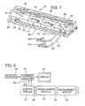
- such apparatus includes a control module 12 and plural measurement modules 14, 16 and 18 disposed in an in-line configuration.
- the modules are desirably formed of environment impervious material which suitably comprises glass or ceramic, or a plastic capable of withstanding high temperatures. Alternatively, in some environments a metal construction is suitable, but obviously the material depends upon the particular circumstances with the end in view being a rugged construction capable of withstanding harsh conditions.
- Each of the modules is provided with a lower, flat base portion 20 adapting the same for attachment to a unit or product via fastener holes 22 disposed proximate lateral edges of the base portion.
- Base portion 20 for measurement modules 14, 16 and 18 is secured through the underside thereof by fastener means (not shown) to the module sections 24, 26 and 28 thereabove, but control module upper section 30 is suitably provided with side ears 32 receiving fasteners 34 adapted for holding upper portion 30 to lower base portion 20'.
- fasteners 34 By disengagement of fasteners 34, control module 12 is easily disengaged and removed from the product being manufactured or processed, as well as from the adjoining measurement module 14.
- control module 12 is used for directing operation of measurement modules 14 and 16 by way of intermodule bus connections 36 and 38 which may include conventional plug and socket arrangements for communicating digital data and control signals between the modules.
- control module 12 is selectably connected to an external command computer 40 via control and data bus 42 for the purpose of initially programming the control module as well as receiving data therefrom.
- Command computer 40 is supplied with a display unit 44, suitably of the cathode ray tube or LCD variety, and a manually operated keyboard 46. While connections 36, 38 and 42 are suitably buses with conventional plug and socket means for interconnecting modules, optical means as hereinafter more fully described are preferred in order to render the measurement system comprising elements 12, 14 and 16 more impervious to the immediate environment.
- Command computer 40 and means 44 and 46 are not physically part of the measurement apparatus attached to the product under test, but rather the command computer is connected to control module 12 only periodically for programming the logging apparatus, and receiving data therefrom.
- keyboard 46 may be employed in conjunction with computer 40 and display unit 44 for designing a testing regime and developing a measuring program which is then downloaded to control module 12.
- the command computer is disconnected and subsequently, after the on-board measuring apparatus comprising modules 12, 14 and 16 has passed through an entire process sequence, command computer 40 is re-connected to module 12 for receiving measurement data stored therein.
- the measurement data is suitably portrayed on display means 44.
- an on-board measurement apparatus 10 is illustrated as fastened to the side of one of a series of small refrigerators 48 passing along a conveyor 50.
- Apparatus 10 includes a control module 12 and a plurality measurement modules disposed in-line therewith.
- One of the measurement modules is provided with a test lead or cable 52 which is connected, by means not shown, to a voltage within the refrigerator, or alternatively, to a refrigerant temperature measuring sensor.
- Other of the measurement modules are suitably employed to measure ambient temperature, vibration, or the like.
- the refrigerator is suitably supplied on the side or the back thereof with threaded sockets for receiving fasteners securing a measurement apparatus 10 to the side or back of the refrigerator.
- the base 20 may be magnetized for temporary attachment to the refrigerator.
- the apparatus 10 or module 12 is disengaged from refrigerator 48 and re-connected to the command computer for read out of the data gathered in control module 12, or alternatively the data can be read out with apparatus 10 left in place employing an appropriate demountable optical link as hereinafter more fully described.
- control module 12 includes a microprocessor 54 connected via data and control bus 56 with memory 58 and a plurality of interface means, INT, which couple the computer bus to fiber optic transmitters and receivers. Fiber optic means are then employed for communicating between modules. However, other optical means suitable for transmitting information without an intervening fiber, or other inter-coupling means, can be substituted therefor.
- Fiber optic transmitter 60 in this embodiment is adapted to emit light by way of a fiber optic link comprising fiber 62 extending coaxially within longitudinal end prong 64 protruding from one end of control module 12.
- a fiber optic receiver 66 comprising an infrared sensitive photodiode is employed for communicating between computer bus 56 and fiber optic member 68 extending coaxially within end prong 70 also disposed at the end of control module 12 in spaced parallel relation to prong 64.
- the optical fibers desirably extend to the tip ends of prongs 64 and 70.
- the prongs 64 and 70 provide both physical connection and digital communication between the modules, the prongs or plugs 64 and 70 being closely receivable within sockets 72 and 74 of measurement module 14, whereby, when the prongs are fully engaged with the sockets, the control module and measurement module abut one another in the manner illustrated in FIG. 1 while the tip ends of the prongs 64 and 70 each reach the base of the corresponding socket.
- Measurement module 14 in the illustrated embodiment is provided with optic fibers 76 and 78 that extend in light receiving and transmitting relation respectively to the base ends of sockets 72 and 74 in such manner as to align with optic fibers 68 and 62 when the modules are fully engaged.
- Fiber 76 extends longitudinally within module 14 to splitter 80, in this case a fiber optic receiver that demodulates the input light information and provides a corresponding electronic digital signal via interface 82 to data and control bus 84, while also regenerating a corresponding light output to fiber 86 by means of an internal light emitting diode.
- Fiber 86 proceeds coaxially within a connecting end prong 88, located at the opposite end of module 14 from socket 72, for communicating with the next measurement module 16 in line.
- Prong 90 disposed in spaced, parallel relation with prong 88, coaxially contains optic fiber 92 for conveying information to a splitter 94 wherein the light signal is regenerated for presentation to fiber 78, while also applying an electronic digital signal through interface 96 to bus 84.
- Bus 84 is connected to microcontroller 98, which includes internal memory, as well as to measurement system or circuit 100.
- a sensor or sensor circuit 102 is interconnected with circuit 100.
- the measurement circuit 100 together with sensor 102 comprises a conventional measuring circuit and is suitably adapted to register temperature, humidity, radiation, concentration of a particular gas, air pressure, or any one of a number of environmental parameters, but sensor 102 is physically isolated from the interior of module 14, i.e., within cavity 104, except for electrical connections, so that a substance received within cavity 104 will not be destructive of the internal modular circuitry.
- the sensor is exposed to the environmental factors to be measured via slots 106 (FIG. 1).
- Bus 56 in module 12 is also suitably coupled via optic transmitter 108 and optic receiver 110 to fibers 112 and 114 respectively ending in a slot 116 by means of which external communication can be provided to a transceiver plug as hereinafter more fully described in connection with FIG. 5.
- bus 84 in module 14 may be coupled to optic transmitter 118 and optic receiver 120 which couple respectively to fibers 122 and 124 ending at slot 126.
- Each of the units is provided with an independent power supply, e.g. a battery 128, sealed within the units.
- Measurement module 16 and beyond are disposed in aligned relation with modules 12 and 14 and receive and transmit information on optic fibers located within successive end prongs and prong receiving sockets.
- the measurement models beyond module 14, e.g. module 16 etc. are suitably the same in general construction as module 14 but are provided with different sensors and in some cases with different measurement circuitry 100 as appropriate to provide a required measurement.
- a module 18 as depicted in FIG. 1, rather than having internal sensor means, is instead provided with test leads 130 and 132 engageable via lead tips with respective sockets 134 and 136 connecting to the measurement circuit within module 18.
- test leads 130 and 132 engageable via lead tips with respective sockets 134 and 136 connecting to the measurement circuit within module 18.
- leads 130 and 132 are supplied at ends thereof with alligator clips 138 and 140 and may be connected to an external voltage measuring point, an external transducer, or to a circuit the resistance of which is to be measured.
- Other transducers are similarly connected to a measurement module such as measurement model 18 in a corresponding manner, but instead of employing test leads as shown, may, for example, utilize one or more capillary tubes extending into a solution for the purpose measuring the pH of such solution via a transducer (at 102) located within the measurement module. Any convenient number of measurement modules may be assembled.
- a transceiver plug 142 contains an optic transmitter and an optic receiver for communicating with receiver 110 and transmitter 108 in FIG. 4.
- the corresponding signals are coupled via cable 144 which may comprise an electrical or fiber optic cable.
- Plug 142 is received within slot 116 and may be located in place to provide information to control module 12, and/or receive data therefrom. The same plug can be utilized for interchanging information with transmitter 118 and receiver 120 in a measurement module 14.
- initial program information is downloaded from command computer 40 via transceiver plug 142 whereby memory 58 receives a program containing desired measurement sequences.
- Microprocessor 54 by way of the optic links provided by fibers 62, 68, 76, 78, etc. addresses and directs the various measurement modules 14, 16, etc. via their local microcontrollers to undertake continuous or periodic measurements. Such data may be directly accessed by processor 54 in module 12 or temporarily stored in microcontroller 98 and then accessed by microprocessor 54 for storage in memory 58 so that it may be retrieved at a later time by the command computer, after the process in question has been completed, for analysis and display on the display monitor 44.
- the information may be read out to computer 40 by means of transceiver plug 142 from module 12, with module 12 removed or still engaged to the product.
- the various measurement modules are capable of operating substantially independently for periods of time.
- the fiber optic members 62, 68, 76, 78, etc. are suitably aligned as shown, although other physical configurations are possible.
- Optic communication links are employed throughout the chain of modules and are preferred since they are less likely to be deleteriously affected by their environment. Placement of fiber optic interfaces at the bottoms of sockets 72, 74, etc. provides some protection and freedom from contamination. Limited information can be reloaded/retrieved directly from the measurement modules with the transceiver plug aligned with fibers 122 and 124, if desired, instead of as shown in FIG. 5.
- the logging apparatus 10 is appropriate for attaching to the chassis of an automobile or large vehicle being manufactured for logging data during both a manufacture and testing cycle.
- the apparatus may be attached to a small printed circuit board or the like undergoing a flow soldering procedure, or the apparatus may be submersed with a product in a bath or acid etch.
- Other harsh environments within which the present invention is useful include high temperature processing wherein the logging apparatus may be attached to a product receiving oven treatment, e.g. a product requiring a baked-on finish.
- the present invention is applicable to any unit the history of which is desired during its life, use or movement.
- the present invention is applicable for attachment to boxes of produce being shipped from place to place for providing a record of factors such as temperature and gaseous concentration.
- each module has hereinbefore been described as formed of metal, plastic, ceramic or the like, it can be advantageous to form the exterior enclosure of each module from an elastomeric material so the module can be closely adhered as by an adhesive substance to an irregular or curved surface.
- the communication channel between modules can be formed of flexible, flat conductor cables or flexible fiber optic links appropriately joining spaced modules and provided with sealable connecting means at the module end walls.
Landscapes
- Physics & Mathematics (AREA)
- General Physics & Mathematics (AREA)
- Engineering & Computer Science (AREA)
- Computer Networks & Wireless Communication (AREA)
- Testing Or Calibration Of Command Recording Devices (AREA)
- Arrangements For Transmission Of Measured Signals (AREA)
Claims (32)
- Gerät (10) zur Aufzeichnung von Umgebungsparametern, denen eine Einheit (48) in einer variablen Prozessumgebung ausgesetzt werden kann, wobei das Gerät (10)eine Mess- (14, 16, 18) und Steuerungs- (12) Einrichtungen aufweist, die abnehmbar an die Einheit (48) derart angebracht sind, dass sie zur Bewegung mit der Einheit (48) angepasst sind, wobeidie Steuerungseinrichtung (12) eine Speichereinrichtung zum Speichern von Messungen aufweist, die durch die Messeinrichtung unter Steuerung der Steuerungseinrichtung genommen werden, unddie Steuerungseinrichtung (12) zur Kommunikation mit einer externen Ausleseeinrichtung (40, 44, 46) getrennt von der Einheit (10) und von der Mess- und Steuerungseinrichtung betreibbar ist, um in der Speichereinrichtung gespeicherte Daten dorthin zu senden.
- Gerät nach Anspruch 1, mit der externen Ausleseeinrichtung.
- Gerät nach Anspruch 1 oder 2, wobei die Mess- und Steuerungseinrichtung aus Materialien hergestellt sind, die im wesentlichen unempfindlich gegenüber der Umgebung der Einheit sind.
- Gerät nach einem der vorangehenden Ansprüche, mit einer optischen Einrichtung zur Kommunikation zwischen den Mess-, Steuerungs- und Ausleseeinrichtungen.
- Gerät nach Anspruch 2, wobei die Messeinrichtung zumindest ein Messmodul, das abnehmbar an der Einheit angebracht ist, die Steuerungseinrichtung ein Steuerungsmodul aufweist, dass abnehmbar an der Einheit angebracht ist, und die externe Ausleseeinrichtung eine externe Befehlscomputereinrichtung mit Einrichtungen aufweist, die abnehmbar mit dem Steuerungsmodul zum Betrieb des Steuerungsmoduls und zum Empfang von Messdaten aus der Speichereinrichtung verbindbar ist.
- Gerät nach Anspruch 5, wobei die Mess- und Steuerungsmodule physisch abnehmbar aneinander angebracht sind.
- Gerät nach Anspruch 2, 5 oder 6, mit einer optischen Verbindungseinrichtung zur Kommunikation zwischen den Mess- und Steuerungsmodulen, und zwischen dem Steuerungsmodul und der externen Befehlscomputereinrichtung.
- Gerät nach Anspruch 5, 6 oder 7, wobei die an die Einheit angebrachten Module physisch fluchtend angeordnet sind.
- Gerät nach Anspruch 5, 6, 7 oder 8, wobei die Module versiegelt eingeschlossen sind und aus Materialien gebildet sind, die im wesentlichen unempfindlich gegenüber der Umgebung sind.
- Gerät nach Anspruch 9, mit einer optischen Verbindungseinrichtung zur Kommunikation zwischen den Modulen ohne Beeinträchtigung des versiegelten Einschlusses.
- Gerät nach Anspruch 1, wobeidie Mess- und Steuerungseinrichtungen eine Vielzahl trennbarer Module einschließlich eines Messmoduls, das mit einer Sensoreinrichtung zum Messen eines Umgebungsparameters versehen ist, und zumindest ein Steuerungsmodul zum Betrieb des Messmoduls aufweisen,das Steuerungsmodul eine Mikroprozessoreinrichtung zur Programmierung einer Messungsabfolge aufweist und eine Speichereinrichtung zum Speichern von Anweisungen sowie Messdaten aufweist, wobei das Gerät weiterhin eineEinrichtung zur physisch abnehmbaren Anbringung der Mess- und Steuerungsmodule an die Einheit zur Bewegung mit der Einheit, undeine Verbindungseinrichtung aufweist, die in Kommunikationsbeziehung zwischen den Mess- und Steuerungsmodulen angeordnet ist, wenn die Module physisch an die Einheit angebracht sind, um Anweisungen aus dem Steuerungsmodul zu dem Messmodul für eine direkte Messung der Parameter zu senden, und um Daten aus dem Messmodul zu dem Steuerungsmodul zum Speichern in der Speichereinrichtung zurückzugeben.
- Gerät nach Anspruch 11, wobei die Mess- und Steuerungsmodule abnehmbar aneinander angebracht sind.
- Gerät nach Anspruch 12, wobei die Module aneinander in serieller, fluchtender Beziehung angebracht sind.
- Gerät nach Anspruch 10, wobei die Verbindungseinrichtung eine optische Kommunikationseinrichtung aufweist.
- Gerät nach Anspruch 10, wobei jedes Modul mit einer unabhängigen Energieversorgung versehen ist.
- Gerät nach Anspruch 10, mit genau einem Steuerungsmodul und einer Vielzahl von Messmodulen, die durch das Steuerungsmodul gesteuert werden.
- Gerät nach Anspruch 16, wobei die Verbindungseinrichtung eine optische Kommunikationseinrichtung aufweist, und wobei die Module seriell fluchtend angeordnet sind, wobei sie die optische Kommunikationseinrichtung durch dazwischen angeordnete Module in einem fluchtenden Aufbau verlaufend aufweisen.
- Gerät nach Anspruch 17, mit mehreren Zinken, die von den Modulen vorspringen, um eine physische Verbindung mit Sockeln an einem benachbarten Modul herzustellen.
- Gerät nach Anspruch 18, wobei die optische Kommunikationseinrichtung eine Glasfasereinrichtung aufweist, die im wesentlichen koaxial mit den Zinken und Sockeln angeordnet ist und Kommunikation an einer Schnittstelle zwischen einem Glasfaserteil, dass an einem Ende des Zinkens vorspringt, und einem ausgerichteten Glasfaserteil an der Grundplatte des Sockels bereitstellt.
- Gerät nach Anspruch 10, mit einem externen Befehlscomputer zur Programmierung des Steuerungsmoduls mit einer abnehmbaren Schnittstelleneinrichtung zur abnehmbaren Verbindung des Steuerungsmoduls mit dem externen Befehlscomputer.
- Gerät nach Anspruch 20, wobei der externe Befehlscomputer mit einer Anzeigeeinrichtung und einer Eingabetastatur versehen ist.
- Gerät nach Anspruch 20 oder 21, wobei die abnehmbare Schnittstelleneinrichtung eine abnehmbare optische Verbindung aufweist.
- Gerät nach Anspruch 22, wobei die abnehmbare optische Verbindung einen optischen Übertragungsstecker aufweist, der mit dem Befehlscomputer verbunden ist, wobei das Steuerungsmodul mit einer Steckdose in Form eines Schlitzes zur abnehmbaren Aufnahme des Steckers versehen ist, wobei das Steuerungsmodul eine optische Schnittstelle mit dem Stecker an dem Schlitz bereitstellt.
- Gerät nach Anspruch 10, wobei die Module aus einem Material gebildet sind, das im wesentlichen unempfindlich gegenüber der Umgebung ist.
- Gerät nach Anspruch 10, wobei die Sensoreinrichtung zumindest zum Teil innerhalb des entsprechenden Messmoduls vorgesehen ist.
- Gerät nach Anspruch 10, wobei die Sensoreinrichtung außerhalb des entsprechenden Messmoduls vorgesehen ist, und weiterhin eine Einrichtung zur Verbindung der Sensoreinrichtung mit dem Messmodul vorgesehen ist.
- Verfahren zum Messen von Variationen in zumindest einem Parameter, dem eine Einheit (48) ausgesetzt ist, während sie sich in einer variablen Prozessumgebung bewegt, mit den Schritten:
Abnehmbares Anbringen einer Testvorrichtung zur Bewegung mit der Einheit (48), wobei die Testvorrichtung zumindest eine Messeinrichtung (14, 16, 18) zur Messung des Parameters und eine Steuerungseinrichtung (12) zur Steuerung des Speicherns der Messungen in eine Speichereinrichtung und zur Steuerung der Kommunikation mit einer externen Ausleseeinrichtung (40, 44, 46) getrennt von der Einheit (48) und von der Mess- und Steuerungseinrichtung zum Senden der in der Speichereinrichtung gespeichert Daten dorthin aufweist. - Verfahren nach Anspruch 27, wobei die Messeinrichtung zumindest ein Messmodul aufweist, und die Steuerungseinrichtung zumindest ein Steuerungsmodul aufweist, mit den Schritten:Anbringen des zumindest einen Messmoduls und des zumindest einen Steuerungsmoduls an die Einheit zur Bewegung durch den Prozess mit der Einheit,Aufnehmen von Messungen mit dem Messmodul unter Führung des Steuerungsmoduls, undZurückgeben von Messdaten, die durch das Messmodul aufgenommen worden sind, zum Speichern in dem Steuerungsmodul.
- Verfahren nach Anspruch 28, mit dem Schritt aufeinanderfolgendes Entnehmen von Messdaten, die in dem Steuerungsmodul gespeichert sind, für eine externe Anwendung.
- Verfahren nach Anspruch 28 oder 29, mit dem Schritt optisches Senden von Daten und Steuerungsinformationen.
- Verfahren nach Anspruch 28, 29 oder 30, mit physisches Anbringen der Module aneinander.
- Verfahren nach Anspruch 21, mit dem Schritt Anbringen der Module aneinander in einem fluchtenden Aufbau.
Applications Claiming Priority (2)
| Application Number | Priority Date | Filing Date | Title |
|---|---|---|---|
| US08/285,952 US5587932A (en) | 1994-08-04 | 1994-08-04 | On-board measurement system |
| US285952 | 1994-08-04 |
Publications (3)
| Publication Number | Publication Date |
|---|---|
| EP0696005A2 EP0696005A2 (de) | 1996-02-07 |
| EP0696005A3 EP0696005A3 (de) | 1997-11-26 |
| EP0696005B1 true EP0696005B1 (de) | 2001-08-08 |
Family
ID=23096397
Family Applications (1)
| Application Number | Title | Priority Date | Filing Date |
|---|---|---|---|
| EP95302812A Expired - Lifetime EP0696005B1 (de) | 1994-08-04 | 1995-04-26 | Onboard-Messsystem |
Country Status (3)
| Country | Link |
|---|---|
| US (1) | US5587932A (de) |
| EP (1) | EP0696005B1 (de) |
| DE (1) | DE69522055T2 (de) |
Families Citing this family (7)
| Publication number | Priority date | Publication date | Assignee | Title |
|---|---|---|---|---|
| US6122959A (en) * | 1998-01-14 | 2000-09-26 | Instrumented Sensor Technology, Inc. | Method and apparatus for recording physical variables of transient acceleration events |
| WO2000016223A1 (fr) * | 1998-09-15 | 2000-03-23 | Acqiris | Systeme modulaire d'acquisition de donnees |
| GB9905051D0 (en) * | 1999-03-05 | 1999-04-28 | Eev Ltd | Chemical sensor systems |
| DE10010841A1 (de) * | 2000-03-09 | 2001-09-27 | Hansa Metallwerke Ag | Dokumentationsvorrichtung |
| EP1341434A1 (de) * | 2000-12-15 | 2003-09-10 | JohnsonDiversey, Inc. | Vorrichtung zur überwachung eines waschvorgangs |
| DE102007024423B4 (de) * | 2007-05-25 | 2019-09-12 | Cooper Crouse-Hinds Gmbh | Aufzeichnungsvorrichtung und Verfahren zur Überwachung von Einrichtungsparametern |
| USD727765S1 (en) | 2013-04-25 | 2015-04-28 | Instrumented Sensor Technology, Inc. | Data recorder |
Family Cites Families (19)
| Publication number | Priority date | Publication date | Assignee | Title |
|---|---|---|---|---|
| US4136561A (en) * | 1977-06-06 | 1979-01-30 | Tetradyne Corporation | Apparatus for automatically sensing and recording data in a sewage system |
| US4114450A (en) * | 1977-10-31 | 1978-09-19 | Systems Consultants, Inc. | Electronic recording accelerometer |
| US4470660A (en) * | 1981-08-28 | 1984-09-11 | Harris Corporation | Blind mating rack and panel fiber optic connector |
| FR2515725A1 (fr) * | 1981-11-04 | 1983-05-06 | Flopetrol Etu Fabrications | Procede et dispositif d'enregistrement d'une grandeur variable, notamment dans un puits |
| FR2537272B1 (fr) * | 1982-12-03 | 1986-04-04 | Solomat Sa | Appareil de mesure multi-sondes |
| US4553813A (en) * | 1983-05-16 | 1985-11-19 | International Business Machines Corporation | Fiber optic connector system for integrated circuit modules |
| FR2548808A1 (fr) * | 1983-07-07 | 1985-01-11 | Balagny Francis | Dispositif electronique de gestion technique et gestion du temps de location d'engins mobiles, statiques ou immeubles |
| GB8510425D0 (en) * | 1985-04-24 | 1985-06-26 | Data Pag Ltd | Data logging unit |
| US4752899A (en) * | 1985-10-23 | 1988-06-21 | Newman John W | Condition monitoring system for locomotives |
| US4745564B2 (en) * | 1986-02-07 | 2000-07-04 | Us Agriculture | Impact detection apparatus |
| US4707823A (en) * | 1986-07-21 | 1987-11-17 | Chrysler Motors Corporation | Fiber optic multiplexed data acquisition system |
| US5065321A (en) * | 1989-06-15 | 1991-11-12 | Pulse Electronics, Inc. | Solid state event recorder |
| US5162725A (en) * | 1989-08-21 | 1992-11-10 | Alnor Instrument Company | Modular metering instrument including multiple sensing probes |
| US5168267A (en) * | 1990-02-09 | 1992-12-01 | Rite-Hite Corporation | Loading dock management system employing daisy-chained communications modules |
| US5131061A (en) * | 1991-02-13 | 1992-07-14 | International Business Machines Corp. | Modular active fiber optic coupler system |
| FR2685958B1 (fr) * | 1992-01-07 | 1995-06-30 | Befic | Appareil portatif et autonome pour la detection et l'enregistrement de phenomenes de courte duree se produisant aleatoirement. |
| DE4230358A1 (de) * | 1992-09-10 | 1994-03-17 | Bosch Siemens Hausgeraete | Statistisches Verfahren zur Erfassung von Fehler- und Gebrauchsdaten in Haushaltsgeräten |
| US5347476A (en) * | 1992-11-25 | 1994-09-13 | Mcbean Sr Ronald V | Instrumentation system with multiple sensor modules |
| US5444637A (en) * | 1993-09-28 | 1995-08-22 | Advanced Micro Devices, Inc. | Programmable semiconductor wafer for sensing, recording and retrieving fabrication process conditions to which the wafer is exposed |
-
1994
- 1994-08-04 US US08/285,952 patent/US5587932A/en not_active Expired - Fee Related
-
1995
- 1995-04-26 EP EP95302812A patent/EP0696005B1/de not_active Expired - Lifetime
- 1995-04-26 DE DE69522055T patent/DE69522055T2/de not_active Expired - Fee Related
Also Published As
| Publication number | Publication date |
|---|---|
| DE69522055T2 (de) | 2002-04-18 |
| US5587932A (en) | 1996-12-24 |
| EP0696005A3 (de) | 1997-11-26 |
| DE69522055D1 (de) | 2001-09-13 |
| EP0696005A2 (de) | 1996-02-07 |
Similar Documents
| Publication | Publication Date | Title |
|---|---|---|
| US4481804A (en) | Method and apparatus for calibration of sensors | |
| US5640155A (en) | Meter cradle with wireless communication port | |
| EP0696005B1 (de) | Onboard-Messsystem | |
| US6795782B2 (en) | Battery test module | |
| US7039533B2 (en) | Battery test module | |
| US5227988A (en) | Apparatus for detecting various process values and apparatus for recording information | |
| US20100170369A1 (en) | Torque tool device | |
| JP2009533053A5 (de) | ||
| ATE268042T1 (de) | Verfahren und system zur durchführung von fernüberwachten und geschützten prüfungen | |
| US5329093A (en) | Burn-in apparatus for semiconductor integrated device | |
| JPH0224328B2 (de) | ||
| CN109884510A (zh) | 控制面板自动化检测设备及检测方法 | |
| Tompkins et al. | Microcomputer-based, tractor data acquisition system | |
| CN218240894U (zh) | 自动烧录校验装置 | |
| CN218240895U (zh) | 烧录校验装置 | |
| KR100417949B1 (ko) | 인공위성의 온도센서 체크장치 | |
| EP3814736B1 (de) | Vorrichtung, system und verfahren zum prüfen von schraubvorrichtungen | |
| JP2006105950A (ja) | ログシステム、データロガー及びログ方法 | |
| CN120927255B (zh) | 流水线校准系统及流水线校准方法 | |
| US6885962B2 (en) | Signal inspection device | |
| CN114252105A (zh) | 环境试验设备测量系统 | |
| JPH03152681A (ja) | 検知装置及び情報記録装置 | |
| KR900008635B1 (ko) | 접속 플러그가 달린 데이터 송신장치 | |
| CN101174362A (zh) | 自动遥控测试系统及其测试方法 | |
| CN219369963U (zh) | 一种便携式数显连接器线束编号检测装置 |
Legal Events
| Date | Code | Title | Description |
|---|---|---|---|
| PUAI | Public reference made under article 153(3) epc to a published international application that has entered the european phase |
Free format text: ORIGINAL CODE: 0009012 |
|
| AK | Designated contracting states |
Kind code of ref document: A2 Designated state(s): DE FR GB |
|
| PUAL | Search report despatched |
Free format text: ORIGINAL CODE: 0009013 |
|
| AK | Designated contracting states |
Kind code of ref document: A3 Designated state(s): DE FR GB |
|
| 17P | Request for examination filed |
Effective date: 19980108 |
|
| 17Q | First examination report despatched |
Effective date: 20000105 |
|
| GRAG | Despatch of communication of intention to grant |
Free format text: ORIGINAL CODE: EPIDOS AGRA |
|
| GRAG | Despatch of communication of intention to grant |
Free format text: ORIGINAL CODE: EPIDOS AGRA |
|
| GRAH | Despatch of communication of intention to grant a patent |
Free format text: ORIGINAL CODE: EPIDOS IGRA |
|
| GRAH | Despatch of communication of intention to grant a patent |
Free format text: ORIGINAL CODE: EPIDOS IGRA |
|
| GRAA | (expected) grant |
Free format text: ORIGINAL CODE: 0009210 |
|
| AK | Designated contracting states |
Kind code of ref document: B1 Designated state(s): DE FR GB |
|
| REF | Corresponds to: |
Ref document number: 69522055 Country of ref document: DE Date of ref document: 20010913 |
|
| ET | Fr: translation filed | ||
| REG | Reference to a national code |
Ref country code: GB Ref legal event code: IF02 |
|
| PGFP | Annual fee paid to national office [announced via postgrant information from national office to epo] |
Ref country code: FR Payment date: 20020401 Year of fee payment: 8 |
|
| PGFP | Annual fee paid to national office [announced via postgrant information from national office to epo] |
Ref country code: GB Payment date: 20020417 Year of fee payment: 8 |
|
| PGFP | Annual fee paid to national office [announced via postgrant information from national office to epo] |
Ref country code: DE Payment date: 20020418 Year of fee payment: 8 |
|
| PLBE | No opposition filed within time limit |
Free format text: ORIGINAL CODE: 0009261 |
|
| STAA | Information on the status of an ep patent application or granted ep patent |
Free format text: STATUS: NO OPPOSITION FILED WITHIN TIME LIMIT |
|
| 26N | No opposition filed | ||
| PG25 | Lapsed in a contracting state [announced via postgrant information from national office to epo] |
Ref country code: GB Free format text: LAPSE BECAUSE OF NON-PAYMENT OF DUE FEES Effective date: 20030426 |
|
| PG25 | Lapsed in a contracting state [announced via postgrant information from national office to epo] |
Ref country code: DE Free format text: LAPSE BECAUSE OF NON-PAYMENT OF DUE FEES Effective date: 20031101 |
|
| GBPC | Gb: european patent ceased through non-payment of renewal fee | ||
| PG25 | Lapsed in a contracting state [announced via postgrant information from national office to epo] |
Ref country code: FR Free format text: LAPSE BECAUSE OF NON-PAYMENT OF DUE FEES Effective date: 20031231 |
|
| REG | Reference to a national code |
Ref country code: FR Ref legal event code: ST |