EP0695949B1 - MRI magnet - Google Patents
MRI magnet Download PDFInfo
- Publication number
- EP0695949B1 EP0695949B1 EP95304890A EP95304890A EP0695949B1 EP 0695949 B1 EP0695949 B1 EP 0695949B1 EP 95304890 A EP95304890 A EP 95304890A EP 95304890 A EP95304890 A EP 95304890A EP 0695949 B1 EP0695949 B1 EP 0695949B1
- Authority
- EP
- European Patent Office
- Prior art keywords
- bore
- coil
- magnet
- longitudinal end
- disposed
- Prior art date
- Legal status (The legal status is an assumption and is not a legal conclusion. Google has not performed a legal analysis and makes no representation as to the accuracy of the status listed.)
- Expired - Lifetime
Links
- 238000002595 magnetic resonance imaging Methods 0.000 claims description 24
- 238000003384 imaging method Methods 0.000 claims description 17
- 210000004556 brain Anatomy 0.000 claims description 8
- 229910052734 helium Inorganic materials 0.000 description 6
- 239000001307 helium Substances 0.000 description 6
- 239000000463 material Substances 0.000 description 4
- RYGMFSIKBFXOCR-UHFFFAOYSA-N Copper Chemical compound [Cu] RYGMFSIKBFXOCR-UHFFFAOYSA-N 0.000 description 3
- 239000004593 Epoxy Substances 0.000 description 3
- 239000002131 composite material Substances 0.000 description 3
- 238000010276 construction Methods 0.000 description 3
- 238000001816 cooling Methods 0.000 description 3
- 229910052802 copper Inorganic materials 0.000 description 3
- 239000010949 copper Substances 0.000 description 3
- 239000011521 glass Substances 0.000 description 3
- SWQJXJOGLNCZEY-UHFFFAOYSA-N helium atom Chemical compound [He] SWQJXJOGLNCZEY-UHFFFAOYSA-N 0.000 description 3
- 239000007788 liquid Substances 0.000 description 3
- XEEYBQQBJWHFJM-UHFFFAOYSA-N Iron Chemical compound [Fe] XEEYBQQBJWHFJM-UHFFFAOYSA-N 0.000 description 2
- 230000012447 hatching Effects 0.000 description 2
- 238000002610 neuroimaging Methods 0.000 description 2
- 229910001220 stainless steel Inorganic materials 0.000 description 2
- 239000010935 stainless steel Substances 0.000 description 2
- 229910020010 Nb—Si Inorganic materials 0.000 description 1
- 229910020012 Nb—Ti Inorganic materials 0.000 description 1
- AZDRQVAHHNSJOQ-UHFFFAOYSA-N alumane Chemical group [AlH3] AZDRQVAHHNSJOQ-UHFFFAOYSA-N 0.000 description 1
- 230000004888 barrier function Effects 0.000 description 1
- 230000001010 compromised effect Effects 0.000 description 1
- 238000002059 diagnostic imaging Methods 0.000 description 1
- 239000011888 foil Substances 0.000 description 1
- 229910052742 iron Inorganic materials 0.000 description 1
- 229910052751 metal Inorganic materials 0.000 description 1
- 239000002184 metal Substances 0.000 description 1
- 238000000034 method Methods 0.000 description 1
- 238000012986 modification Methods 0.000 description 1
- 230000004048 modification Effects 0.000 description 1
- 238000007493 shaping process Methods 0.000 description 1
- 239000007787 solid Substances 0.000 description 1
- 125000006850 spacer group Chemical group 0.000 description 1
Images
Classifications
-
- G—PHYSICS
- G01—MEASURING; TESTING
- G01R—MEASURING ELECTRIC VARIABLES; MEASURING MAGNETIC VARIABLES
- G01R33/00—Arrangements or instruments for measuring magnetic variables
- G01R33/20—Arrangements or instruments for measuring magnetic variables involving magnetic resonance
- G01R33/28—Details of apparatus provided for in groups G01R33/44 - G01R33/64
- G01R33/38—Systems for generation, homogenisation or stabilisation of the main or gradient magnetic field
- G01R33/381—Systems for generation, homogenisation or stabilisation of the main or gradient magnetic field using electromagnets
- G01R33/3815—Systems for generation, homogenisation or stabilisation of the main or gradient magnetic field using electromagnets with superconducting coils, e.g. power supply therefor
-
- G—PHYSICS
- G01—MEASURING; TESTING
- G01R—MEASURING ELECTRIC VARIABLES; MEASURING MAGNETIC VARIABLES
- G01R33/00—Arrangements or instruments for measuring magnetic variables
- G01R33/20—Arrangements or instruments for measuring magnetic variables involving magnetic resonance
- G01R33/28—Details of apparatus provided for in groups G01R33/44 - G01R33/64
- G01R33/38—Systems for generation, homogenisation or stabilisation of the main or gradient magnetic field
- G01R33/3806—Open magnet assemblies for improved access to the sample, e.g. C-type or U-type magnets
-
- G—PHYSICS
- G01—MEASURING; TESTING
- G01R—MEASURING ELECTRIC VARIABLES; MEASURING MAGNETIC VARIABLES
- G01R33/00—Arrangements or instruments for measuring magnetic variables
- G01R33/20—Arrangements or instruments for measuring magnetic variables involving magnetic resonance
- G01R33/28—Details of apparatus provided for in groups G01R33/44 - G01R33/64
- G01R33/38—Systems for generation, homogenisation or stabilisation of the main or gradient magnetic field
- G01R33/387—Compensation of inhomogeneities
- G01R33/3875—Compensation of inhomogeneities using correction coil assemblies, e.g. active shimming
Definitions
- the present invention relates to a superconductive magnet used to generate a high magnetic field as part of a magnetic resonance imaging (MRI) diagnostic system, and more particularly to such a magnet having a compact design for inexpensively imaging specific parts of the human body, such as the brain.
- MRI magnetic resonance imaging
- MRI systems employing superconductive magnets are used in various fields such as medical diagnostics.
- Known superconductive magnets include liquid-helium cooled and cryocooler-cooled superconductive magnets.
- the superconductive coil assembly includes a superconductive main coil surrounded by a thermal shield surrounded by a vacuum enclosure.
- a cryocooler coldhead is externally mounted to the vacuum enclosure, has its first stage in thermal contact with the thermal shield, and has its second stage in thermal contact with the superconductive main coil.
- Known superconductive magnets include those having a large, tubular-shaped superconductive coil assembly with one or more longitudinally spaced-apart main coils carrying an equal electric current in a first direction for generating a high magnetic field within the spherical imaging volume of the magnet's bore.
- Such whole-body magnets provide an expensive way for MRI imaging of the brain.
- WO-A-94/06034 discloses an MRI magnet having a conical magnet bore.
- Embodiments of the invention can provide a superconductive MRI magnet having a high magnetic field and a compact design for imaging the human brain.
- the magnetic resonance imaging (MRI) magnet of the invention includes a annularly cylindrical-shaped vacuum enclosure, at least two superconductive coils, and a gradient coil.
- the vacuum enclosure has a longitudinally extending axis, first and second longitudinal ends, a first bore, and a second bore.
- the first bore is coaxially aligned with the axis, extends with a constant radius from the first longitudinal end towards the second longitudinal end, and is spaced apart from the second longitudinal end.
- the second bore is coaxially aligned with the axis and extends with a constant radius from the second longitudinal end to the first bore, with the radius of the second bore being smaller than the radius of the first bore.
- the superconductive coils are longitudinally spaced apart, coaxially aligned with the axis, and positioned within and spaced apart from the vacuum enclosure.
- the superconductive coils include a first coil and a second coil each carrying an electric current in the same direction.
- the first coil circumferentially surrounds the first bore, and the second coil circumferentially surrounds the second bore.
- the second coil has a radially innermost portion, with the radial distance of the radially innermost portion of the second coil from the axis being smaller than the radius of the first bore.
- the gradient coil is positioned in the second bore.
- the superconductive coils generate a magnetic resonance imaging volume having a shape of a sphere.
- Applicants' radially inward positioning of a superconductive coil and spherical shaping of the imaging volume provide a compact MRI magnet design of high magnetic field strength for medical imaging of the human brain when the first longitudinal end of the vacuum enclosure is fitted over a patient's shoulders with the patient's head at least partially passing through the first bore and extending into the second bore.
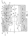
- FIG. 1 shows a first preferred embodiment of the magnetic resonance imaging (MRI) magnet 10 of the present invention.
- the magnet 10 includes a annularly cylindrical-shaped vacuum enclosure 12 having a longitudinally extending axis 14, first and second longitudinal ends 16 and 18, a first bore 20, and a second bore 22.
- the first bore 20 is generally coaxially aligned with the axis 14, extends with a constant radius from the first longitudinal end 16 towards the second longitudinal end 18, and is spaced apart from the second longitudinal end 18.
- the second bore 22 is coaxially aligned with the axis 14 and extends with a constant radius from the second longitudinal end 18 to the first bore 20, with the radius of the second bore 22 being smaller than the radius of the first bore 20.
- the longitudinal distance the first bore 20 extends from the first longitudinal end 16 does not exceed the longitudinal distance separating the first bore 20 from the second longitudinal end 18.
- the longitudinal distance the first bore 20 extends from the first longitudinal end 16 also is smaller than the longitudinal distance separating the first bore 20 from the second longitudinal end 18.
- the magnet 10 also includes a plurality of longitudinally spaced-apart superconductive coils 24a to 24f coaxially aligned with the axis 14 and disposed within and spaced apart from the vacuum enclosure 12.
- the superconductive coils 24a to 24f including a first coil 24a and a second coil 24b, each carry an electric current in the same direction (which is either a clockwise or a counterclockwise circumferential direction about the axis 14 with any slight longitudinal component of current direction being ignored).
- the first coil 24a circumferentially surrounds the first bore 20, and the second coil 24b circumferentially surrounds the second bore 22.
- the second coil 24b has a radially innermost portion 26, wherein the radial distance of the radially innermost portion 26 of the second coil 24b from the axis 14 is smaller than the radius of the first bore 20.
- the first coil 24a is disposed closer to the first longitudinal end 16 than to the second longitudinal end 18, and the second coil 24b is disposed closer to the second longitudinal end 18 than to the first longitudinal end 16.
- the first coil 24a is disposed proximate the first longitudinal end 16, and the second coil 24b is disposed proximate the second longitudinal end 18.
- the first and second coils 24a and 24b each extend a longitudinal length and a radial length, wherein the longitudinal length of the first coil 24a is greater than the radial length of the first coil 24a, and wherein the longitudinal length of the second coil 24b is greater than the radial length of the second coil 24b.
- the second coil 24b has a radially outermost portion 30, wherein the radial distance of the radially outermost portion 30 of the second coil 24b from the axis 14 is smaller than the radius of the first bore 20.
- the magnet 10 further includes a gradient coil 32 disposed in the second bore 22.
- the magnet 10 additionally includes a radio-frequency coil 36 disposed in the second bore 22 radially inward of the gradient coil 32.
- neither the gradient coil 32 nor the radio-frequency coil 36 extends into the first bore 20. It is noted that in Figure 1, the gradient coil 32 is schematically shown as contacting the vacuum enclosure 12 and the radio-frequency coil 36 is schematically shown as contacting the gradient coil 32.
- an MRI magnet typically may also include passive shims, a gradient shield, and a gap between the vacuum enclosure 12 and the gradient coil 32, and typically may also include a radio-frequency shield and a gap between the gradient coil 32 and the radio-frequency coil 36 (such shims, shields, and gaps not shown in the figures for clarity).
- the gradient shield may be omitted if continuous metallic paths are avoided on and within the vacuum enclosure 12 for an eddy-current-free magnet 10.
- the magnet 10 may be used to image various parts of the human body, such as limbs, the magnet 10 preferably is designed specifically for high magnetic field MRI imaging of the human brain.
- the first and second bores 20 and 22 preferably are sized such that the first longitudinal end 16 fits over a patient's shoulders 40 with the patient's head 42 at least partially passing through the first bore 20 and extending into the second bore 22 and such that the second bore 22 has a diameter which is smaller than the width of the patient's shoulders 40.
- the term "patient” means an average-sized human adult patient with such size averaged over males and females, as can be determined by those skilled in the art.
- the patient's head 42 passes through the first bore 20.
- the superconductive coils 24a to 24f preferably are designed to generate a magnetic resonance imaging volume 44 (shown in dotted line) in the region of the patient's brain when the first longitudinal end 16 of the vacuum enclosure 12 is fitted over (i.e., surrounds and extends below) the patient's shoulders 40 with the patient's head 42 at least partially passing through the first bore 20 and extending into the second bore 22.
- the superconductive coils 24a to 24f are designed to generate a magnetic resonance imaging volume 44 which has a shape of a sphere having a center disposed in the second bore 22 and on the axis 14, and wherein such center is further disposed longitudinally equidistant from the first and second longitudinal ends 16 and 18 of the vacuum enclosure 12.
- a magnetic resonance imaging volume 44 which has a shape of a sphere having a center disposed in the second bore 22 and on the axis 14, and wherein such center is further disposed longitudinally equidistant from the first and second longitudinal ends 16 and 18 of the vacuum enclosure 12.
- the entire spherical imaging volume 44 is disposed in the second bore 22.
- a magnet 10 having a 0.5 Tesla magnetic field within a 18-centimeter diameter spherical imaging volume 44 having a design peak-to-peak magnetic field inhomogeneity of less than 10 parts-per-million (ppm).
- the first bore 20 was designed to have a diameter of 53 centimeters
- the second bore 22 was designed to have a diameter of 35 centimeters
- the radio-frequency coil 36 was designed to have an inside diameter of 25 centimeters.
- the vacuum enclosure 12 had a longitudinal length of 62 centimeters, and the center of the spherical imaging volume 44 was positioned 32 centimeters from the first longitudinal end 16 of the vacuum enclosure 12. It is noted that the patient does not contact the vacuum enclosure 12.
- the superconductive coils 24a to 24f comprised a continuous (integral or spliced) length of 3mm (.12-inch) wide and 0.245mm (.01 inch) thick Nb-Si superconductive tape kept at a temperature of 10 Kelvin and carrying an electric current having an amperage of 214 amperes.
- the first coil 24a is longitudinally located 2 centimeters from the first longitudinal end 16 of the vacuum enclosure 12, is radially located 28 centimeters from the axis 14, extends a longitudinal length of 10 centimeters, extends a radial length of 1 centimeter, and has 470 meters of superconductive tape.
- the second coil 24b is longitudinally located 2 centimeters from the second longitudinal end 18 of the vacuum enclosure 12, is radially located 19 centimeters from the axis 14, extends a longitudinal length of 6 centimeters, extends a radial length of 1 centimeter, and has 360 meters of superconductive tape.
- the third coil 24c is longitudinally located 8 centimeters from the second coil 24b, is radially located 19 centimeters from the axis 14, extends a longitudinal length of 4 centimeters, extends a radial length of 0.5 centimeters, and has 134 meters of superconductive tape.
- the fourth coil 24d is longitudinally located 4 centimeters from the third coil 24c, is radially located 20 centimeters from the axis 14, extends a longitudinal length of 3 centimeters, extends a radial length of 0.5 centimeters, and has 94 meters of superconductive tape.
- the fifth coil 24e is longitudinally located 3 centimeters from the fourth coil 24d, is radially located 20 centimeters from the axis 14, extends a longitudinal length of 3 centimeters, extends a radial length of 0.5 centimeters, and has 81 meters of superconductive tape.
- the sixth coil 24f is longitudinally located 4 centimeters from the fifth coil 24e and 10 centimeters from the first coil 24a, is radially located 20 centimeters from the axis 14, extends a longitudinal length of 3 centimeters, extends a radial length of 0.5 centimeters, and has 78 meters of superconductive tape.
- the magnet 10 includes a coil form 54 supporting the superconductive coils 24a to 24f.
- the magnet 10 includes a thermal shield 56 disposed within and spaced apart from the vacuum enclosure 12, wherein the superconductive coils 24a to 24f are disposed within and spaced apart from the thermal shield 56.
- Conventional spacers space and support the coil form 54 from the thermal shield 56 and the thermal shield 56 from the vacuum enclosure 12.
- the magnet 10 is provided with a cryocooler coldhead 58 (such as a cryocooler coldhead of a Gifford-McMahon cryocooler) having a first stage 60 and a second stage 62, wherein the second stage 62 (which has a temperature of 10 Kelvin) is colder than the first stage 60 (which has a temperature of 40 Kelvin).
- the second stage 62 is in thermal contact with the superconductive coils 24a to 24f (by being in thermal contact with the coil form 54), and the first stage 60 is in thermal contact with the thermal shield 56.
- the coil form 54 comprises a glass reinforced epoxy composite wrapped with copper (or some other high thermal conductivity material)
- the thermal shield 56 comprises copper (or some other high thermal conductivity material)
- the vacuum enclosure 12 comprises a metal such as stainless steel.
- the coil form 54 and the thermal shield 56 each comprise a glass reinforced epoxy composite having copper (or some other high thermal conductivity material) wires or strips
- the vacuum enclosure 12 comprises a glass reinforced epoxy composite having some vapor barrier structure (such as stainless steel foils) embedded in it.
- the vacuum enclosure 12 comprises iron or any other magnetically shielding material to provide partial or complete shielding of the magnet's stray field.
- Such shielding makes the magnet 10 easier to site in a hospital room containing electronic equipment whose proper operation would be compromised by the magnet's stray field.
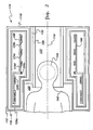
- FIG. 2 shows a second preferred embodiment of the magnetic resonance imaging (MRI) magnet 110 of the present invention.
- Magnet 110 of Figure 2 is similar to magnet 10 of Figure 1.
- Applicants designed (but have yet to build) such a magnet 110 having a 4.0 Tesla magnetic field within a 18-centimeter diameter spherical imaging volume 144 having a design peak-to-peak magnetic field inhomogeneity of less than 1 part-per-million (ppm).
- the first bore 120 was designed to have a diameter of 57 centimeters
- the second bore 122 was designed to have a diameter of 38 centimeters
- the radio-frequency coil 136 was designed to have an inside diameter of 28 centimeters.
- the vacuum enclosure 112 had a longitudinal length of 86 centimeters, and the center of the spherical imaging volume 144 was positioned 47 centimeters from the first longitudinal end 116 of the vacuum enclosure 112.
- the superconductive coils 124a to 124f comprise self-standing Nb-Ti superconductive coils operating at a temperature of generally 4 Kelvin with such coils 124a to 124f surrounded by an aluminum structure 166 for magnetic force containment.
- the gradient coil 132, the radio-frequency coil 136, and the imaging volume 144 are seen to extend into the first bore 120.
- a preferred mode of cooling a 4.0 Tesla magnet is to use: a liquid-helium dewar disposed outside, and hermetically connected to, the magnet; a thermal busbar having a first end disposed in the liquid helium and a second end in thermal contact with the superconductive coils; and a cryocooler coldhead mounted to the dewar with a cold stage extending downward to a point which is above and proximate the liquid helium to recondense liquid helium that was boiled-off in cooling the magnet.
- the compact design of the over-shoulder brain imaging MRI magnet 10 (or 110) of the embodiment achieves high magnetic field strength with low design magnetic field inhomogeneity by coil positioning.
- Low magnetic field inhomogeneity requires a large solid angle between a plane, passing through the center of the imaging volume 44 (or 144) perpendicular to the axis 14 (or 114), and each of the first and second coils 24a and 24b (or 124a and 124b).
- first coil 24a (or 124a) proximate the first longitudinal end 16 (or 116) of the vacuum enclosure 12 (or 112) and the second coil 24b (or 124b) proximate the second longitudinal end 18 (or 118) of the vacuum enclosure 12 (or 112) with the first coil 24a (or 124a) surrounding and extending below the patient's shoulders 40 (or 140).
- Such design techniques result in an MRI magnet 10 (or 110) with a high magnetic field strength for better MRI imaging.
- the patient is in a supine position on a medical examining table (not shown in the figures) which is brought to the MRI magnet 10 (or 110) to have the first longitudinal end 16 (or 116) of the vacuum enclosure 12 (or 112) be fitted over the patient's shoulders 40 (or 140).
- the superconductive coils 24a to 24f (or 124a to 124f) of the magnet 10 (or 110) of the invention are not limited to being cryocooler-cooled, and may be liquid-helium (or other liquid-cryogen) cooled. It is intended that the scope of the invention be defined by the claims appended hereto.
Landscapes
- Physics & Mathematics (AREA)
- Electromagnetism (AREA)
- Condensed Matter Physics & Semiconductors (AREA)
- General Physics & Mathematics (AREA)
- Magnetic Resonance Imaging Apparatus (AREA)
Applications Claiming Priority (2)
| Application Number | Priority Date | Filing Date | Title |
|---|---|---|---|
| US286364 | 1994-08-05 | ||
| US08/286,364 US5416415A (en) | 1994-08-05 | 1994-08-05 | Over-shoulder MRI magnet for human brain imaging |
Publications (3)
| Publication Number | Publication Date |
|---|---|
| EP0695949A2 EP0695949A2 (en) | 1996-02-07 |
| EP0695949A3 EP0695949A3 (OSRAM) | 1996-03-13 |
| EP0695949B1 true EP0695949B1 (en) | 2002-04-17 |
Family
ID=23098282
Family Applications (1)
| Application Number | Title | Priority Date | Filing Date |
|---|---|---|---|
| EP95304890A Expired - Lifetime EP0695949B1 (en) | 1994-08-05 | 1995-07-13 | MRI magnet |
Country Status (4)
| Country | Link |
|---|---|
| US (1) | US5416415A (OSRAM) |
| EP (1) | EP0695949B1 (OSRAM) |
| JP (1) | JP3706658B2 (OSRAM) |
| DE (1) | DE69526394T2 (OSRAM) |
Families Citing this family (48)
| Publication number | Priority date | Publication date | Assignee | Title |
|---|---|---|---|---|
| GB2295673B (en) * | 1994-11-29 | 1999-04-28 | Oxford Magnet Tech | Improvements in or relating to cryogenic mri magnets |
| US5721815A (en) * | 1995-06-07 | 1998-02-24 | International Business Machines Corporation | Media-on-demand communication system and method employing direct access storage device |
| JP3184763B2 (ja) | 1995-06-07 | 2001-07-09 | インターナショナル・ビジネス・マシーンズ・コーポレ−ション | マルチメディア直接アクセス記憶装置及びフォーマット方法 |
| US5799653A (en) * | 1995-10-03 | 1998-09-01 | Toshiba America Mri, Inc. | Magnetic resonance imaging apparatus with decreased patient claustrophobia and increased access to patient |
| US5818319A (en) * | 1995-12-21 | 1998-10-06 | The University Of Queensland | Magnets for magnetic resonance systems |
| US5651256A (en) * | 1996-05-31 | 1997-07-29 | General Electric Company | Superconductive magnet having a thermal shield |
| US5801609A (en) * | 1997-04-25 | 1998-09-01 | General Electric Company | MRI head magnet |
| GB2337595B (en) * | 1998-05-22 | 2003-03-19 | Oxford Magnet Tech | Improvements in or relating to magnetic resonance imaging systems |
| JP3702106B2 (ja) * | 1998-09-29 | 2005-10-05 | 株式会社東芝 | 磁気共鳴イメージング装置 |
| US6064290A (en) * | 1999-05-21 | 2000-05-16 | The Board Of Trustees Of The Leland Stanford Junior University | Short bore-length asymmetric electromagnets for magnetic resonance imaging |
| AUPQ198899A0 (en) * | 1999-08-03 | 1999-08-26 | University Of Queensland, The | A method of magnet design and magnet configuration |
| EP1074852B1 (en) * | 1999-08-03 | 2006-12-13 | NMR Holdings No. 2 Pty Limited | Method for designing a superconducting magnet |
| JP4565721B2 (ja) * | 2000-09-18 | 2010-10-20 | 株式会社日立メディコ | 超電導磁石装置、及びmri装置 |
| US6700468B2 (en) * | 2000-12-01 | 2004-03-02 | Nmr Holdings No. 2 Pty Limited | Asymmetric magnets for magnetic resonance imaging |
| US6954070B2 (en) * | 2003-01-06 | 2005-10-11 | Brk Wireless Company, Inc. | NMR imaging system with conical permanent magnet |
| US6807812B2 (en) * | 2003-03-19 | 2004-10-26 | Ge Medical Systems Global Technology Company, Llc | Pulse tube cryocooler system for magnetic resonance superconducting magnets |
| DE10352381B4 (de) * | 2003-11-10 | 2009-07-30 | Siemens Ag | Erzeuger zeitvariabler Magnetfelder eines Magnetresonanzgeräts und Magnetresonanzgerät mit dem Erzeuger |
| US7109708B2 (en) | 2004-08-19 | 2006-09-19 | General Electric Company | Systems, methods and apparatus of a magnetic resonance imaging magnet to produce an asymmetrical stray field |
| US7466133B2 (en) * | 2005-03-01 | 2008-12-16 | General Electric Company | Systems, methods and apparatus of a magnetic resonance imaging system to produce a stray field suitable for interventional use |
| US7375528B2 (en) * | 2005-03-29 | 2008-05-20 | Magnetica Limited | Shielded, asymmetric magnets for use in magnetic resonance imaging |
| US20070063801A1 (en) * | 2005-09-16 | 2007-03-22 | Laskaris Evangelos T | System and method for magnetic resonance imaging |
| AU2007308759B2 (en) | 2006-10-27 | 2011-05-12 | Nmr Holdings No. 2 Pty Limited | Magnets for use in magnetic resonance imaging |
| JP4921935B2 (ja) * | 2006-11-22 | 2012-04-25 | 株式会社日立製作所 | 電磁石装置及び磁気共鳴撮像装置 |
| JP5348870B2 (ja) * | 2006-11-24 | 2013-11-20 | 株式会社東芝 | Mri装置 |
| US8320647B2 (en) * | 2007-11-20 | 2012-11-27 | Olea Medical | Method and system for processing multiple series of biological images obtained from a patient |
| JP5224888B2 (ja) * | 2008-04-15 | 2013-07-03 | ジャパンスーパーコンダクタテクノロジー株式会社 | 超電導マグネットおよびそれを備えたマグネット装置 |
| MX2011011049A (es) * | 2009-04-20 | 2012-04-19 | Time Medical Holdings Company Ltd | Red de bobinas superconductores de radiofrecuencia enfriadas criogenicamente y sistema de imagenes resonancia magnetica solo para la cabeza con superconductores. |
| US20120258862A1 (en) | 2009-12-21 | 2012-10-11 | Nmr Holdings No. 2 Pty Limited | Open-bore magnet for use in magnetic resonance imaging |
| WO2013118117A1 (en) * | 2012-02-08 | 2013-08-15 | Anatech Advanced Nmr Algorithms Technologies Ltd | Method and system for inspection of composite material components |
| JP6266225B2 (ja) * | 2012-05-21 | 2018-01-24 | 東芝メディカルシステムズ株式会社 | 磁気共鳴イメージング装置及び磁気共鳴イメージング装置用の磁石 |
| JP6518194B2 (ja) * | 2012-12-26 | 2019-05-22 | コーニンクレッカ フィリップス エヌ ヴェKoninklijke Philips N.V. | アクセス可能な磁気共鳴撮像スキャナシステム及びソレノイド構造体 |
| WO2014155234A1 (en) * | 2013-03-28 | 2014-10-02 | Koninklijke Philips N.V. | Multi-zone radio-frequency coil array for variable patient sizes |
| ITTO20130307A1 (it) | 2013-04-17 | 2014-10-18 | Itt Italia Srl | Metodo per realizzare un elemento frenante, in particolare una pastiglia freno, sensorizzato, pastiglia freno sensorizzata, impianto frenante di veicolo e metodo associato |
| EP3183592B1 (en) * | 2014-08-18 | 2024-01-10 | Magnetica Limited | Magnet for head and extremity imaging |
| US9939035B2 (en) | 2015-05-28 | 2018-04-10 | Itt Italia S.R.L. | Smart braking devices, systems, and methods |
| ITUB20153706A1 (it) | 2015-09-17 | 2017-03-17 | Itt Italia Srl | Dispositivo frenante per veicolo pesante e metodo di prevenzione del surriscaldamento dei freni in un veicolo pesante |
| ITUB20153709A1 (it) | 2015-09-17 | 2017-03-17 | Itt Italia Srl | Dispositivo di analisi e gestione dei dati generati da un sistema frenante sensorizzato per veicoli |
| CN106908746B (zh) * | 2015-12-22 | 2020-01-21 | 通用电气公司 | 头部磁共振成像设备及其头部梯度线圈组件 |
| ITUA20161336A1 (it) | 2016-03-03 | 2017-09-03 | Itt Italia Srl | Dispositivo e metodo per il miglioramento delle prestazioni di un sistema antibloccaggio e antiscivolamento di un veicolo |
| IT201600077944A1 (it) | 2016-07-25 | 2018-01-25 | Itt Italia Srl | Dispositivo per il rilevamento della coppia residua di frenatura in un veicolo equipaggiato con freni a disco |
| EP3349028A1 (de) * | 2017-01-13 | 2018-07-18 | Sirona Dental Systems GmbH | Mrt-vorrichtung und verfahren zur vermessung eines kopfbereichs eines patienten |
| WO2018174726A2 (en) | 2017-03-24 | 2018-09-27 | Victoria Link Limited | Mri magnet and apparatus |
| EP3783345B1 (en) * | 2018-09-28 | 2023-11-01 | Nippon Steel Corporation | Magnet unit for nuclear magnetic resonance and magnetic field generating device for nuclear magnetic resonance |
| CN113544525B (zh) * | 2018-12-13 | 2024-10-25 | 麦格尼提卡有限公司 | 梯度线圈系统 |
| CN113366328A (zh) | 2019-02-12 | 2021-09-07 | 麦格尼提卡有限公司 | 磁体和磁共振成像系统 |
| IT201900015839A1 (it) | 2019-09-06 | 2021-03-06 | Itt Italia Srl | Pastiglia freno per veicoli e suo processo di produzione |
| WO2021149156A1 (ja) | 2020-01-21 | 2021-07-29 | 三菱電機株式会社 | 超電導コイル及び超電導コイルの製造方法 |
| US20240241003A1 (en) | 2021-05-25 | 2024-07-18 | Itt Italia S.R.L. | A method and a device for estimating residual torque between the braked and braking elements of a vehicle |
Family Cites Families (8)
| Publication number | Priority date | Publication date | Assignee | Title |
|---|---|---|---|---|
| US4500860A (en) * | 1984-07-05 | 1985-02-19 | General Electric Company | Winding support and method for NMR magnet axisymmetric correction coils |
| GB8500248D0 (en) * | 1985-01-04 | 1985-02-13 | Oxford Magnet Tech | Solenoids |
| US4724412A (en) * | 1987-08-03 | 1988-02-09 | General Electric Company | Method of determining coil arrangement of an actively shielded magnetic resonance magnet |
| US4924198A (en) * | 1988-07-05 | 1990-05-08 | General Electric Company | Superconductive magnetic resonance magnet without cryogens |
| US4986078A (en) * | 1989-08-17 | 1991-01-22 | General Electric Company | Refrigerated MR magnet support system |
| DE4010032C2 (de) * | 1990-03-29 | 1994-03-03 | Bruker Analytische Messtechnik | Magnetsystem |
| JPH05228125A (ja) * | 1992-02-21 | 1993-09-07 | Toshiba Corp | 磁気共鳴イメージング装置 |
| US5307039A (en) * | 1992-09-08 | 1994-04-26 | General Electric Company | Frustoconical magnet for magnetic resonance imaging |
-
1994
- 1994-08-05 US US08/286,364 patent/US5416415A/en not_active Expired - Fee Related
-
1995
- 1995-07-13 DE DE69526394T patent/DE69526394T2/de not_active Expired - Lifetime
- 1995-07-13 EP EP95304890A patent/EP0695949B1/en not_active Expired - Lifetime
- 1995-08-01 JP JP19565095A patent/JP3706658B2/ja not_active Expired - Fee Related
Also Published As
| Publication number | Publication date |
|---|---|
| US5416415A (en) | 1995-05-16 |
| EP0695949A3 (OSRAM) | 1996-03-13 |
| EP0695949A2 (en) | 1996-02-07 |
| DE69526394D1 (de) | 2002-05-23 |
| JP3706658B2 (ja) | 2005-10-12 |
| JPH08168476A (ja) | 1996-07-02 |
| DE69526394T2 (de) | 2002-11-07 |
Similar Documents
| Publication | Publication Date | Title |
|---|---|---|
| EP0695949B1 (en) | MRI magnet | |
| EP0695948B1 (en) | MRI magnet | |
| EP0874247B1 (en) | MRI head magnet | |
| US5428292A (en) | Pancake MRI magnet with modified imaging volume | |
| US5677630A (en) | Planar superconducting MRI magnet | |
| US5410287A (en) | Open MRI magnet with uniform magnetic field | |
| JP3673556B2 (ja) | 超伝導遮蔽体を設けた開放型磁気共鳴イメージング磁石 | |
| EP0773565B1 (en) | Cryogen-cooled open MRI superconductive magnet | |
| US5721523A (en) | Compact MRI superconducting magnet | |
| JPH11283824A (ja) | 遮蔽付き開放型超伝導磁石 | |
| GB2354076A (en) | Superconductive magnet with cryogenically cooled pole piece | |
| US5696476A (en) | Open architecture magnetic resonance imaging superconducting magnet assembly | |
| US5594401A (en) | Closed superconductive magnet with uniform imaging volume | |
| US6965236B2 (en) | MRI system utilizing supplemental static field-shaping coils | |
| US5568110A (en) | Closed MRI magnet having reduced length | |
| EP0770882B1 (en) | Open MRI superconductive magnet with cryogenic-fluid cooling | |
| US5568102A (en) | Closed superconductive magnet with homogeneous imaging volume | |
| US5521571A (en) | Open MRI magnet with uniform imaging volume | |
| US5431164A (en) | Therapy tomograph | |
| EP0826978A1 (en) | Closed MRI magnet having compact design | |
| JPH11318857A (ja) | 開放型磁石 |
Legal Events
| Date | Code | Title | Description |
|---|---|---|---|
| PUAI | Public reference made under article 153(3) epc to a published international application that has entered the european phase |
Free format text: ORIGINAL CODE: 0009012 |
|
| PUAL | Search report despatched |
Free format text: ORIGINAL CODE: 0009013 |
|
| AK | Designated contracting states |
Kind code of ref document: A2 Designated state(s): DE GB NL |
|
| AK | Designated contracting states |
Kind code of ref document: A3 Designated state(s): DE GB NL |
|
| 17P | Request for examination filed |
Effective date: 19960913 |
|
| 17Q | First examination report despatched |
Effective date: 19980209 |
|
| GRAG | Despatch of communication of intention to grant |
Free format text: ORIGINAL CODE: EPIDOS AGRA |
|
| GRAG | Despatch of communication of intention to grant |
Free format text: ORIGINAL CODE: EPIDOS AGRA |
|
| GRAH | Despatch of communication of intention to grant a patent |
Free format text: ORIGINAL CODE: EPIDOS IGRA |
|
| REG | Reference to a national code |
Ref country code: GB Ref legal event code: IF02 |
|
| GRAH | Despatch of communication of intention to grant a patent |
Free format text: ORIGINAL CODE: EPIDOS IGRA |
|
| GRAA | (expected) grant |
Free format text: ORIGINAL CODE: 0009210 |
|
| AK | Designated contracting states |
Kind code of ref document: B1 Designated state(s): DE GB NL |
|
| REF | Corresponds to: |
Ref document number: 69526394 Country of ref document: DE Date of ref document: 20020523 |
|
| PLBE | No opposition filed within time limit |
Free format text: ORIGINAL CODE: 0009261 |
|
| STAA | Information on the status of an ep patent application or granted ep patent |
Free format text: STATUS: NO OPPOSITION FILED WITHIN TIME LIMIT |
|
| 26N | No opposition filed |
Effective date: 20030120 |
|
| PGFP | Annual fee paid to national office [announced via postgrant information from national office to epo] |
Ref country code: DE Payment date: 20131230 Year of fee payment: 19 Ref country code: GB Payment date: 20131227 Year of fee payment: 19 |
|
| PGFP | Annual fee paid to national office [announced via postgrant information from national office to epo] |
Ref country code: NL Payment date: 20131226 Year of fee payment: 19 |
|
| REG | Reference to a national code |
Ref country code: DE Ref legal event code: R119 Ref document number: 69526394 Country of ref document: DE |
|
| REG | Reference to a national code |
Ref country code: NL Ref legal event code: V1 Effective date: 20150201 |
|
| GBPC | Gb: european patent ceased through non-payment of renewal fee |
Effective date: 20140713 |
|
| PG25 | Lapsed in a contracting state [announced via postgrant information from national office to epo] |
Ref country code: NL Free format text: LAPSE BECAUSE OF NON-PAYMENT OF DUE FEES Effective date: 20150201 |
|
| PG25 | Lapsed in a contracting state [announced via postgrant information from national office to epo] |
Ref country code: DE Free format text: LAPSE BECAUSE OF NON-PAYMENT OF DUE FEES Effective date: 20150203 |
|
| REG | Reference to a national code |
Ref country code: DE Ref legal event code: R119 Ref document number: 69526394 Country of ref document: DE Effective date: 20150203 |
|
| PG25 | Lapsed in a contracting state [announced via postgrant information from national office to epo] |
Ref country code: GB Free format text: LAPSE BECAUSE OF NON-PAYMENT OF DUE FEES Effective date: 20140713 |