EP0695900B1 - Passage étanche pour câble de télécommunications - Google Patents
Passage étanche pour câble de télécommunications Download PDFInfo
- Publication number
- EP0695900B1 EP0695900B1 EP95401775A EP95401775A EP0695900B1 EP 0695900 B1 EP0695900 B1 EP 0695900B1 EP 95401775 A EP95401775 A EP 95401775A EP 95401775 A EP95401775 A EP 95401775A EP 0695900 B1 EP0695900 B1 EP 0695900B1
- Authority
- EP
- European Patent Office
- Prior art keywords
- cable
- seal
- housing
- cable clamp
- duct according
- Prior art date
- Legal status (The legal status is an assumption and is not a legal conclusion. Google has not performed a legal analysis and makes no representation as to the accuracy of the status listed.)
- Expired - Lifetime
Links
- 230000000295 complement effect Effects 0.000 claims description 10
- 238000007789 sealing Methods 0.000 claims description 6
- 230000000284 resting effect Effects 0.000 claims description 2
- 230000037431 insertion Effects 0.000 claims 1
- 238000003780 insertion Methods 0.000 claims 1
- 239000013307 optical fiber Substances 0.000 description 7
- 239000004020 conductor Substances 0.000 description 4
- 239000000835 fiber Substances 0.000 description 3
- 230000006835 compression Effects 0.000 description 2
- 238000007906 compression Methods 0.000 description 2
- 210000000056 organ Anatomy 0.000 description 2
- 230000035515 penetration Effects 0.000 description 2
- 239000011347 resin Substances 0.000 description 2
- 229920005989 resin Polymers 0.000 description 2
- 238000000926 separation method Methods 0.000 description 2
- 241001415961 Gaviidae Species 0.000 description 1
- 238000005452 bending Methods 0.000 description 1
- 230000000903 blocking effect Effects 0.000 description 1
- 239000000470 constituent Substances 0.000 description 1
- 230000000694 effects Effects 0.000 description 1
- 229920001971 elastomer Polymers 0.000 description 1
- 239000000806 elastomer Substances 0.000 description 1
- 239000000463 material Substances 0.000 description 1
- 239000002184 metal Substances 0.000 description 1
- 238000012986 modification Methods 0.000 description 1
- 230000004048 modification Effects 0.000 description 1
- 230000000149 penetrating effect Effects 0.000 description 1
- 230000000750 progressive effect Effects 0.000 description 1
- 230000002787 reinforcement Effects 0.000 description 1
- 238000005728 strengthening Methods 0.000 description 1
- 238000006467 substitution reaction Methods 0.000 description 1
- 229920003051 synthetic elastomer Polymers 0.000 description 1
- 239000005061 synthetic rubber Substances 0.000 description 1
- 229920001187 thermosetting polymer Polymers 0.000 description 1
- 230000007704 transition Effects 0.000 description 1
Images
Classifications
-
- G—PHYSICS
- G02—OPTICS
- G02B—OPTICAL ELEMENTS, SYSTEMS OR APPARATUS
- G02B6/00—Light guides; Structural details of arrangements comprising light guides and other optical elements, e.g. couplings
- G02B6/44—Mechanical structures for providing tensile strength and external protection for fibres, e.g. optical transmission cables
- G02B6/4401—Optical cables
- G02B6/4415—Cables for special applications
- G02B6/4427—Pressure resistant cables, e.g. undersea cables
- G02B6/4428—Penetrator systems in pressure-resistant devices
-
- G—PHYSICS
- G02—OPTICS
- G02B—OPTICAL ELEMENTS, SYSTEMS OR APPARATUS
- G02B6/00—Light guides; Structural details of arrangements comprising light guides and other optical elements, e.g. couplings
- G02B6/44—Mechanical structures for providing tensile strength and external protection for fibres, e.g. optical transmission cables
- G02B6/4439—Auxiliary devices
- G02B6/4471—Terminating devices ; Cable clamps
- G02B6/44775—Cable seals e.g. feed-through
-
- H—ELECTRICITY
- H02—GENERATION; CONVERSION OR DISTRIBUTION OF ELECTRIC POWER
- H02G—INSTALLATION OF ELECTRIC CABLES OR LINES, OR OF COMBINED OPTICAL AND ELECTRIC CABLES OR LINES
- H02G15/00—Cable fittings
- H02G15/013—Sealing means for cable inlets
-
- H—ELECTRICITY
- H02—GENERATION; CONVERSION OR DISTRIBUTION OF ELECTRIC POWER
- H02G—INSTALLATION OF ELECTRIC CABLES OR LINES, OR OF COMBINED OPTICAL AND ELECTRIC CABLES OR LINES
- H02G3/00—Installations of electric cables or lines or protective tubing therefor in or on buildings, equivalent structures or vehicles
- H02G3/02—Details
- H02G3/08—Distribution boxes; Connection or junction boxes
- H02G3/088—Dustproof, splashproof, drip-proof, waterproof, or flameproof casings or inlets
Definitions
- the present invention relates to a sealed passage removable through a telecommunications cable, in particular to optical fibers, allowing to realize depending on the length of it connections, splices or other external connections with accessories or connections, to be connected to the cable conductors considered.
- connection box used to sealing between two opposite cable elements to assemble inside this case, especially when these cable elements are placed under a pressure of given gas, to keep the conductors immobilized and especially the optical fibers of these cable elements at their entrances into the case, and to moor and block in place these elements, especially when these include, with optical fibers, means independent sheath reinforcement and protection of the cable and a fiber support member, giving the cable with appropriate mechanical rigidity.
- This case must further allow to intervene on cables at various times, at separate times in time, with at each time opening and closing of the case, this without interrupting or disrupting signal traffic routed by optical fibers.
- the present invention relates to a sealed passage for telecommunications cable, the structure of which provides many advantages over solutions conventional (see, for example, WO-A-93 15 346) in which the end of the element of cable that enters the housing is generally housed in a split tube, which receives an appropriate amount of a thermosetting resin, this tube passing through a opening for penetration into the housing formed by two parts joined together, which traps between them, around the tube a seal.
- the sealed passage according to the invention aims in particular to provide better resistance at the end of the cable penetrating into the housing vis-à-vis the efforts of bending and pulling on it without harming the tightness of the case, while improving its slip resistance compared to the latter.
- the watertight passage proposed is also easy to assemble and to disassemble, does not require any technicality for this purpose specific for the user and provides a seal effective even at high pressures inside the cable sheath, up to up to 2 bars, this tightness is now equal to itself in time.
- the invention avoiding the use of resin blocks cast, in a classic split tube, also allows easy cable replacement and also allows the use of already existing boxes, reducing by consequently considerably the cost price of the passage waterproof obtained.
- the sealed passage crossed by a telecommunications cable considered comprising a housing formed of two parts suitable for being secured against each other, with compression between them of a flat seal extending along a plan common to both parts, these delimiting between they an internal region into which is introduced the end of at least one cable through an opening access provided laterally in the box between the two parts of it, is characterized in that it comprises, surrounding the cable and arranged according to the dimension longitudinal to the right of the orifice, from the outside towards inside the case, a cable clamp in at least two additional parts trapping the cable, a seal crossed by the cable, preferably cross-section cylindrical, placed behind the cable clamp, and an organ presser, also in at least two parts complementary, arranged between the cable clamp and the seal and applied against the back side of it, this member being capable of exerting on the cable joint a axial force by the effect of a thrust member taking support on the cable clamp.
- the cable joint has two lips longitudinal sides, projecting on either side of the joint, engaging between the two complementary parts of the cable clamp and arranged in the common plane containing the flat gasket between the two parts of the housing.
- the cable joint has two side grooves, diametrically opposite, where engages the flat seal.
- the cable joint has a slot longitudinal separation, so as to allow this joint to be placed around the cable without requiring put it on this one.
- the slot longitudinal presents a part in ⁇ to facilitate the connection of the two edges of the joint, on either side of the separation slot.
- the cable clamp, the pressing member and the cable seal are housed at the inside of a two-part guide tube, open at its ends and engaged in the hole access to the interior of the housing, this tubing comprising two parallel transverse shoulders, support on the opposite faces of the housing, directed respectively inward and outward thereof, the thickness of the housing between these faces being substantially equal to the length of the tubing between its shoulders.
- a transverse pin or the like perpendicular to the axis of the guide tube, secures it with the cable clamp, so avoid its relative rotation relative to the housing.
- the cable clamp, the pressing member and the cable seal are housed in an open cavity formed in the thickness of the housing, whose bottoms are delimited by parallel faces against which the seal respectively bear and the cable clamp, one of said faces outwards of the housing, constituting the pressure member of the seal.
- the two complementary parts of the cable clamp are brought towards each other to immobilize the cable by connecting screws, arranged in threaded passages of the cable clamp extending perpendicular to the direction of the cable.
- the organ of thrust includes at least one screw passing through a bore threaded cable clamp, provided parallel to the direction of the cable and the end of which is applied to the pressing member so as to exert on it the effort required for a limited crushing of the joint to inside the access hole of the housing.
- the flat seal of the housing has a ring-shaped part, arranged in the access hole inside the housing the cable, this ring surrounding the tubing as appropriate guide or cable joint directly inside from the open cavity of the housing.
- the cable clamp, the pressure member and the seal cylindrical may have a plurality of bores for mounting as many separate cables, these bores with parallel axial directions between them.
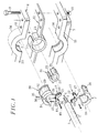
- the end of the cable 1 is intended to engage and come to a stop inside an access orifice 5, formed between two parts, respectively 6 and 7, of a housing 8, these two parts being capable of apply against each other before being immobilized in this position by means of a set of screws 9, blocked by nuts 10 after passing through holes 11 formed in the edges of these two parts 6 and 7.
- a flat seal 12 is preferably mounted between the two parts 6 and 7 according to their periphery, and extends in their common junction plane by applying against the facing faces of these two parts of the housing.
- the seal 12, of a suitable elastomer material of the kind synthetic rubber includes a running part 13 in the form of a ribbon and, to the right of the access orifice 5 by which the end of the cable 1 penetrates inside the housing, a ring 14 conforming to the outline of this orifice.
- the immobilization of the cable vis-à-vis the housing in the orifice 5 and the sealing of the passage thus achieved are obtained by the combination of three pieces which together perform the functions necessary to obtain the desired result.
- These three pieces are notably constituted by a greenhouse cable 15, a cylindrical seal 16 and a pressing member 17, these three elements being arranged around the cable 1 inside the orifice 5 of the next way.
- the cable clamp 15 consists of two parts complementary, respectively 18 and 19, suitable to come tighten the cable from the outside of its sheath 2, being brought together by means of clamping screws 20 crossing one of the parts 18 through holes shouldered 21 and coming to engage their threaded end in a threaded bore 22 of the other part 19, in order to exert on these two pieces an effort of approximation up to sheath locking with adjustable force, remaining less than that which could damage the optical fibers 4 housed inside the cable.
- the seal 16 has a general shape cylindrical and with a body 23 and an internal recess 24 for cable passage 1. If necessary, the seal 16 can have lips on its outer surface 25, allowing this joint to be maintained between the two complementary parts 18 and 19 of the cable clamp 15.
- the pressing member 17 is in the form of a metal washer, also in two parts 26 and 27, like the parts 18 and 19 of the cable clamp 15, the member presser being housed around cable 1 between this clamp cable and the seal 16 which follows.
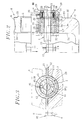
- the assembly formed by the cable clamp 15, the seal cylindrical 16 and the pressing member 17, is housed in the access port 5 inside the housing 8 by through a guide element 28, in the form of tubing, again made in two parts, 29 and 30 respectively.
- Each of these parts has at its ends a flat shoulder, respectively 31 and 32, able to come and stand against the external face 33 on the one hand, against the internal face 34 on the other hand, of on either side of the ends of the access orifice 5 in thus resting on the edges of the case, the distance which separates the shoulders 31 and 32 corresponding substantially to the thickness of the wall of this housing, as seen more particularly in the view in section of Figure 2.
- a transverse pin 35 passes through a hole 36 of one 29 of the two parts of the tubing 28 to come engage in a receiving hole 37 provided in the facing piece 18 of the cable clamp 15, in order to secure this one with the tubing and prevent its rotation relative to the housing.
- a thrust member constituted by one or more screws such as 38, engaged in a hole threaded 39 opposite the cable clamp 15, the control for this screw through its head 40, allowing to exert on the presser 17 located on the opposite side opposite of the cable clamp an effort achieving compression progressive of the cylindrical seal 16, between this presser and the shoulder 32 of the tube 28 located on the opposite side.
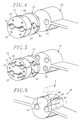
- the cable clamp 15, the cylindrical seal 16 and the pressing member 17 are designed to allow introduction through the access port 5 in the housing 8 of a single cable.
- these various components of the watertight passage can be designed so as to ensure the crossing of this passage by two parallel cables, the two parts 18 and 19 of the greenhouse cable or presser 26 and 27 with two notches semi-cylindrical neighbors 41 for the reception of these cables separately, the cylindrical joint 16 having two recesses 24 facing each other.
- the same parts are this time planned to allow the passage of four parallel cables, the cable clamp 15 and the pressing member 17 here being produced in three parts, 42 and 43 respectively at the ends, on the part and other of a central part 44, each of them comprising as in the previous variant notches semi-cylindrical 41 crossed by these cables.
- the cylindrical seal 16 in this case has four 24 corresponding recesses.
- the cable clamp 15 and the multi-part pressing member 17 can be easily adapted on both sides of the cables 1 to be immobilized tightly during their penetration inside the case.
- the cylindrical seal 16, the latter if it is formed in one piece, requires it to be threaded on the end of the cable, which can be problematic and in particular risk of damaging the optical fibers exceeding this.
- each slot 45 spares 45, extending to the recesses 24 reserved for the passage of these cables, so as to open laterally the joint, to mount the corresponding cable, then to close by reconstituting the joint itself.
- the facing edges of each slot 45 have a notch 46 for one, part in projection 47 for the other, preferably at n, in order to allow to join these edges in the manner of a buttonhole.
- cylindrical seal 16 is directly connected to the flat seal 12 housed between the two parts of the housing, in arranging the sides of the cable joint so that they have grooves or other hollow parts allowing the sides of the flat seal to engage, ensuring the continuity of the necessary seal on the periphery of this case.
- the flat seal 12 of the housing can therefore be integral with or separate from the cable joint 16; furthermore, this the latter may have a different section, the orifice access 5 provided between the two parts of the housing can be made in "wells" in one of these parts, the other in the form of a flat cover closing the upper part of this well, this solution having the advantage of avoiding any possibility of rotation relative of the cable immobilized inside the joint by report to the housing.
- the seal 12 disposed between the two parts of the latter can be produced otherwise than in the form of a flat ribbon, by example with a toric or prismatic section.
- the housing receiving a or more cables also has one or more other access holes not occupied by the ends of such cables, in which case each of these passages can be equipped with a cimblot which temporarily seals it and be easily removed to make room for a cable. complementary when the time comes.
Landscapes
- Physics & Mathematics (AREA)
- General Physics & Mathematics (AREA)
- Optics & Photonics (AREA)
- Engineering & Computer Science (AREA)
- Architecture (AREA)
- Civil Engineering (AREA)
- Structural Engineering (AREA)
- Cable Accessories (AREA)
- Installation Of Indoor Wiring (AREA)
Applications Claiming Priority (2)
| Application Number | Priority Date | Filing Date | Title |
|---|---|---|---|
| FR9409590A FR2723419A1 (fr) | 1994-08-02 | 1994-08-02 | Dispositif pour passage etanche pour cables ou analogues |
| FR9409590 | 1994-08-02 |
Publications (2)
| Publication Number | Publication Date |
|---|---|
| EP0695900A1 EP0695900A1 (fr) | 1996-02-07 |
| EP0695900B1 true EP0695900B1 (fr) | 1998-07-01 |
Family
ID=9466003
Family Applications (1)
| Application Number | Title | Priority Date | Filing Date |
|---|---|---|---|
| EP95401775A Expired - Lifetime EP0695900B1 (fr) | 1994-08-02 | 1995-07-26 | Passage étanche pour câble de télécommunications |
Country Status (4)
| Country | Link |
|---|---|
| EP (1) | EP0695900B1 (enExample) |
| DE (1) | DE69503195T2 (enExample) |
| ES (1) | ES2117367T3 (enExample) |
| FR (1) | FR2723419A1 (enExample) |
Cited By (1)
| Publication number | Priority date | Publication date | Assignee | Title |
|---|---|---|---|---|
| US20240421581A1 (en) * | 2023-06-13 | 2024-12-19 | Ampthink, Llc | Cable gland assembly |
Families Citing this family (15)
| Publication number | Priority date | Publication date | Assignee | Title |
|---|---|---|---|---|
| FR2757598B1 (fr) * | 1996-12-23 | 1999-03-05 | Pouyet Sa | Joint destine a etre dispose circonferentiellement autour d'un element globalement cylindrique |
| JPH10336867A (ja) * | 1997-06-03 | 1998-12-18 | Japan Riicom:Kk | ケーブル接続用クロージャ |
| FR2775845B1 (fr) * | 1998-03-09 | 2000-04-14 | Alsthom Cge Alcatel | Boitier etanche d'appareillage a acces pour cable |
| FR2780132B1 (fr) | 1998-06-23 | 2002-04-19 | Pirelli Cables Sa | Croisement entre un joint rond et un joint plat |
| US6180882B1 (en) * | 1999-01-19 | 2001-01-30 | Thomas & Betts, International | Single and dual cable seal system |
| BE1014083A5 (nl) * | 2000-10-12 | 2003-04-01 | Belcon N V | Huisvormige inrichting voor het isoleren van een vezelbundel, in het bijzonder glasvezel. |
| AU2002325719A1 (en) * | 2001-09-06 | 2003-03-18 | Trillium Photonics Inc. | Removable fiber strain relief and locking apparatus |
| FR2880478A1 (fr) * | 2005-01-04 | 2006-07-07 | France Telecom | Dispositif de raccordement etanche de cables de telecommunications et son procede de fabrication |
| US7186929B2 (en) * | 2005-07-08 | 2007-03-06 | 3M Innovative Properties Company | Sealing member for an entry port |
| JP5600521B2 (ja) * | 2010-08-25 | 2014-10-01 | パナソニック株式会社 | 給電制御装置 |
| DE202011000707U1 (de) | 2011-03-29 | 2011-09-07 | Zellner Gmbh | Fluiddichte Zugentlastung |
| EP2994966A1 (en) * | 2013-05-09 | 2016-03-16 | Tyco Electronics Raychem BVBA | Sealing block with stackable sealing element |
| DE102013017434B4 (de) * | 2013-10-18 | 2024-07-11 | Gabo Systemtechnik Gmbh | Dichtungsscheibe |
| CN105785531B (zh) * | 2016-04-27 | 2019-08-02 | 武汉瑞联光通信技术有限公司 | 一种通讯光缆接线盒 |
| CN113093354B (zh) * | 2021-03-31 | 2023-02-28 | 国网安徽省电力有限公司旌德县供电公司 | 基于光缆余缆专用的防动物啃咬装置 |
Family Cites Families (6)
| Publication number | Priority date | Publication date | Assignee | Title |
|---|---|---|---|---|
| DE311576C (enExample) * | ||||
| US2493556A (en) * | 1947-12-20 | 1950-01-03 | Standard Oil Dev Co | Supporting and sealing member |
| US4634206A (en) * | 1984-09-19 | 1987-01-06 | Harting Elektronik Gmbh | Apparatus for inserting a flat cable |
| DE3833370A1 (de) * | 1988-09-29 | 1990-04-12 | Siemens Ag | Loesbare mediendichte durchfuehrung |
| GB9201557D0 (en) * | 1992-01-24 | 1992-03-11 | Rose Walter Gmbh & Co Kg | Sealing arrangement |
| DE9208255U1 (de) * | 1992-06-20 | 1992-09-03 | Doyma-Rohrdurchführungstechnik Hans-Ullrich Ihlenfeldt, 2806 Oyten | Rohr-Dichtungseinsatz |
-
1994
- 1994-08-02 FR FR9409590A patent/FR2723419A1/fr active Granted
-
1995
- 1995-07-26 ES ES95401775T patent/ES2117367T3/es not_active Expired - Lifetime
- 1995-07-26 DE DE69503195T patent/DE69503195T2/de not_active Expired - Fee Related
- 1995-07-26 EP EP95401775A patent/EP0695900B1/fr not_active Expired - Lifetime
Cited By (1)
| Publication number | Priority date | Publication date | Assignee | Title |
|---|---|---|---|---|
| US20240421581A1 (en) * | 2023-06-13 | 2024-12-19 | Ampthink, Llc | Cable gland assembly |
Also Published As
| Publication number | Publication date |
|---|---|
| DE69503195T2 (de) | 1998-11-26 |
| EP0695900A1 (fr) | 1996-02-07 |
| FR2723419B1 (enExample) | 1997-02-07 |
| FR2723419A1 (fr) | 1996-02-09 |
| DE69503195D1 (de) | 1998-08-06 |
| ES2117367T3 (es) | 1998-08-01 |
Similar Documents
| Publication | Publication Date | Title |
|---|---|---|
| EP0695900B1 (fr) | Passage étanche pour câble de télécommunications | |
| EP0808008B1 (fr) | Boítier étanche de raccordement de câbles | |
| EP0978745B1 (fr) | Dispositif d'entrée de câble à fibres optiques | |
| EP0039703B1 (fr) | Manchon pour proteger l'epissure de cables electriques ou telephoniques | |
| FR2762455A1 (fr) | Piece de raccordement etanche d'un tube a l'orifice d'une paroi | |
| EP0942507B1 (fr) | Boítier étanche d'appareillage à accés pour câble | |
| EP0243234A1 (fr) | Dispositif et procédé d'épanouissement de fibres optiques sortant d'un câble à raccorder | |
| EP0476024B1 (fr) | Connecteur pour fibres optiques | |
| EP2571113B1 (fr) | Dispositif de fixation et de connexion rapide pour connecteur en deux parties | |
| FR2776135A1 (fr) | Conduit associe a un conducteur electrique de detection, par exemple pour le tirage ou poussage d'un cable | |
| FR2694655A1 (fr) | Dispositif de traversée étanche d'une cloison par des câbles tels que des câbles électriques. | |
| FR3060101B1 (fr) | Dispositif de connexion de luminaire | |
| EP0373008B1 (fr) | Pièce de liaison destinée à l'assemblage de profilés | |
| EP0821835B1 (fr) | Dispositif de raccord arriere pour connecteur electrique pour cable blinde | |
| EP0050560B1 (fr) | Raccord pour flûte sismique avec connecteurs à plat | |
| FR2469782A1 (fr) | Manchon pour proteger l'epissure de cables electriques ou telephoniques | |
| FR2748128A1 (fr) | Dispositif de fixation destine a realiser une liaison rigide entre un verre optique et un element de monture de lunettes | |
| FR2727252A1 (fr) | Dispositif de connexion electrique | |
| FR3146377A3 (fr) | Elément de traversée d’une paroi de boîtier par un câble | |
| FR3156601A1 (fr) | Connecteur à perforation d’isolant | |
| FR2696555A1 (fr) | Boîtier de raccordement pour fibres optiques. | |
| FR2971634A1 (fr) | Connecteur de raccordement electrique comportant une enveloppe | |
| EP0490725A1 (fr) | Dispositif d'obturation d'un passage tubulaire de cable | |
| FR2642851A1 (fr) | Connecteur pour fibres optiques | |
| FR2479545A2 (fr) | Manchon pour proteger l'epissure de cables electriques ou telephoniques |
Legal Events
| Date | Code | Title | Description |
|---|---|---|---|
| PUAI | Public reference made under article 153(3) epc to a published international application that has entered the european phase |
Free format text: ORIGINAL CODE: 0009012 |
|
| AK | Designated contracting states |
Kind code of ref document: A1 Designated state(s): DE ES GB IT PT |
|
| 17P | Request for examination filed |
Effective date: 19960703 |
|
| 17Q | First examination report despatched |
Effective date: 19961219 |
|
| GRAG | Despatch of communication of intention to grant |
Free format text: ORIGINAL CODE: EPIDOS AGRA |
|
| GRAG | Despatch of communication of intention to grant |
Free format text: ORIGINAL CODE: EPIDOS AGRA |
|
| GRAH | Despatch of communication of intention to grant a patent |
Free format text: ORIGINAL CODE: EPIDOS IGRA |
|
| GRAH | Despatch of communication of intention to grant a patent |
Free format text: ORIGINAL CODE: EPIDOS IGRA |
|
| GRAA | (expected) grant |
Free format text: ORIGINAL CODE: 0009210 |
|
| ITF | It: translation for a ep patent filed | ||
| AK | Designated contracting states |
Kind code of ref document: B1 Designated state(s): DE ES GB IT PT |
|
| GBT | Gb: translation of ep patent filed (gb section 77(6)(a)/1977) |
Effective date: 19980703 |
|
| REG | Reference to a national code |
Ref country code: ES Ref legal event code: FG2A Ref document number: 2117367 Country of ref document: ES Kind code of ref document: T3 |
|
| REF | Corresponds to: |
Ref document number: 69503195 Country of ref document: DE Date of ref document: 19980806 |
|
| REG | Reference to a national code |
Ref country code: PT Ref legal event code: SC4A Free format text: AVAILABILITY OF NATIONAL TRANSLATION Effective date: 19980706 |
|
| PLBE | No opposition filed within time limit |
Free format text: ORIGINAL CODE: 0009261 |
|
| STAA | Information on the status of an ep patent application or granted ep patent |
Free format text: STATUS: NO OPPOSITION FILED WITHIN TIME LIMIT |
|
| 26N | No opposition filed | ||
| REG | Reference to a national code |
Ref country code: GB Ref legal event code: IF02 |
|
| PGFP | Annual fee paid to national office [announced via postgrant information from national office to epo] |
Ref country code: DE Payment date: 20050624 Year of fee payment: 11 |
|
| PGFP | Annual fee paid to national office [announced via postgrant information from national office to epo] |
Ref country code: GB Payment date: 20050627 Year of fee payment: 11 |
|
| PGFP | Annual fee paid to national office [announced via postgrant information from national office to epo] |
Ref country code: PT Payment date: 20050629 Year of fee payment: 11 |
|
| PGFP | Annual fee paid to national office [announced via postgrant information from national office to epo] |
Ref country code: ES Payment date: 20050707 Year of fee payment: 11 |
|
| PG25 | Lapsed in a contracting state [announced via postgrant information from national office to epo] |
Ref country code: IT Free format text: LAPSE BECAUSE OF NON-PAYMENT OF DUE FEES;WARNING: LAPSES OF ITALIAN PATENTS WITH EFFECTIVE DATE BEFORE 2007 MAY HAVE OCCURRED AT ANY TIME BEFORE 2007. THE CORRECT EFFECTIVE DATE MAY BE DIFFERENT FROM THE ONE RECORDED. Effective date: 20050726 |
|
| PG25 | Lapsed in a contracting state [announced via postgrant information from national office to epo] |
Ref country code: GB Free format text: LAPSE BECAUSE OF NON-PAYMENT OF DUE FEES Effective date: 20060726 |
|
| PG25 | Lapsed in a contracting state [announced via postgrant information from national office to epo] |
Ref country code: PT Free format text: LAPSE BECAUSE OF NON-PAYMENT OF DUE FEES Effective date: 20070126 |
|
| PG25 | Lapsed in a contracting state [announced via postgrant information from national office to epo] |
Ref country code: DE Free format text: LAPSE BECAUSE OF NON-PAYMENT OF DUE FEES Effective date: 20070201 |
|
| REG | Reference to a national code |
Ref country code: PT Ref legal event code: MM4A Free format text: LAPSE DUE TO NON-PAYMENT OF FEES Effective date: 20070126 |
|
| GBPC | Gb: european patent ceased through non-payment of renewal fee |
Effective date: 20060726 |
|
| REG | Reference to a national code |
Ref country code: ES Ref legal event code: FD2A Effective date: 20060727 |
|
| PG25 | Lapsed in a contracting state [announced via postgrant information from national office to epo] |
Ref country code: ES Free format text: LAPSE BECAUSE OF NON-PAYMENT OF DUE FEES Effective date: 20060727 |