EP0695899B1 - Stopfbuchspackung - Google Patents
Stopfbuchspackung Download PDFInfo
- Publication number
- EP0695899B1 EP0695899B1 EP95110220A EP95110220A EP0695899B1 EP 0695899 B1 EP0695899 B1 EP 0695899B1 EP 95110220 A EP95110220 A EP 95110220A EP 95110220 A EP95110220 A EP 95110220A EP 0695899 B1 EP0695899 B1 EP 0695899B1
- Authority
- EP
- European Patent Office
- Prior art keywords
- sealing body
- accordance
- sealing
- annular
- shaft
- Prior art date
- Legal status (The legal status is an assumption and is not a legal conclusion. Google has not performed a legal analysis and makes no representation as to the accuracy of the status listed.)
- Expired - Lifetime
Links
- 238000012856 packing Methods 0.000 title abstract description 19
- 238000007789 sealing Methods 0.000 claims abstract description 90
- 239000004753 textile Substances 0.000 claims abstract description 17
- 239000000463 material Substances 0.000 claims abstract description 12
- 239000006185 dispersion Substances 0.000 claims abstract description 10
- 238000000034 method Methods 0.000 claims abstract description 7
- 239000011148 porous material Substances 0.000 claims abstract description 7
- 238000003825 pressing Methods 0.000 claims abstract description 7
- 239000013543 active substance Substances 0.000 claims abstract description 6
- 229920001343 polytetrafluoroethylene Polymers 0.000 claims description 21
- 239000004810 polytetrafluoroethylene Substances 0.000 claims description 19
- 239000002245 particle Substances 0.000 claims description 9
- 230000000694 effects Effects 0.000 claims description 8
- 239000006260 foam Substances 0.000 claims description 7
- 229920002545 silicone oil Polymers 0.000 claims description 7
- 238000004519 manufacturing process Methods 0.000 claims description 5
- 238000005470 impregnation Methods 0.000 claims description 4
- 239000000314 lubricant Substances 0.000 claims description 4
- 239000007787 solid Substances 0.000 claims description 2
- 230000001413 cellular effect Effects 0.000 claims 4
- 241000826860 Trapezium Species 0.000 claims 1
- 238000001035 drying Methods 0.000 abstract description 3
- 238000005520 cutting process Methods 0.000 abstract description 2
- 239000006261 foam material Substances 0.000 abstract 1
- 239000004744 fabric Substances 0.000 description 12
- 239000000835 fiber Substances 0.000 description 12
- 210000004907 gland Anatomy 0.000 description 5
- -1 polytetrafluoroethylene Polymers 0.000 description 4
- 239000003566 sealing material Substances 0.000 description 4
- OKTJSMMVPCPJKN-UHFFFAOYSA-N Carbon Chemical compound [C] OKTJSMMVPCPJKN-UHFFFAOYSA-N 0.000 description 3
- 239000004734 Polyphenylene sulfide Substances 0.000 description 3
- 239000007788 liquid Substances 0.000 description 3
- 238000000465 moulding Methods 0.000 description 3
- 229920000728 polyester Polymers 0.000 description 3
- 229920000069 polyphenylene sulfide Polymers 0.000 description 3
- 239000004480 active ingredient Substances 0.000 description 2
- 239000011521 glass Substances 0.000 description 2
- 239000010439 graphite Substances 0.000 description 2
- 229910002804 graphite Inorganic materials 0.000 description 2
- 238000004806 packaging method and process Methods 0.000 description 2
- 238000003860 storage Methods 0.000 description 2
- 239000000126 substance Substances 0.000 description 2
- 101100008046 Caenorhabditis elegans cut-2 gene Proteins 0.000 description 1
- BPQQTUXANYXVAA-UHFFFAOYSA-N Orthosilicate Chemical compound [O-][Si]([O-])([O-])[O-] BPQQTUXANYXVAA-UHFFFAOYSA-N 0.000 description 1
- 239000004952 Polyamide Substances 0.000 description 1
- 239000004760 aramid Substances 0.000 description 1
- 229920006231 aramid fiber Polymers 0.000 description 1
- 229920003235 aromatic polyamide Polymers 0.000 description 1
- 239000010425 asbestos Substances 0.000 description 1
- 238000009954 braiding Methods 0.000 description 1
- 229910052799 carbon Inorganic materials 0.000 description 1
- 239000003795 chemical substances by application Substances 0.000 description 1
- 239000003245 coal Substances 0.000 description 1
- 239000002131 composite material Substances 0.000 description 1
- 230000006835 compression Effects 0.000 description 1
- 238000007906 compression Methods 0.000 description 1
- 238000010276 construction Methods 0.000 description 1
- 238000005260 corrosion Methods 0.000 description 1
- 230000007797 corrosion Effects 0.000 description 1
- 230000001419 dependent effect Effects 0.000 description 1
- 239000002657 fibrous material Substances 0.000 description 1
- 239000008187 granular material Substances 0.000 description 1
- 238000009434 installation Methods 0.000 description 1
- 238000005461 lubrication Methods 0.000 description 1
- 238000005259 measurement Methods 0.000 description 1
- 239000002184 metal Substances 0.000 description 1
- 239000002480 mineral oil Substances 0.000 description 1
- 239000004745 nonwoven fabric Substances 0.000 description 1
- 239000003921 oil Substances 0.000 description 1
- 239000005022 packaging material Substances 0.000 description 1
- 239000004033 plastic Substances 0.000 description 1
- 229920002647 polyamide Polymers 0.000 description 1
- 238000007639 printing Methods 0.000 description 1
- 230000000717 retained effect Effects 0.000 description 1
- 229910052895 riebeckite Inorganic materials 0.000 description 1
- 238000009958 sewing Methods 0.000 description 1
- 229910001220 stainless steel Inorganic materials 0.000 description 1
- 239000010935 stainless steel Substances 0.000 description 1
- 150000005846 sugar alcohols Polymers 0.000 description 1
- XLYOFNOQVPJJNP-UHFFFAOYSA-N water Substances O XLYOFNOQVPJJNP-UHFFFAOYSA-N 0.000 description 1
- 239000002759 woven fabric Substances 0.000 description 1
Images

Classifications
-
- F—MECHANICAL ENGINEERING; LIGHTING; HEATING; WEAPONS; BLASTING
- F16—ENGINEERING ELEMENTS AND UNITS; GENERAL MEASURES FOR PRODUCING AND MAINTAINING EFFECTIVE FUNCTIONING OF MACHINES OR INSTALLATIONS; THERMAL INSULATION IN GENERAL
- F16J—PISTONS; CYLINDERS; SEALINGS
- F16J15/00—Sealings
- F16J15/16—Sealings between relatively-moving surfaces
- F16J15/18—Sealings between relatively-moving surfaces with stuffing-boxes for elastic or plastic packings
- F16J15/20—Packing materials therefor
Definitions
- the invention relates to a device for sealing moving Parts, such as a shaft, using a stuffing box packing according to the preamble of claim 1 and a Process for producing the sealing body used as a packing.
- Stuffing box packings usually consist of special ones Cord or braid rings, as well as rings or washers made of plastic, coal, graphite, metal or various Granulate layers between the shaft and the corresponding housing wall arranged in an annular space are and against the wave, using the so-called fabric book glasses as well as pressed against the housing wall, whereby the Sealing is achieved.
- a method and an apparatus for sealing moving parts using glands for example described in DE-PS 34 45 805.
- sealing material which is corrosion and heat resistant and made textile material in the form of woven or non-woven fabric, as Braid or felt made including needle felt can be.
- the textile material with a dispersion impregnated, which contains PTFE parts by weight. It flange gaskets as well as fabric book packs are described, with cords expressly for packing be proposed from braid or the like, so that the Disadvantages already described above according to this known Proposal cannot be fixed.
- the object of the present invention is to provide a stuffing box packing to create not only good sealing properties, but also has good sliding properties and thereby is wear-resistant and low friction and energy losses having. This task is characterized by the features of the claim 1 solved.
- the invention is based on the knowledge that the shaft surface of the stuffing box in contact and even must be unstructured, as for example by the Cut surface of a cut textile or foam sheet given is. It can also store a high proportion of PTFE and be brought into effect so that good sliding properties and thus achieved low friction and energy losses can be.
- the sealing body 1 is composed of washers is, all the desired strengths and dimensions can be assemble the sealing body 1 in a simple manner.
- the shaft has a trapezoidal cross section, whereby the shorter trapezoidal side rests on the moving part.
- trapezoidal sealing body 1 in the annular gap be inserted so that there is a kind of throttling effect between the individual wedge-shaped sections.
- the sealing body 1 made of different fiber materials composed. Further details of the invention are described with reference to the drawings.
- Annular disks 11, 12, 13 are cut out of a fabric web, preferably punched out.
- the fabric web is preferably made of needle felt, since needle felt webs can not only be produced very economically, but can also be produced very variably in connection with a built-in carrier fabric, that is to say they can be produced in a manner that is closely adapted to the application requirements.
- Needle felts can be made from any textile fiber. Needle felts with a basis weight between 400 g to 3000 g per m 2 and a thickness of 1 mm to 10 mm are preferably used for the sealing body 1.
- the bulk density should be at least 0.1 g per cm 3 , but preferably about 0.3 g per cm 3 .
- Textile or foam must have a sufficiently high porosity be relatively hard and yet elastically compressible, and the pores have to merge so that active ingredient is out the inside of the sealing body 1 in contact with the shaft upcoming surface can be supplied.
- Foams can only be used if it is a open-cell foam.
- the textile or foamed Material an isotropic and sufficiently large change in shape Has axial compression of the sealing body 1, so that secure sealing effect is achieved by the sealing body 1.
- the surface of the sealing body 1 which comes into contact with the shaft, no pronounced May have structure. That means the bumps this contact surface of the sealing body 1 0.1 mm not should exceed.
- the surface of the known, so far The braids used, on the other hand, are well structured, so that elevations and depressions in the order of 1 mm are present that are subject to high abrasive stress.
- Such The best way to finish the surface is to cut the textile Generate fabric.
- a surface with an open surface is created Fibers like velor that are flat, unstructured and very is homogeneous. Characterized in that the sealing body 1 according to the invention a much flatter, hardly structured contact surface have a homogeneous contact with the shaft: the abrasive wear is minimized and it becomes an essential one better sealing effect achieved.
- the choice of fibers for the textile fabrics is dependent from the requirements placed on the chemical and / or thermal Resistance of the sealing body 1 can be provided.
- the annular disks 11 punched out of the fabric, 12, 13 have approximately the same inner diameter as that Wave they are supposed to seal. However, it is preferred Inner diameter slightly larger than the shaft diameter, for example 0.5 mm.
- the PTFE particle content should be as high as possible because of the sliding properties depend essentially on it. It should be at least 35 percent by weight, based on the finished sealing material.
- the impregnation of the panes 11, 12, 13 can by Immerse in a dispersion until saturation is reached is, i.e. the pores of the sealing material no more Take up dispersion.
- the impregnation mainly has that Purpose of introducing an active ingredient into the pores of the sealing material the friction between the sealing body 1 and shaft reduced.
- the ring discs are dried 11, 12, 13 at a temperature of about 105 ° C.
- the drying time is about 2 hours until the dispersion liquid is eliminated.
- the dried ring disks 11, 12, 13 are expediently soaked with lubricant.
- silicone oils, paraphin oil, mineral oils or polyhydric alcohols can be used.
- silicone oil with a viscosity of 350 mm 2 / sec. up to 500 mm 2 / sec. used.
- Sealing body 1 consisting of one or more rings 11, 12, 13 can exist.
- the rings 11, 12, 13 are in corresponding Number layered on top of each other and then to the desired one Height h of the sealing body 1 pressed together and in the brought appropriate form. Pressing doesn't just have that Purpose to give the sealing body 1 a desired shape, but also a density in the To produce sealing body 1.
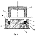
- a press device is used for this, as shown for example in Fig. 4.
- This mold consists of a die sleeve 4, in which the die core 5 is used. In the annular gap between the die sleeve 4 and the mold core 5, the rings 11, 12, 13 are inserted. The pressing process is then carried out with the pressure stamp 3.
- a trapezoidal cross section around the sealing body 1 is to be given, the shaped surface 31, 41 both on the pressure stamp 3 as well as at the die core 5 at an angle ⁇ arranged.
- the slope is chosen so that the resulting Trapezoid the shorter trapezoidal side rests on the shaft. Both the sealing effect and the friction between Sealing body 1 and shaft is influenced favorably.
- the required Press pressure given by the medium pressure.
- the specific pressure should not be less than that Medium pressure.
- the sealing body 1 Depending on the thickness h of the sealing body 1 that is desired, a number of the felt washers 11, 12, 13 together in the mold inserted and pressed. Preferably, the pressed ones Sealing body 1 a height h, the width b of the washers 11, 12, 13 corresponds. Depending on the thickness of the fabric the sealing body 1 consists of a pressed washer 1 - (Fig. 2) or several disks 11, 12, 13 ( Figures 3 and 4).
- the sealing body 1 is inclined (Fig. 2) intersected to its ring axis of the sealing body 1, so that the annular sealing body 1 opened and over the shaft can be pushed.
- the cut 2 obliquely to the ring axis of the Sealing body 1 has the advantage that the Glasses achieved a good seal at the interface becomes.
- the shaft was made of stainless steel, ground and surface hardened.
- the packaging space of the device was increased to Examining sealing body 1 equipped.
- the medium pressure was in 4 steps from 2 bar to 8 bar, or in 7 levels varied from 2 bar to 15 bar.
- the temperature the sealing body 1 near the shaft was with a thermocouple continuously recorded.
Landscapes
- Engineering & Computer Science (AREA)
- General Engineering & Computer Science (AREA)
- Mechanical Engineering (AREA)
- Sealing Devices (AREA)
- Sealing Material Composition (AREA)
Description
- Fig. 1
- den Dichtkörper in der Draufsicht,
- Fig. 2
- den Dichtkörper im Schnitt gemäß Fig. 1,
- Fig. 3
- einen zusammengesetzten Dichtkörper,
- Fig. 4
- eine Preßeinrichtung zur Herstellung der Dichtkörper.
- Abdichtende Wirkung
- Abstoßende Wirkung gegenüber der Flüssigkeit, die durch den Dichtkörper zurückgehalten werden soll
- Reduzierung der Gleitreibung
- Höhere thermische Belastbarkeit
- Schutz gegenüber abrasiv wirkender Partikel.
2870 g/m^2
Dicke 8,5 mm
36,2 Gew.% Faseranteil
63,8 Gew.% PTFE-Partikel
getränkt mit Silikonöl
1510 g/m^2
Dicke 3,5 mm
37,5 Gew.% Faseranteil
62,5 Gew.% PTFE-Partikel
getränkt mit Silikonöl
(PolyTetraFluorEthylen)
700 g/m^2
Dicke 1,0 mm
59,0 Gew.% Faseranteil
41,0 Gew.% PTFE-Partikel
getränkt mit Silikonöl
(PolyphenylenSulfid/PolyTetraFluorEthylen)
510 g/m^2 Dicke 1,6 mm
22,1 Gew.% Faseranteil
77,9 Gew.% PTFE-Partikel
getränkt mit Silikonöl
| Wellendurchmesser | 60 mm |
| Stopfbuchseninnendurchmesser | 80 mm |
| Wellenumfangsgeschwindigkeit | einstellbar bis 4 m/s |
| durchgepumptes Medium | reines Wasser |
| Mediumdruck | einstellbar bis 15 bar |
| Art der Packung | Temperatur °C | Reibmoment Nm | Leckage ml/min |
| Handelsübliche Geflechtspackung aus Aramid PTFE-impr. | 60 - 65 | 1,0 - 1,25 | 2,6 - 3,8 |
| Erfindungsgemäße Filzring- Packung | |||
| 1. 100% PES | 41 - 52 | 0,25 - 0.5 | 1,6 - 3,0 |
| 2. 100% PA | 48 - 59 | 0,5 - 0,75 | 1,2 - 2,8 |
| 3. 100% PTFE | 49 - 53 | 0,5 | 1,0 - 2,7 |
| 4. PPS/PTFE | 43 - 44 | 0,5 | 2,5 - 2,8 |
- 1
- Dichtkörper
- 2
- Schrägschnitt
- 3
- Druckstempel
- 31
- Formfläche
- 4
- Preßformbuchse
- 41
- Formfläche
- 5
- Preßformkern
- 11
- Dichtscheiben
- 12
- Dichtscheiben
- 13
- Dichtscheiben
- h
- Höhe des Dichtkörpers
- a
- Dicke der Ringscheibe Winkel der Formfläche
- b
- Breite der Ringscheiben
Claims (21)
- Vorrichtung zum Abdichten bewegter Teile, wie beispielsweise einer Welle, bei welcher das bewegte Teil in einem zwischen einem Gehäuse und dem bewegten Teil gebildeten Ringspalt mit einem mit Wirkstoff getränkten Dichtkörper (1) umgeben und der Ringspalt mit einem Deckel verschlossen ist, mit welchem ein Preßdruck auf den Dichtkörper (1) ausgeübt wird und wobei der Dichtkörper aus einem Material besteht, das eine mit der abzudichtenden Welle in Kontakt kommende Fläche aufweist, dadurch gekennzeichnet, daß der Dichtkörper (1) wenigstens aus einer Ringscheibe (11, 12, 13) besteht, die aus kompressiblen Textil- oder offenporigen Schaumstoffbahnen ausgeschnitten ist, so daß die mit der abzudichtenden Welle in Kontakt kommende Fläche eine ebene und unstrukturiert ausgebildete Schnittfläche ist, so daß ein hoher, in der wenigstens einen Ringscheibe eingelagerter PTFE-Anteil zur Wirkung gebracht werden kann.
- Vorrichtung nach Anspruch 1, dadurch gekennzeichnet, daß der Dichtkörper einen Wirkstoffanteil von mindestens 35 % bezogen auf das Gewicht des fertigen Dichtkörpers (1) aufweist, wobei dieser Wirkstoff aus PTFE-Feststoffteilchen besteht.
- Vorrichtung nach einem der Ansprüche 1 oder 2, dadurch gekennzeichnet, daß die Schnittfläche Unebenheiten von maximal 0,1 mm aufweist.
- Vorrichtung nach einem oder mehreren der Ansprüche 1 bis 3, dadurch gekennzeichnet, daß der Porenanteil des Textil- oder Schaumstoffes bezogen auf das Gesamtvolumen wenigstens 50 % beträgt.
- Vorrichtung nach einem oder mehreren der Ansprüche 1 bis 4, dadurch gekennzeichnet, daß der Dichtkörper (1) aus Filz besteht.
- Vorrichtung nach Anspruch 5, dadurch gekennzeichnet, daß der Dichtkörper (1) aus einem Nadelfilz mit einem Flächengewicht von 400 g - 3000 g/qm besteht.
- Vorrichtung nach einem oder mehreren der Ansprüche 1 bis 4, dadurch gekennzeichnet, daß der Dichtkörper (1) aus einem Vliesstoff besteht.
- Vorrichtung nach einem oder mehreren der Ansprüche 1 bis 4, dadurch gekennzeichnet, daß der Dichtkörper (1) aus einem Maschenstoff besteht.
- Vorrichtung nach einem oder mehreren der Ansprüche 1 bis 4, dadurch gekennzeichnet, daß der Dichtkörper (1) aus einem offenzelligen Schaum besteht.
- Vorrichtung nach einem oder mehreren der Ansprüche 1 bis 9, dadurch gekennzeichnet, daß der Dichtkörper (1) mit einem Schmierstoff getränkt ist.
- Vorrichtung nach Anspruch 10, dadurch gekennzeichnet, daß der Dichtkörper (1) vorzugsweise mit Silikonöl getränkt ist.
- Vorrichtung nach einem oder mehreren der Ansprüche 1 bis 11, dadurch gekennzeichnet, daß der Dichtkörper (1) aus Ringscheiben (11, 12, 13) zusammengesetzt ist.
- Vorrichtung nach einem oder mehreren der Ansprüche 1 bis 12, dadurch gekennzeichnet, daß die Dicke (a) der Ringscheiben (11, 12, 13) etwa 1 mm bis 10 mm beträgt, aus denen die jeweils benötigte Stärke (h) des Dichtkörpers (1) zusammengestellt ist.
- Vorrichtung nach einem oder mehreren der Ansprüche 1 bis 13, dadurch gekennzeichnet, daß der Dichtkörper (1) einen trapezförmigen Querschnitt aufweist, wobei die kürzere Trapezseite an dem bewegten Teil anliegt.
- Vorrichtung nach einem oder mehreren der Ansprüche 1 bis 14, dadurch gekennzeichnet, daß daß der Dichtkörper (1) aus mehreren trapezförmigen Körpern zusammengesetzt ist.
- Vorrichtung nach einem oder mehreren der Ansprüche 1 bis 15, dadurch gekennzeichnet, daß die Breite (b) und die Höhe (h) des Querschnitts des Dichtkörpers (1) annähernd gleich sind.
- Vorrichtung nach einem oder mehreren der Ansprüche 1 bis 16, dadurch gekennzeichnet, daß der ringförmige Dichtkörper (1) zum Öffnen für den Einbau durchschnitten ist.
- Verfahren zur Herstellung von Dichtkörpern (1) zum Abdichten bewegter Teile, wie beispielsweise einer Welle, nach einem oder mehreren der Ansprüche 1 bis 17, dadurch gekennzeichnet, daß aus einer Textil- oder Schaumstoffbahn ringförmige Scheiben (11, 12, 13) ausgeschnitten werden, die mit einem als Dispersion aufbereiteten Wirkstoff getränkt und getrocknet werden, worauf die getrockneten Scheiben (11, 12, 13) zu dem gewünschten Dichtkörper (1) zusammengelegt und gepreßt werden.
- Verfahren nach Anspruch 18, dadurch gekennzeichnet, daß die Ringscheiben (11, 12, 13) vor dem Pressen des Dichtkörpers (1) mit Schmiermittel getränkt werden.
- Verfahren nach Anspruch 19, dadurch gekennzeichnet, daß die Ringscheiben (11, 12, 13) nach dem Tränken mit einem Schmierstoff einer Temperaturbehandlung unterzogen werden.
- Verfahren nach einem oder mehreren der Ansprüche 18 bis 20, dadurch gekennzeichnet, daß vor dem Ausschneiden der ringförmigen Scheiben (11, 12, 13) die Textil- oder Schaumstoffbahn mit einer PTFE-Dispersion getränkt und getrocknet wird.
Applications Claiming Priority (2)
| Application Number | Priority Date | Filing Date | Title |
|---|---|---|---|
| DE4423043A DE4423043C2 (de) | 1994-07-01 | 1994-07-01 | Stopfbuchspackung |
| DE4423043 | 1994-07-01 |
Publications (2)
| Publication Number | Publication Date |
|---|---|
| EP0695899A1 EP0695899A1 (de) | 1996-02-07 |
| EP0695899B1 true EP0695899B1 (de) | 2000-09-20 |
Family
ID=6521974
Family Applications (1)
| Application Number | Title | Priority Date | Filing Date |
|---|---|---|---|
| EP95110220A Expired - Lifetime EP0695899B1 (de) | 1994-07-01 | 1995-06-30 | Stopfbuchspackung |
Country Status (3)
| Country | Link |
|---|---|
| EP (1) | EP0695899B1 (de) |
| AT (1) | ATE196536T1 (de) |
| DE (2) | DE4423043C2 (de) |
Families Citing this family (8)
| Publication number | Priority date | Publication date | Assignee | Title |
|---|---|---|---|---|
| CA2241756A1 (en) * | 1996-03-13 | 1997-09-18 | W.L. Gore & Associates Gmbh | Gasket with corrosion inhibitor |
| DE10122094B4 (de) * | 2001-05-07 | 2006-04-27 | Carl Freudenberg Kg | Stopfbuchspackung aus einem Dichtelement und Verfahren zu seiner Herstellung |
| DE10148715B4 (de) * | 2001-10-02 | 2007-10-25 | Carl Freudenberg Kg | Radialwellendichtung und Verfahren zu ihrer Herstellung |
| DE10250264B4 (de) * | 2002-10-28 | 2005-07-28 | Carl Freudenberg Kg | Dichtungsmaterial für Stopfbuchspackungen |
| DE10315333B4 (de) * | 2003-04-03 | 2005-10-27 | Carl Freudenberg Kg | Dichtung |
| DE10319753A1 (de) * | 2003-04-30 | 2004-11-25 | Carl Freudenberg Kg | Dichtungsanordnung |
| DE102010006896A1 (de) * | 2010-02-05 | 2011-08-11 | Robert Bosch GmbH, 70469 | Dichtung |
| DE102013010554A1 (de) * | 2013-06-15 | 2014-12-18 | Volkswagen Aktiengesellschaft | Schichtstruktur auf Silikonbasis mit oleophob-hydrophober Oberfläche, ein Verfahren zur Darstellung einer solchen sowie eine elektrische Maschine mit einer solchen |
Family Cites Families (7)
| Publication number | Priority date | Publication date | Assignee | Title |
|---|---|---|---|---|
| DE7118400U (de) * | 1971-09-30 | Kempchen & Co Gmbh | Dichtung, insbesondere Dichtungsscheibe, Dichtungsring | |
| US954655A (en) * | 1909-07-27 | 1910-04-12 | Edgar W Snyder | Packing. |
| DE972532C (de) * | 1953-08-26 | 1959-08-06 | Frankfurter Asbestwerke Paul K | Stopfbuechsenpackung |
| GB796610A (en) * | 1954-09-24 | 1958-06-18 | Du Pont | Improvements in or relating to sealing materials for use as gaskets, packings, and similar sealing devices |
| US3878031A (en) * | 1973-10-12 | 1975-04-15 | Frederic J Dormer | Packing for movable machine parts |
| DE3133271A1 (de) * | 1981-08-22 | 1983-03-03 | Irbit Holding AG, 1701 Fribourg | Zu einer rolle aufgewickelter schaumstoff-streifen, vorzugsweise zu abdichtungszwecken |
| DE4228073A1 (de) * | 1992-08-24 | 1994-03-03 | Merkel Martin Gmbh Co Kg | Dichtelement aus expandiertem Graphit |
-
1994
- 1994-07-01 DE DE4423043A patent/DE4423043C2/de not_active Expired - Fee Related
-
1995
- 1995-06-30 EP EP95110220A patent/EP0695899B1/de not_active Expired - Lifetime
- 1995-06-30 DE DE59508728T patent/DE59508728D1/de not_active Expired - Fee Related
- 1995-06-30 AT AT95110220T patent/ATE196536T1/de not_active IP Right Cessation
Also Published As
| Publication number | Publication date |
|---|---|
| DE4423043A1 (de) | 1996-01-11 |
| DE59508728D1 (de) | 2000-10-26 |
| DE4423043C2 (de) | 2000-09-07 |
| ATE196536T1 (de) | 2000-10-15 |
| EP0695899A1 (de) | 1996-02-07 |
Similar Documents
| Publication | Publication Date | Title |
|---|---|---|
| DE69511380T2 (de) | Verbundfaden zur herstellung geflochtener dichtung und verfahren zur herstellung des genannten verbundfadens | |
| DE2444847C2 (de) | Packung zum Abdichten beweglicher Maschinenteile | |
| DE69720680T2 (de) | Abdichtungssystem | |
| DE69515938T2 (de) | Reibbelagmaterialien | |
| EP1670872A1 (de) | FLACHDICHTUNGSWERKSTOFF IN FORM EINER VERSTäRKTEN VERBUNDFOLLIE (COMPOSITE FILM) | |
| DE2745356C2 (de) | Dichtelement | |
| DE2811528A1 (de) | Kolben und kolbenring fuer kolbenmaschinen, insbesondere brennkraftmaschinen | |
| DE69119266T2 (de) | Stopfbüchsenpackung und Verfahren zu ihrer Herstellung | |
| DE4423043C2 (de) | Stopfbuchspackung | |
| DE3009810A1 (de) | Dichtung | |
| DE1475768B2 (de) | Dichtung aus einer imprägnierten Glasfaserstruktur | |
| EP1432938B1 (de) | Radialwellendichtung und verfahren zu ihrer herstellung | |
| DE68909980T2 (de) | Flexibler Dichtungsring aus Grafit mit einer Aktivkohlenphase auf der Dichtfläche. | |
| DE10122094B4 (de) | Stopfbuchspackung aus einem Dichtelement und Verfahren zu seiner Herstellung | |
| WO1991019120A1 (de) | Dichtungsanordnung | |
| EP1081277B1 (de) | Maschine zur Herstellung und/oder Behandlung einer Materialbahn | |
| DE4323470C2 (de) | Dichtungsanordnung für die Abdichtung einer Wellendurchführung an der Schottwand eines Schiffes | |
| DE2914173C2 (de) | Imprägnierte Zylinderkopfdichtung und ihr Herstellungsverfahren | |
| EP1473493B1 (de) | Dichtungsanordnung | |
| DE10349414B4 (de) | Verfahren zur Herstellung von Formkörpern aus vliesstoffverstärktem PTFE | |
| DE1813249A1 (de) | Dichtungsmaterial | |
| DE2444502A1 (de) | Dichtung | |
| EP1586839A2 (de) | Dichtungsanordnung, insbesondere für eine Trockenanordnung | |
| DE10250264B4 (de) | Dichtungsmaterial für Stopfbuchspackungen | |
| DE2339353C3 (de) | Wellendichtring mit Rückförderelementen |
Legal Events
| Date | Code | Title | Description |
|---|---|---|---|
| PUAI | Public reference made under article 153(3) epc to a published international application that has entered the european phase |
Free format text: ORIGINAL CODE: 0009012 |
|
| AK | Designated contracting states |
Kind code of ref document: A1 Designated state(s): AT BE CH DE FR GB IT LI NL SE |
|
| 17P | Request for examination filed |
Effective date: 19960726 |
|
| 17Q | First examination report despatched |
Effective date: 19980910 |
|
| GRAG | Despatch of communication of intention to grant |
Free format text: ORIGINAL CODE: EPIDOS AGRA |
|
| GRAG | Despatch of communication of intention to grant |
Free format text: ORIGINAL CODE: EPIDOS AGRA |
|
| GRAH | Despatch of communication of intention to grant a patent |
Free format text: ORIGINAL CODE: EPIDOS IGRA |
|
| RAP1 | Party data changed (applicant data changed or rights of an application transferred) |
Owner name: DEUTSCHE INSTITUTE FUER TEXTIL- UND FASERFORSCHUNG |
|
| GRAH | Despatch of communication of intention to grant a patent |
Free format text: ORIGINAL CODE: EPIDOS IGRA |
|
| GRAA | (expected) grant |
Free format text: ORIGINAL CODE: 0009210 |
|
| AK | Designated contracting states |
Kind code of ref document: B1 Designated state(s): AT BE CH DE FR GB IT LI NL SE |
|
| REF | Corresponds to: |
Ref document number: 196536 Country of ref document: AT Date of ref document: 20001015 Kind code of ref document: T |
|
| REG | Reference to a national code |
Ref country code: CH Ref legal event code: EP |
|
| REF | Corresponds to: |
Ref document number: 59508728 Country of ref document: DE Date of ref document: 20001026 |
|
| ITF | It: translation for a ep patent filed | ||
| REG | Reference to a national code |
Ref country code: CH Ref legal event code: NV Representative=s name: SPIERENBURG HELMLE-KOLB & PARTNER AG PATENT- UND M |
|
| ET | Fr: translation filed | ||
| GBT | Gb: translation of ep patent filed (gb section 77(6)(a)/1977) |
Effective date: 20010118 |
|
| PLBE | No opposition filed within time limit |
Free format text: ORIGINAL CODE: 0009261 |
|
| STAA | Information on the status of an ep patent application or granted ep patent |
Free format text: STATUS: NO OPPOSITION FILED WITHIN TIME LIMIT |
|
| 26N | No opposition filed | ||
| REG | Reference to a national code |
Ref country code: GB Ref legal event code: IF02 |
|
| PGFP | Annual fee paid to national office [announced via postgrant information from national office to epo] |
Ref country code: GB Payment date: 20030602 Year of fee payment: 9 |
|
| PGFP | Annual fee paid to national office [announced via postgrant information from national office to epo] |
Ref country code: FR Payment date: 20030618 Year of fee payment: 9 |
|
| PGFP | Annual fee paid to national office [announced via postgrant information from national office to epo] |
Ref country code: SE Payment date: 20030620 Year of fee payment: 9 |
|
| PGFP | Annual fee paid to national office [announced via postgrant information from national office to epo] |
Ref country code: BE Payment date: 20030623 Year of fee payment: 9 Ref country code: AT Payment date: 20030623 Year of fee payment: 9 |
|
| PGFP | Annual fee paid to national office [announced via postgrant information from national office to epo] |
Ref country code: NL Payment date: 20030624 Year of fee payment: 9 |
|
| PGFP | Annual fee paid to national office [announced via postgrant information from national office to epo] |
Ref country code: DE Payment date: 20030625 Year of fee payment: 9 |
|
| PGFP | Annual fee paid to national office [announced via postgrant information from national office to epo] |
Ref country code: CH Payment date: 20030701 Year of fee payment: 9 |
|
| PG25 | Lapsed in a contracting state [announced via postgrant information from national office to epo] |
Ref country code: LI Free format text: LAPSE BECAUSE OF NON-PAYMENT OF DUE FEES Effective date: 20040630 Ref country code: GB Free format text: LAPSE BECAUSE OF NON-PAYMENT OF DUE FEES Effective date: 20040630 Ref country code: CH Free format text: LAPSE BECAUSE OF NON-PAYMENT OF DUE FEES Effective date: 20040630 Ref country code: BE Free format text: LAPSE BECAUSE OF NON-PAYMENT OF DUE FEES Effective date: 20040630 Ref country code: AT Free format text: LAPSE BECAUSE OF NON-PAYMENT OF DUE FEES Effective date: 20040630 |
|
| PG25 | Lapsed in a contracting state [announced via postgrant information from national office to epo] |
Ref country code: SE Free format text: LAPSE BECAUSE OF NON-PAYMENT OF DUE FEES Effective date: 20040701 |
|
| BERE | Be: lapsed |
Owner name: DEUTSCHE *INSTITUTE FUR TEXTIL- UND FASERFORSCHUNG Effective date: 20040630 |
|
| PG25 | Lapsed in a contracting state [announced via postgrant information from national office to epo] |
Ref country code: NL Free format text: LAPSE BECAUSE OF NON-PAYMENT OF DUE FEES Effective date: 20050101 Ref country code: DE Free format text: LAPSE BECAUSE OF NON-PAYMENT OF DUE FEES Effective date: 20050101 |
|
| REG | Reference to a national code |
Ref country code: CH Ref legal event code: PL |
|
| GBPC | Gb: european patent ceased through non-payment of renewal fee |
Effective date: 20040630 |
|
| PG25 | Lapsed in a contracting state [announced via postgrant information from national office to epo] |
Ref country code: FR Free format text: LAPSE BECAUSE OF NON-PAYMENT OF DUE FEES Effective date: 20050228 |
|
| EUG | Se: european patent has lapsed | ||
| NLV4 | Nl: lapsed or anulled due to non-payment of the annual fee |
Effective date: 20050101 |
|
| REG | Reference to a national code |
Ref country code: FR Ref legal event code: ST |
|
| PG25 | Lapsed in a contracting state [announced via postgrant information from national office to epo] |
Ref country code: IT Free format text: LAPSE BECAUSE OF NON-PAYMENT OF DUE FEES Effective date: 20050630 |