EP0695337B1 - Verfahren zum entwachsen von schmieröl unter anwendung eines verfahrens, wobei kaltes lösungsmittel in kreislauf geführt wird - Google Patents
Verfahren zum entwachsen von schmieröl unter anwendung eines verfahrens, wobei kaltes lösungsmittel in kreislauf geführt wird Download PDFInfo
- Publication number
- EP0695337B1 EP0695337B1 EP94914884A EP94914884A EP0695337B1 EP 0695337 B1 EP0695337 B1 EP 0695337B1 EP 94914884 A EP94914884 A EP 94914884A EP 94914884 A EP94914884 A EP 94914884A EP 0695337 B1 EP0695337 B1 EP 0695337B1
- Authority
- EP
- European Patent Office
- Prior art keywords
- solvent
- oil
- wax
- feed
- membrane
- Prior art date
- Legal status (The legal status is an assumption and is not a legal conclusion. Google has not performed a legal analysis and makes no representation as to the accuracy of the status listed.)
- Expired - Lifetime
Links
- 239000002904 solvent Substances 0.000 title claims abstract description 389
- 238000000034 method Methods 0.000 title claims abstract description 75
- 230000008569 process Effects 0.000 title claims abstract description 73
- 239000010687 lubricating oil Substances 0.000 title claims description 35
- 239000012528 membrane Substances 0.000 claims abstract description 116
- 239000000706 filtrate Substances 0.000 claims abstract description 84
- 239000000203 mixture Substances 0.000 claims abstract description 53
- 239000012466 permeate Substances 0.000 claims abstract description 42
- 238000001914 filtration Methods 0.000 claims abstract description 28
- 239000002244 precipitate Substances 0.000 claims abstract description 5
- 239000003921 oil Substances 0.000 claims description 276
- YXFVVABEGXRONW-UHFFFAOYSA-N Toluene Chemical compound CC1=CC=CC=C1 YXFVVABEGXRONW-UHFFFAOYSA-N 0.000 claims description 36
- ZWEHNKRNPOVVGH-UHFFFAOYSA-N 2-Butanone Chemical compound CCC(C)=O ZWEHNKRNPOVVGH-UHFFFAOYSA-N 0.000 claims description 28
- 239000013078 crystal Substances 0.000 claims description 18
- 239000012465 retentate Substances 0.000 claims description 18
- 230000007935 neutral effect Effects 0.000 claims description 16
- 238000009835 boiling Methods 0.000 claims description 14
- 238000010790 dilution Methods 0.000 claims description 14
- 239000012895 dilution Substances 0.000 claims description 14
- 238000001816 cooling Methods 0.000 claims description 12
- 239000000047 product Substances 0.000 claims description 12
- 238000012546 transfer Methods 0.000 claims description 4
- 238000007865 diluting Methods 0.000 claims description 3
- 238000004064 recycling Methods 0.000 claims description 3
- 150000002576 ketones Chemical class 0.000 claims description 2
- 230000001376 precipitating effect Effects 0.000 claims 1
- 239000003507 refrigerant Substances 0.000 abstract description 8
- 239000003208 petroleum Substances 0.000 abstract description 5
- 230000001050 lubricating effect Effects 0.000 abstract description 4
- 238000011084 recovery Methods 0.000 description 29
- 238000004821 distillation Methods 0.000 description 16
- 238000005057 refrigeration Methods 0.000 description 16
- ATUOYWHBWRKTHZ-UHFFFAOYSA-N Propane Chemical compound CCC ATUOYWHBWRKTHZ-UHFFFAOYSA-N 0.000 description 12
- 230000009467 reduction Effects 0.000 description 11
- 238000000926 separation method Methods 0.000 description 11
- 150000001491 aromatic compounds Chemical class 0.000 description 7
- 239000001294 propane Substances 0.000 description 6
- 239000000243 solution Substances 0.000 description 6
- 238000007792 addition Methods 0.000 description 5
- 238000002425 crystallisation Methods 0.000 description 5
- 230000008025 crystallization Effects 0.000 description 5
- 239000004744 fabric Substances 0.000 description 5
- 239000007788 liquid Substances 0.000 description 5
- 239000002002 slurry Substances 0.000 description 5
- 239000011877 solvent mixture Substances 0.000 description 5
- -1 aliphatic ketones Chemical class 0.000 description 4
- HYBBIBNJHNGZAN-UHFFFAOYSA-N furfural Chemical compound O=CC1=CC=CO1 HYBBIBNJHNGZAN-UHFFFAOYSA-N 0.000 description 4
- 238000002347 injection Methods 0.000 description 4
- 239000007924 injection Substances 0.000 description 4
- 230000008016 vaporization Effects 0.000 description 4
- CSCPPACGZOOCGX-UHFFFAOYSA-N Acetone Chemical compound CC(C)=O CSCPPACGZOOCGX-UHFFFAOYSA-N 0.000 description 3
- UHOVQNZJYSORNB-UHFFFAOYSA-N Benzene Chemical compound C1=CC=CC=C1 UHOVQNZJYSORNB-UHFFFAOYSA-N 0.000 description 3
- 239000004215 Carbon black (E152) Substances 0.000 description 3
- ISWSIDIOOBJBQZ-UHFFFAOYSA-N Phenol Chemical compound OC1=CC=CC=C1 ISWSIDIOOBJBQZ-UHFFFAOYSA-N 0.000 description 3
- 239000004642 Polyimide Substances 0.000 description 3
- 230000008901 benefit Effects 0.000 description 3
- 230000001419 dependent effect Effects 0.000 description 3
- 238000010438 heat treatment Methods 0.000 description 3
- 229930195733 hydrocarbon Natural products 0.000 description 3
- 150000002430 hydrocarbons Chemical class 0.000 description 3
- 229920001721 polyimide Polymers 0.000 description 3
- 238000001556 precipitation Methods 0.000 description 3
- 238000012545 processing Methods 0.000 description 3
- 238000000638 solvent extraction Methods 0.000 description 3
- QQZOPKMRPOGIEB-UHFFFAOYSA-N 2-Oxohexane Chemical compound CCCCC(C)=O QQZOPKMRPOGIEB-UHFFFAOYSA-N 0.000 description 2
- SYBYTAAJFKOIEJ-UHFFFAOYSA-N 3-Methylbutan-2-one Chemical compound CC(C)C(C)=O SYBYTAAJFKOIEJ-UHFFFAOYSA-N 0.000 description 2
- QGZKDVFQNNGYKY-UHFFFAOYSA-N Ammonia Chemical compound N QGZKDVFQNNGYKY-UHFFFAOYSA-N 0.000 description 2
- 239000013466 adhesive and sealant Substances 0.000 description 2
- 239000003849 aromatic solvent Substances 0.000 description 2
- 238000010276 construction Methods 0.000 description 2
- 239000003085 diluting agent Substances 0.000 description 2
- 238000000605 extraction Methods 0.000 description 2
- 239000012510 hollow fiber Substances 0.000 description 2
- 239000000463 material Substances 0.000 description 2
- 239000002184 metal Substances 0.000 description 2
- 229940032007 methylethyl ketone Drugs 0.000 description 2
- 239000003607 modifier Substances 0.000 description 2
- XNLICIUVMPYHGG-UHFFFAOYSA-N pentan-2-one Chemical compound CCCC(C)=O XNLICIUVMPYHGG-UHFFFAOYSA-N 0.000 description 2
- FDPIMTJIUBPUKL-UHFFFAOYSA-N pentan-3-one Chemical compound CCC(=O)CC FDPIMTJIUBPUKL-UHFFFAOYSA-N 0.000 description 2
- 125000006850 spacer group Chemical group 0.000 description 2
- 238000005406 washing Methods 0.000 description 2
- NTIZESTWPVYFNL-UHFFFAOYSA-N Methyl isobutyl ketone Chemical compound CC(C)CC(C)=O NTIZESTWPVYFNL-UHFFFAOYSA-N 0.000 description 1
- UIHCLUNTQKBZGK-UHFFFAOYSA-N Methyl isobutyl ketone Natural products CCC(C)C(C)=O UIHCLUNTQKBZGK-UHFFFAOYSA-N 0.000 description 1
- CTQNGGLPUBDAKN-UHFFFAOYSA-N O-Xylene Chemical compound CC1=CC=CC=C1C CTQNGGLPUBDAKN-UHFFFAOYSA-N 0.000 description 1
- 239000004698 Polyethylene Substances 0.000 description 1
- 239000004743 Polypropylene Substances 0.000 description 1
- 239000004793 Polystyrene Substances 0.000 description 1
- 229910021529 ammonia Inorganic materials 0.000 description 1
- 125000003118 aryl group Chemical group 0.000 description 1
- 230000009286 beneficial effect Effects 0.000 description 1
- 230000015572 biosynthetic process Effects 0.000 description 1
- 239000001273 butane Substances 0.000 description 1
- 238000005266 casting Methods 0.000 description 1
- 229920002301 cellulose acetate Polymers 0.000 description 1
- 238000005119 centrifugation Methods 0.000 description 1
- 238000005345 coagulation Methods 0.000 description 1
- 230000015271 coagulation Effects 0.000 description 1
- 150000001875 compounds Chemical class 0.000 description 1
- 239000000470 constituent Substances 0.000 description 1
- 239000002826 coolant Substances 0.000 description 1
- 239000000498 cooling water Substances 0.000 description 1
- 238000010586 diagram Methods 0.000 description 1
- RXKJFZQQPQGTFL-UHFFFAOYSA-N dihydroxyacetone Chemical compound OCC(=O)CO RXKJFZQQPQGTFL-UHFFFAOYSA-N 0.000 description 1
- 238000001704 evaporation Methods 0.000 description 1
- 230000008020 evaporation Effects 0.000 description 1
- 239000012530 fluid Substances 0.000 description 1
- 238000009434 installation Methods 0.000 description 1
- 239000000314 lubricant Substances 0.000 description 1
- 238000004519 manufacturing process Methods 0.000 description 1
- 238000002156 mixing Methods 0.000 description 1
- 238000012986 modification Methods 0.000 description 1
- 230000004048 modification Effects 0.000 description 1
- IJDNQMDRQITEOD-UHFFFAOYSA-N n-butane Chemical compound CCCC IJDNQMDRQITEOD-UHFFFAOYSA-N 0.000 description 1
- OFBQJSOFQDEBGM-UHFFFAOYSA-N n-pentane Natural products CCCCC OFBQJSOFQDEBGM-UHFFFAOYSA-N 0.000 description 1
- 239000002667 nucleating agent Substances 0.000 description 1
- 230000035699 permeability Effects 0.000 description 1
- 229920000548 poly(silane) polymer Polymers 0.000 description 1
- 125000005575 polycyclic aromatic hydrocarbon group Chemical group 0.000 description 1
- 229920000573 polyethylene Polymers 0.000 description 1
- 229920000642 polymer Polymers 0.000 description 1
- 229920006254 polymer film Polymers 0.000 description 1
- 229920001155 polypropylene Polymers 0.000 description 1
- 229920002223 polystyrene Polymers 0.000 description 1
- 229920001343 polytetrafluoroethylene Polymers 0.000 description 1
- 239000004810 polytetrafluoroethylene Substances 0.000 description 1
- 230000002028 premature Effects 0.000 description 1
- 230000008707 rearrangement Effects 0.000 description 1
- 239000011369 resultant mixture Substances 0.000 description 1
- 230000035939 shock Effects 0.000 description 1
- 229920002379 silicone rubber Polymers 0.000 description 1
- 239000004945 silicone rubber Substances 0.000 description 1
- 239000007787 solid Substances 0.000 description 1
- 238000000935 solvent evaporation Methods 0.000 description 1
- 238000010998 test method Methods 0.000 description 1
- XLYOFNOQVPJJNP-UHFFFAOYSA-N water Substances O XLYOFNOQVPJJNP-UHFFFAOYSA-N 0.000 description 1
- 239000008096 xylene Substances 0.000 description 1
Images
Classifications
-
- C—CHEMISTRY; METALLURGY
- C10—PETROLEUM, GAS OR COKE INDUSTRIES; TECHNICAL GASES CONTAINING CARBON MONOXIDE; FUELS; LUBRICANTS; PEAT
- C10G—CRACKING HYDROCARBON OILS; PRODUCTION OF LIQUID HYDROCARBON MIXTURES, e.g. BY DESTRUCTIVE HYDROGENATION, OLIGOMERISATION, POLYMERISATION; RECOVERY OF HYDROCARBON OILS FROM OIL-SHALE, OIL-SAND, OR GASES; REFINING MIXTURES MAINLY CONSISTING OF HYDROCARBONS; REFORMING OF NAPHTHA; MINERAL WAXES
- C10G73/00—Recovery or refining of mineral waxes, e.g. montan wax
- C10G73/02—Recovery of petroleum waxes from hydrocarbon oils; Dewaxing of hydrocarbon oils
- C10G73/06—Recovery of petroleum waxes from hydrocarbon oils; Dewaxing of hydrocarbon oils with the use of solvents
Definitions
- the present invention is directed to a process for dewaxing waxy oil feeds, particularly waxy petroleum oil fractions.
- the present invention is specifically directed to a process for the solvent dewaxing of waxy petroleum oil feeds to obtain lubricating oil stocks which comprises contacting a cold oil/solvent filtrate stream from a solvent dewaxing process with a selective permeable membrane to selectively separate the cold oil/solvent filtrate into a cold solvent permeate stream and a cold filtrate stream.
- the cold solvent permeate stream is recycled to an oil/solvent/wax feed to the wax filtration step.
- the separated cold filtrate stream is contacted by indirect heat exchange with warm waxy oil feed to cool the warm waxy oil feed.
- cold solvent is typically added to a hot waxy raffinate to control crystallization of the wax in the feed. Chilling of the feed is accomplished by indirect heat exchange against cold filtrate from the dewaxing filters and with refrigerant. Solvent is usually recovered from the filtrate by a combination of heating, multi-stage flash, and distillation operations. The hot solvent so recovered is then chilled again to the desired temperature for recycling to the wax filter feed.
- a waxy oil feed is mixed with solvent from a solvent recovery system.
- the waxy oil feed/solvent mixture is cooled by indirect heat exchange in a scraped-surface, double pipe heat exchanger against cold filtrate, which is a mixture of oil and solvent recovered from a filter used to separate wax from a wax containing stream.
- the cold filtrate is a mixture of oil and solvent.
- the cooled feed mix is injected with additional cold solvent from the solvent recovery system.
- the resultant mixture is further cooled against vaporizing propane, ammonia, or other refrigerant gas in a second scraped-surface double pipe exchanger.
- the chilled feed slurry is mixed with more chilled solvent from the solvent recovery system to obtain a filter feed.
- the amount of circulating solvent is typically limited by either the capacities of the solvent recovery sections or the capacity of the refrigeration system used to cool the recovered solvent to the desired injection temperatures. These limitations on the solvent availability can restrict the feed rate to the filter since the filter feed (high viscosity oil plus low viscosity solvent) must have a sufficiently low viscosity to achieve an acceptable filtration rate.
- dewaxing of waxy feed is performed by mixing the feed with a solvent to completely dissolve the waxy feed at a suitable elevated temperature.
- the mixture is gradually cooled to an appropriate temperature required for the precipitation of the wax and the wax is separated on a rotary filter drum.
- the dewaxed oil is obtained by evaporation of the solvent and is useful as a lubricating oil of low pour point.
- the dewaxing apparatus is expensive and complicated. In many instances the filtration proceeds slowly and represents a bottleneck in the process because of low filtration rates caused by the high viscosity of the oil/solvent/wax slurry feed to the filter.
- the high viscosity of the feed to the filter is due to a low supply of available solvent to be injected into the feed stream to the filter. In some cases, lack of sufficient solvent can result in poor wax crystallization and ultimately lower lube oil recovery.
- the solvent is conventionally separated from the dewaxed oil by the addition of heat, followed by a combination of multistage flash and distillation operations.
- the separated solvent vapors must then be cooled and condensed and further cooled to the dewaxing temperature prior to recycle to the process.
- the most limiting factors in the solvent dewaxing process are the cost and size of the filters, the cost, size, and operating expense of the distillation equipment needed to separate the solvent from the dewaxed oil, and the cooling apparatus and cooling capacity required to cool the warm solvent separated from the dewaxed oil.
- the filter capacity could be increased if there were available more solvent by simply further diluting the oil/solvent/wax mixture feed to the filter to lower the viscosity of the feed.
- the problems to be solved were to increase the amount of solvent available to the solvent dewaxing process without increasing the overall solvent inventory and without increasing the size and capacity of the oil/solvent recovery distillation system and the refrigeration capacity required to cool the warm solvent separated by distillation.
- An additional problem to be solved was to increase the filtration capacity of the process without providing additional filtration apparatus.
- the present invention is directed to a process for solvent dewaxing a waxy oil feed to obtain petroleum oil lubricating stock.
- the waxy oil feed is diluted with solvent at the feed temperature, then is sequentially indirectly contacted with cold filtrate and refrigerant which reduce the temperature of the oil to crystallize and precipitate the wax constituents of the oil and is then directly contacted with cold solvent to obtain an oil/solvent/wax mixture.
- the directly added cold solvent also serves to dilute the oil/solvent/wax mixture in order to maintain a sufficiently low viscosity of the mixture such that the mixture, when fed to a filter, is readily separated into a wax/solvent slurry and a cold dewaxed oil/solvent filtrate stream.
- the total amount of solvent added to the waxy oil feed i.e. the solvent/oil ratio used, and the temperature to which the waxy oil feed is cooled are determined by the boiling range of the feed, the wax content of the feed, and the desired pour point of the dewaxed lubricating oil.
- the process includes contacting the dewaxed oil/solvent filtrate stream with a selective permeable membrane to selectively separate the filtrate stream into a solvent permeate stream and a retentatestream which contains the dewaxed oil and the remaining solvent.
- the solvent permeate stream is recycled to the filter feed stream.
- the retentate stream is then indirectly contacted with the waxy oil feed to cool the waxy oil feed.
- the oil/solvent filtrate stream side of the membrane is maintained at a positive pressure relative to the solvent permeate stream side of the membrane.
- the recycle of the solvent permeate stream to the filter feed stream substantially increases the amount of solvent available to the dewaxing process and increases the filter feed rate.
- the warm waxy oil feed is cooled in a heat exchanger by indirect heat exchange with the cold retentate to crystallize and precipitate the wax in the oil feed to form an oil/solvent/wax mixture.
- the oil/solvent/wax mixture is further cooled in a heat exchanger by indirect heat exchange with a cold refrigerant.
- the cold oil/solvent/wax mixture is further diluted with cold recycled permeate solvent to adjust the viscosity of the mixture and the mixture is fed to a filter which filters and removes the precipitated wax from the cold oil/solvent/wax mixture.
- a cold wax/solvent slurry is recovered and a cold dewaxed oil/solvent filtrate stream is recovered.
- the wax/solvent slurry is treated to recover a wax cake which can be further treated and washed with solvent to remove residual oil from the wax cake.
- the oil can be separated and recovered from the solvent wash stream and the solvent can be recycled.
- the cold oil/solvent filtrate stream is fed, at the filtration temperature, to a selective permeable membrane.
- the membrane selectively separates the cold filtrate into a cold solvent permeate stream and a cold retentate stream which contains the dewaxed oil and the remaining solvent.
- the cold solvent permeate stream at the filtration temperature is recycled to the filter feed stream.
- the cold retentate stream is fed to a heat exchanger to indirectly contact and cool the warm waxy oil feed.
- the separation and recycle of cold solvent from the oil/solvent filtrate stream to the filter feed achieves a substantial reduction in the amount of solvent that must be separated from the oil/solvent filtrate stream in the oil/solvent separation operation.
- the cold oil/solvent retentate stream after the selective removal of the solvent through the permeable membrane is sent to an oil/solvent separation operation in which the remaining solvent is removed by distillation from the dewaxed oil, cooled and recycled to the dewaxing process and the dewaxed lubricating oil product is recovered.
- a substantial portion of the cold solvent in the filtrate stream is transferred through the selective membrane and recycled directly to the filter feed.
- the solvent transferred from the filtrate through the selective permeable membrane and recycled to the filter feed does not have to be either heated in the oil/solvent recovery distillation system to separate the solvent or have to be subsequently cooled prior to recycle to the dewaxing process. More solvent is available to be added to the filter feed since the distillation recovery and/or refrigeration bottlenecks are significantly reduced or eliminated.
- the amount of solvent which is made to selectively permeate through the membrane and recycled to the filter feed is limited only by the size and permeability of the membrane and the hydraulic capacity of the rotary filters.
- the internal solvent circulation rate can be substantially increased and can be larger than the flow rate of the solvent recovered from the oil/solvent distillation recovery operation that is recycled to the dewaxing process in a conventional dewaxing process.
- the reduction in the viscosity of the oil/solvent/wax feed to the filter leads to an increase in the maximum feed rate to the filters.
- the higher solvent/oil ratio also contributes to higher oil yields on the filters and greater filter feed rates for heavy stocks which are generally filter area limited.
- the selective removal of solvent from the dewaxed oil/solvent filtrate stream by the selective permeable membrane can significantly reduce the distillation capacity required and the cost of removing the remaining solvent in the filtrate stream and reduce the capacity required and cost of subsequently cooling the separated distilled solvent to the dewaxing temperature.
- a principal advantage of the use of the selective permeable membrane in accordance with the present invention is that it provides the selective separation of cold solvent from the cold oil/solvent filtrate stream and recycle of the separated solvent at the filtration temperature directly to the filter feed stream.
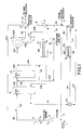
- the Figure is a schematic process flow diagram showing the solvent dewaxing process of the present invention including incremental cooling and incremental solvent addition to a warm waxy oil feed, filtration of wax, a selective permeable membrane for separating solvent from filtrate and recycle of solvent to the filter feed, and recycle of recovered solvent from an oil/solvent recovery operation.
- the feed to the process of the present invention can comprise any liquid hydrocarbon containing a dissolved or partially dissolved wax component from which it is desired to remove part or all of the wax component.
- the feed to the process of the present invention is typically petroleum lubricating oil raffinates obtained from extraction of distillates and/or deasphalting of vacuum tower distillates.
- the waxy oil feed to the process of the present invention is typically a waxy lubricating oil fraction which boils in the range of 304 to 704°C (580°F to 1300°F).
- the fraction boiling from about 304 to 454°C (580°F to 850°F) is generally referred to as light lubricating oil distillate.
- the fraction boiling from 427 to 566°C (about 800°F to about 1050°F) is generally referred to as heavy lubricating oil distillate.
- the fraction boiling from about 565 to 704°C (1050 to about 1300°F) is generally referred to as residual deasphalted oil.
- the distillate lubricating oils fed to the process of the present invention, prior to solvent dewaxing, are treated by solvent-extraction processes to remove aromatic and, if needed, asphaltenic compounds.
- the aromatic solvent extraction step can be carried out using a conventional phenol, furfural or n-methyl-pyrilidone solvent extraction procedure.
- Deasphalting processes use phenol and/or light hydrocarbon solvents, such as propane or butane.
- the waxy oil feed to the solvent dewaxing process of the present invention is, accordingly, relatively free of polycyclic aromatic hydrocarbons.
- the hydrocarbon feed is diluted with a first portion of solvent and then heated to a temperature to effectively dissolve all of the wax present in the feed.
- the warm feed is then indirectly cooled with cold water by conventional cooling means such as a tubular heat exchanger.
- the still warm waxy oil feed is then cooled by indirect heat exchange with cold retentate and with cold refrigerant and is further cooled and diluted by direct injection of recycle solvent from the recovery operation.
- the waxy oil feed is thus sequentially cooled and diluted to its desired wax filtration temperature, which temperature is selected to achieve a desired pour point for the dewaxed oil product.
- An oil/solvent/wax mixture is obtained and is further diluted with solvent to adjust the viscosity of the mixture and the mixture is fed to a filter which removes the wax from the oil/solvent/wax mixture.
- a cold wax cake is recovered and a cold oil/solvent filtrate stream is recovered.
- the cold oil/solvent filtrate is fed to a selective permeable membrane.
- the membrane selectively separates the cold filtrate into a solvent permeate stream and a cold retentate stream which contains the dewaxed oil and the remaining solvent.
- the cold solvent permeate stream at the filtration temperature is recycled to the filter feed stream.
- the cold retentatestream is then contacted with the warm waxy oil feed by indirect heat exchange.
- the retentate is sent to an oil/solvent separation operation in which the remaining solvent is removed from the dewaxed oil and recycled to the dewaxing process and the wax free lubricating oil stock product is recovered.
- Typical distillate feeds to the process of this invention are: Approximate Boiling Range, °C (°F) Light Neutral Lubricating Oil Feed Stock 304-454°C (580-850°F) Heavy Neutral Lubricating Oil Feed Stock 454-566°C (850-1050°F) Deasphalted Lubricating Oil Feed Stock 565-704°C (1050-1300°F)
- cloud point as used herein is intended to mean the temperature at which wax crystallization begins to occur, and the term pour point is the minimum temperature at which the oil will first move in a standard tube after quickly turning the tube on its side following a standard chilling procedure as set forth in ASTM test method D-97.
- the dewaxing solvents used in the present invention can be an aliphatic ketone, such as acetone, methyl ethyl-ketone, diethyl ketone, methyl n-propyl ketone, methyl isopropyl ketone, methyl-n-butyl ketone, methyl isobutyl ketone or other lower aliphatic ketones and mixtures thereof.
- the solvent also can include an aromatic solvent such as benzene, toluene, xylene and the like.
- the preferred solvent is a mixture of methyl ethyl ketone and toluene.
- the dewaxing solvent used in the present invention performs several important functions.
- the solvent dilutes the waxy oil feed and dissolves the oil component, cools the oil feed to the dewaxing temperature and lowers the solubility of the wax in the oil, forms a wax precipitate having a crystalline structure that facilitates separation of the wax from the oil and solvent in a filtration step and maintains a desired low viscosity to facilitate handling and processing of the oil/solvent/wax mixture through the heat exchangers and filters used in the process.
- the process of the present invention employs a mixture of MEK and toluene solvents.
- the MEK has poor solvent power for wax and relatively good solvency for oil.
- the toluene is included to increase oil solubility at dewaxing temperatures and to reduce oil/solvent solution viscosity to improve its filterability.
- solvents with high ketone content is beneficial because it increases filter rates by virtue of its lower viscosity and it reduces the dewaxing temperature differential between filtration temperature and pour point of dewaxed oil due to its lower wax solution power relative to toluene.
- the volume percent ratio of MEK/toluene can be 25:75 to 100:0, preferably 40:60 to 80:20 and typically about 65:35.
- the preferred ratios depend on the waxy oil raffinate feed to be dewaxed.
- the ratio of MEK/toluene can be 65:35 to 95:5; for dewaxing heavy neutral lube oil feed stock the ratio of MEK/toluene can be 50:50 to 75:25, and for dewaxing deasphalted lube oil feed stock the ratio of MEK/toluene can be 40:60 to 70:30.
- the solvent is added to the waxy oil feed sequentially at a number of injection points in the chilling train.
- the manner of solvent addition affects crystal size and subsequent filtration rates. Large, well defined crystals result in high filter rates and good washing efficiency with a corresponding high dewaxed oil yield and a low oil content wax product. Small or ill-defined crystals form a cake with resultant poor filtration characteristics which lead to lower dewaxed oil yields, poor wax quality and reduced oil production rates.
- All solvent additions made at or below wax crystallization temperature should be made at about the same temperature as the oil/solvent/wax to which it is added to avoid shock chilling which promotes formation of fine, difficult to filter crystals.
- the solvent is added step-wise during the process in order to maintain the viscosity of the oil/solvent/wax mixture at a desirable low level to facilitate handling and processing of the mixture through the scraped surface double pipe heat exchangers and the filtration of the wax in the filter apparatus.
- total solvent dilution to oil feed ratio will depend to a large extent on the wax content of the feed, the viscosity of the feed and the desired pour point of the dewaxed oil product.
- total solvent to oil dilution ratio as used herein is intended to mean the total volume of the solvent that is added to the initial volume of the oil feed during the dewaxing process.
- the total solvent to oil ratio can, accordingly, be 6:1 to 1:1, typically 4:1 to 3:1, depending on the nature and viscosity of the waxy oil feed.
- the dewaxing temperature is the temperature at which the oil/solvent/wax mixture is fed to the rotary filter drum and depends primarily on the desired pour point of the dewaxed oil product. Typical dewaxing temperatures for light neutral lubricating stocks are -23°C to -18°C, and for heavy neutral stocks are -18°C to -7°C.
- the filterability of oil/solvent/wax mixtures is dependent to a great extent on the size and shape of the wax crystals. Crystal growth can be affected by use of low chilling rates and high solvent concentrations.
- Dewaxing aids or wax crystal modifiers have been found effective in dewaxing of certain heavy lube oil stocks. These can be either nucleating agents that initiate crystal growth or growth modifiers that affect crystal growth. The crystals that are obtained are compact and are more readily separated from the oil.
- the conventional dewaxing aids can be used in the present process.
- a membrane module comprised of either hollow fibers or spiral wound or flat sheets is used to selectively remove cold solvent from the filtrate for recycle to the filter feed.
- the selective separation of the solvent and the recycle of the permeate solvent to the filter feed are both carried out at the filter temperature or at about the filter temperature.
- the optimum level of solvent removal is a function of filter feed properties and unit specific operating constraints.
- the present invention allows a significant increase in waxy oil feed rate to a dewaxing plant by debottlenecking the filtration, refrigeration and oil recovery sections of the plant.
- a preferred membrane module is described as follows:
- the membrane materials that can be used include, but are not limited to isotropic or anisotropic materials constructed from polyethylene, polypropylene, cellulose acetate, polystyrene, silicone rubber, polytetrafluoroethylene, polyimides, or polysilanes.
- Asymmetric membranes may be prepared by casting a polymer film solution onto a porous polymer backing, followed by solvent evaporation to provide a permselective skin and coagulation/ washing.
- a suitable polyimide, based on 5(6)-amino-1-(4'-aminophenyl)-1,3-trimethylindane, is commercially available as "Matrimid 5218".
- the membrane can be configured as either a flat sheet (plate and frame), hollow fiber, or spiral wound module.
- a spiral wound module is preferred due to its balance between high surface area and resistance to fouling.
- Typical construction of such a module comprises layers of the selected membrane wound upon a perforated metal or solvent resistant tube.
- the membrane layers would be separated by alternate layers of permeate and retentate spacers sized to provide an acceptable pressure drop from inlet to outlet of typically 14 - 70 kPa gauge (2-10 psig).
- Appropriate adhesives and sealants designed to maintain separate permeate and retentate flow channels and to minimize structural rearrangement upon use complete the construction.
- Modules of any size can be constructed, but typically are 254 mm (10 inches) in diameter and 1220 mm (48 inches) long having 18 - 27 m 2 (200-300 ft 2 ) surface area. Feed flow to each module varies according to application but is on the order of 30,240 - 38,000 1/day (8,000 - 10,000 gal/day); the corresponding permeate rate is on the order of 3800 - 7600 1/day (1,000 - 2,000 gal/day). Typical transmembrane pressure drop is about 2800 - 5600 kPa (400 - 600 psi). A commercial installation will vary in size with application and specific membrane performance but will typically employ on the order of 500-1500 modules for a world scale lube dewaxing plant.
- the chilled oil/solvent flows through the scraped-surface double pipe heat exchangers and is cooled by indirect heat exchange with cold filtrate.
- the wax crystallization begins in the first of two or more such heat exchangers.
- the cold surface of the heat exchanger is continually scraped to remove crystallized wax and to maintain the wax dispersed in the oil/solvent liquid.
- a second type of scraped-surface double pipe heat exchanger that can be used is one in which a vaporizing propane refrigerant is used to cool the waxy oil feed.
- the oil/solvent liquid is further cooled and additional wax crystallized in the later used heat exchangers.
- the surfaces of the heat exchanger are continually scraped to remove crystallized wax and to maintain the wax dispersed in the oil/solvent liquid.
- the wax can be separated from the cold oil/solvent/wax mixture by filtration or centrifugation.
- the cold oil/solvent/wax mixture flows from the double pipe heat exchangers to an injected dilution solvent step and then to a rotary drum vacuum filter in which a compartmentalized cloth covered drum rotates, partly submerged in enclosed filter cases in which the wax is separated from the oil/solvent liquid.
- a wax-free oil/solvent filtrate solution is drawn through the filter cloth to filtrate tanks in which a vacuum which induces filtration is maintained.
- a wax cake is deposited upon the drum filter cloth during filtration and is washed on the filter cloth continuously and automatically with cold solvent to produce a low oil content wax product.
- the wax cake is then removed from the filter cloth and recovered for further processing.
- the principal features of the dewaxing process of the present invention are the large amount of solvent that is transferred through the selective permeable membrane for recycle directly to the filter feed, the temperature of the cold oil/solvent filtrate from which the solvent is selectively removed and the total volume of dilution solvent to oil, i.e. total solvent/oil ratio available to carry out the dewaxing process.
- the amount of solvent that is transferred from the oil/solvent filtrate through the selective permeable membrane for recycle to the filter feed represents solvent that does not have to be recovered from the oil/solvent retentate by distillation and does not have to be subsequently cooled prior to recycle to the dewaxing process, thus resulting in substantial savings in solvent inventory, distillation capacity and refrigeration capacity.
- the solvent performs the functions of diluent, solvent for the oil, coolant and non-solvent for the wax.
- the solvent is added to the waxy oil feed at different points along the dewaxing process sequence.
- the total amount of solvent added is referred to herein as the total solvent/oil ratio and is based on the total volume of solvent added to the waxy oil feed during the dewaxing process.
- the total solvent to oil dilution ratio can be 6:1 to 1:1 and depends primarily on the type of waxy oil feed and the desired dewaxed oil pour point.
- the dewaxing temperature is dependent upon the desired pour point of the dewaxed oil and is typically a few degrees below the pour point, for example, 2.8 to 6°C (5 to 10°F) below the pour point.
- the pour point is also dependent on the type of oil feed.
- a waxy oil feed after removal of aromatic compounds by convention phenol or furfural extraction, is fed through line 1 at a temperature of 54 to 93°C (about 130 to 200°F) and is mixed with MEK/toluene solvent fed through line 2 at a temperature of 38 to 60°C (100 to 140°F) from the solvent recovery section, not shown.
- the solvent is added at a volume ratio of 0.5 to 3.0 solvent per part of waxy oil feed.
- the waxy/oil solvent mixture is fed to heat exchanger 3 and heated by indirect heat exchange to a temperature above the cloud point of the mixture of 60 to 99°C (about 140 to 210°F) to ensure that all wax crystals are dissolved and in true solution.
- the warm oil/solvent mixture is then fed through line 4 to heat exchanger 5 in which it is cooled to a temperature of about 38 to 82°C (100 to 180°F).
- the waxy oil feed in line 101 is then mixed directly with solvent at a temperature of 4 to 60°C (40 to 140°F) fed through line 102 to cool the feed to a temperature of 4 to 60°C (40 to 140°F), depending on the viscosity, grade and wax content of the waxy oil feed.
- the solvent is added to the waxy oil feed through line 102 in an amount of 0.5 to 2.0 parts by volume per part of waxy oil in the feed.
- the temperature and solvent content of the cooled waxy oil feed stream in line 101 are controlled at a few degrees above the cloud point of the oil feed/solvent mixture to preclude premature wax precipitation.
- a typical target temperature for the feed in line 101 would be 4 - 60°C (40 - 140°F).
- the cooled waxy oil feed and solvent are fed through line 101 to scraped-surface double pipe heat exchanger 9.
- the cooled waxy oil feed is further cooled by indirect heat exchange in heat exchanger 9 against cold filtrate fed to the heat exchanger 9 through line 109. It is in heat exchanger 9 that wax precipitation typically first occurs.
- the cooled waxy oil feed is withdrawn from exchanger 9 by line 103 and is injected directly with additional cold solvent feed through line 104.
- the cold solvent is injected through line 104 into line 103 in an amount of 0 to 1.5, e.g. 0.1 to 1.5, parts by volume based on one part of waxy oil feed.
- the waxy oil feed is then fed through line 103 to direct heat exchanger 10 and is further cooled against vaporizing propane in scraped-surface, double pipe heat exchanger 10 in which additional wax is crystallized from solution.
- the cooled waxy oil feed is then fed through line 105 and mixed with additional cold solvent injected directly through line 106.
- the cold solvent is fed through line 106 in an amount of 0.1 to 3.0, e.g. 0.5 to 1.5, parts by volume per part of waxy oil feed.
- the final injection of cold solvent at or near the filter feed temperature through line 106 serves to adjust the solids content of the oil/solvent/wax mixture feed to the filter 11 to 3 to 10 volume percent, in order to facilitate filtration and removal of the wax from the waxy oil/ solvent/wax mixture feed to the filter 11.
- the mixture is then fed through line 107 to the filter 11 and the wax is removed.
- the temperature at which the oil/solvent/wax mixture is fed to the filter is the dewaxing temperature and can be -23 to -7°C (-10 to +20°F) and determines the pour point of the dewaxed oil product.
- a slipstream 19 from line 104 can be combined with the solvent in line 106 to adjust the solvent temperature prior to injecting the solvent in line 106 into line 107.
- the remaining solvent in line 104 is injected into line 103 to adjust the solvent dilution and viscosity of the oil/solvent/wax mixture feed prior to feeding the mixture through line 103 to the exchanger 10.
- the oil/ solvent/wax mixture in line 107 is then fed to rotary vacuum drum filter 11 in which the wax is separated from the oil and solvent.
- One or more filters 11 can be used and they can be arranged in parallel or in a parallel/series combination.
- a separated wax is removed from the filter through line 112 and is fed to indirect heat exchanger 13 to cool solvent recycled from the solvent recovery operation.
- the cold filtrate is removed from filter 11 through line 108 and at this point contains a solvent to oil ratio of 15:1 to 2:1 parts by volume and is at a typical temperature of -23 to 10°C (-10 to +50°F).
- the cold filtrate in line 108 is increased in pressure by pump 11A and fed through line 108 to selective permeable membrane module M1 at the filtration temperature.
- the membrane module M1 contains a low pressure solvent permeate side 6 and a high pressure oil/solvent filtrate side 8 with the selective permeable membrane 7 in between.
- the cold oil/solvent filtrate at the filtration temperature is fed through line 108 to the membrane module M1.
- the membrane 7 allows the cold MEK/tol solvent from the oil/solvent filtrate side 8 to selectively permeate through the membrane 7 into the low pressure permeate side 6 of the membrane module.
- the cold solvent permeate is recycled directly to the filter feed line 107 at the filter feed temperature.
- the solvent selectively permeates through the membrane 7 in an amount of 0.1 to 3.0 parts by volume per part of waxy oil in the feed.
- the filtrate side of the membrane is maintained at a positive pressure of about 1400 - 7000 kPa gauge (200 - 1000 psig) and preferably 400 - 800 psig greater than the pressure of the solvent permeate side of the membrane to facilitate the transport of solvent from the oil/solvent filtrate side of the membrane to the solvent permeate side of the membrane.
- the solvent permeate side of the membrane is typically at 0 - 4200 kPa gauge (0 - 600 psig), preferably 70 - 700 kPa gauge (10 - 100 psig) and more preferably 70 - 350 kPa gauge (10 - 50 psig), for example at 175 kPa gauge (about 25 psig).
- the membrane 7 has a large surface area which allows very efficient selective solvent transfer through the membrane.
- the cold retentate removed from the membrane module M1 is fed through line 109 to indirect heat exchanger 9, in which it is used to indirectly cool warm waxy oil feed fed through line 101 to the heat exchanger 9.
- the amount of solvent to be removed by the membrane module M1 is determined, to some extent, by the feed pre-cooling requirements.
- the cold retentate is then fed through line 111 to line 115 and sent to an oil/solvent separation operation in which the remaining solvent is removed from the dewaxed oil.
- the solvent is separated from the oil/solvent retentate in the oil/solvent recovery operation, not shown, by heating and removing the solvent by distillation.
- the separated solvent is recovered and returned through line 2 to the dewaxing process.
- the wax and solvent free oil product is recovered and used as lubricating oil stock.
- a portion of the solvent from the solvent recovery operation is fed through line 2 at a temperature of 38 to 60°C (about 100 to 140°F) to be mixed with waxy oil feed fed through line 1.
- Another portion of the recovered solvent is fed through line 2 to line 16 and into heat exchangers 17 and 13 in which the solvent is cooled to about the dewaxing temperature by indirect heat exchange against cooling water and wax/solvent mixture, respectively.
- Another portion of the recovered solvent is fed through lines 2, 16 and 14 to heat exchanger 15 in which it is cooled by indirect heat exchange with cold refrigerant, e.g. vaporizing propane, to about the fluid temperature in line 103 and fed through line 104 and injected into the oil/solvent/wax mixture in line 103.
- cold refrigerant e.g. vaporizing propane
- the retentate stream in line 111 can be fed through valve 15a and line 114 to membrane module M2.
- the retentate is fed to module M2 at a temperature of 59 to 122°F (15 to 50°C) and solvent is selectively transferred through the membrane 7a and is fed through line 116 and recycled to the dewaxing process.
- the membrane module M2 is operated in the same manner as membrane module M1, except for the temperature of separation, and can contain the same membrane as module M1.
- the use of the membrane module M2 embodiment allows reducing cooling capacity requirements and reducing utility consumption in the solvent/oil recovery section.
- the recovered solvent permeate is at a higher temperature, i.e., 15 - 50°C (59 to 122°F)
- the solvent from the membrane module M2 must be cooled prior to being used in the dewaxing process, as for example in heat exchangers 15 or 17 and 13.
- the higher temperature allows more solvent to be recovered because of the higher permeate rate of the higher temperature as compared to M1.
- a MEK/tol. solvent is used at a ratio of MEK/tol. of 25:75 to 100:0, preferably 60:40 to 90:10, and more preferably 70:30 to 80:20.
- the total solvent to oil dilution ratio is 6:1 to 1:1, preferably 5:1 to 2:1, and more preferably 4:1 to 2:1.
- the dewaxing temperature i.e, the temperature at which the oil/solvent/wax mixture is fed to the filter, is -29 to 21°C (-20 to +70°F), preferably -23 to -1°C (-10 to +30°F), and more preferably -23 to -12°C (-10 to +10°F).
- the oil/solvent filtrate from the filter contains a ratio of solvent to oil of 6:1 to 1:1, preferably 5:1 to 3:1.
- the oil/solvent filtrate is fed to the membrane module M1 at the dewaxing temperature.
- the operating temperature of the selective membrane can be -29 to 21°C (-20 to +70°F), preferably -23 to -1°C (-10 to +30°F), and more preferably -23 to -12°C (-10 to +10°F).
- the oil/solvent filtrate side of the membrane is maintained at a positive pressure relative to the solvent permeate side of the membrane of 1400 to 7000 kPa gauge (200 to 1000 psig), preferably 2800 to 5600 kPa gauge (400 to 800 psig), and more preferably 3500 to 4900 kPa gauge (500 to 700 psig).
- the solvent permeate side of the membrane is typically maintained at a pressure of 70 to 350 kPa gauge (10 to 50 psig).
- a sufficient amount of solvent is transferred through the membrane to add 0.1 to 2.0 parts and preferably 0.5 to 1.5 parts of solvent per part of oil feed to the filter feed.
- a dewaxed oil is obtained having a pour point of -29 to 21°C (-20 to +70°F) preferably -12 to -1°C (-10 to 30°F), and more preferably -21 to -12°C (-5 to +10°F).
- a heavy neutral lubricating oil feed boiling in the range of 371 to 704°C (700°F to 1300°F), preferably 427 to 621°C (800 to 1150°F), and more preferably 454 to 566°C (850 to 1050°F) is treated to remove aromatic compounds and is pre-diluted with solvent, heated to melt wax crystals and cooled.
- a MEK/tol. solvent is used at a ratio of MEK/tol. of 25:75 to 100:0, preferably 50:50 to 70:30 and more preferably 55:45 to 65:35.
- the total solvent to oil dilution ratio is 6:1 to 1:1, preferably 4:1 to 2:1, and more preferably 4:1 to 3:1.
- the dewaxing temperature i.e, the temperature at which the oil/solvent/wax mixture is fed to the filter, is -29 to 21°C (-20 to +70°F), preferably -18 to 10°C (0 to 50°F), and more preferably -12 to -7°C (10 to 20°F).
- the oil/solvent filtrate from the filter contains a ratio of solvent to oil of 6:1 to 1:1, preferably 5:1 to 2:1 and more preferably 5:1 to 3:1.
- the oil/solvent filtrate is fed to the membrane module M1 at the dewaxing temperature.
- the operating temperature of the selective membrane can be -29 to 21°C (-20 to +70°F), preferably -18 to 10°C (0 to 50°F), and more preferably -12 to -7°C (10 to 20°F).
- the oil/solvent filtrate side of the membrane is maintained at a positive pressure relative to the solvent permeate side of the membrane of 1400 to 7000 kPa gauge (200 to 1000 psig), preferably 2800 to 5600 kPa gauge (400 to 800 psig), and more preferably 3500 to 4900 kPa gauge (500 to 700 psig).
- a sufficient amount of solvent is transferred through the membrane to add 0.1 to 3.0 parts, preferably 0.5 to 1.5 parts of solvent per part of oil feed to the filter feed.
- a dewaxed oil is obtained having a pour point of -23 to 21°C (-10 to +70°F), preferably -12 to 16°C (10 to 60°F), and more preferably -9 to -1°C (15 to 30°F).
- a deasphalted lubricating oil feed boiling in the range of 316 to 1371°C (600 to 2500°F), preferably 482 to 816°C (900 to 1500°F), and more preferably 566 to 704°C (1050 to 1300°F) is treated to remove aromatic compounds and is pre-diluted with solvent, heated to melt wax crystals and cooled.
- a MEK/tol. solvent is used at a ratio of MEK/tol. of 25:75 to 100:0, preferably 45:55 to 70:30 and more preferably 50:50 to 60:40.
- the total solvent to oil dilution ratio is 6:1 to 1:1, preferably 5:1 to 2:1, and more preferably 5:1 to 3:1.
- the dewaxing temperature i.e, the temperature at which the oil/solvent/wax mixture is fed to the filter, is -29 to 21°C (-20 to +70°F), preferably -18 to 10°C (0 to 50°F), and more preferably -12 to -1°C (10 to 30°F).
- the oil/solvent filtrate from the filter contains a ratio of solvent to oil of 6:1 to 1:1, preferably 5:1 to 2:1 and more preferably 5:1 to 3:1.
- the oil/solvent filtrate is fed to the membrane module M1 at the dewaxing temperature.
- the operating temperature of the selective membrane can be -29 to 21°C (-20 to +70°F), preferably -18 to 10°C (0 to 50°F), and more preferably -12 to -1°C (10 to 30°F).
- the oil/solvent filtrate side of the membrane is maintained at a positive pressure relative to the permeate solvent side of the membrane of 1400 to 7000 kPa gauge (200 to 1000 psig), preferably 2800 to 5600 kPa gauge (400 to 800 psig), and more preferably 3500 to 4900 kPa gauge (500 to 700 psig).
- a sufficient amount of solvent is transferred through the membrane to add 0.1 to 3.0 parts, preferably 0.5 to 1.5 parts of solvent per part of oil feed to the filter feed.
- a dewaxed oil is obtained having a pour point of -23 to 21°C (-10 to +70°F) preferably -12 to 16°C (10 to 60°F), and more preferably -7 to -1°C (20 to 30°F).
- the dewaxed oil can be used as lubricating oil stock.
- the present invention is illustrated by the following Examples.
- a light neutral lubricating oil feed boiling in the range of 343 to 449°C (650 to 840°F) is treated to remove undesirable aromatic compounds and is prediluted with solvent, is heated to melt wax crystals and is cooled.
- the waxy oil feed is then fed to the dewaxing process at a rate of 2.2 x 10 6 1 (14,000 barrels) a day based on oil feed.
- the solvent consists of a ratio of MEK/tol. of 70:30.
- the total solvent to oil dilution ratio is 4:1 based on volume.
- the dewaxing temperature i.e., the oil/solvent/wax mixture feed to the filter temperature is -21°C (-5°F).
- the filter removes the wax from the oil/solvent/wax mixture.
- a cold wax cake is recovered and a cold oil/solvent filtrate stream is recovered.
- the cold oil/solvent filtrate stream is fed to the membrane module M1.
- the membrane is incorporated in a spiral wound module having high surface area and low propensity for fouling.
- the module comprises layers of the membrane wound upon a perforated metal resistant tube.
- the membrane layers are separated by alternate layers of permeate and retenate spacers sized to provide an acceptable pressure drop from inlet to outlet of about 14 to 70 kPa gauge (2 to 10 psig).
- Adhesives and sealants are used to maintain separate permeate and retenate flow channels.
- the modules are constructed to be 254 mm (10 inches) in diameter and 1220 mm (48 inches) in length and to have a 18 to 27m 2 (200 to 300 ft 2 ) surface area. 500 modules are used.
- the solvent permeate feed rate for each module is 4,160 1/day (1,100 gal/day).
- the oil/solvent filtrate stream is fed to the membrane module at a rate of 8.0 x 10 6 1 (50,400 barrels) a day of solvent and 1.7 x 10 6 1 (10,500 barrels) a day of dewaxed oil.
- the oil/solvent filtrate stream side of the membrane is maintained at a positive pressure of 5600 kPa gauge (800 psig) and the solvent permeate side of the membrane is maintained at 1400 kPa gauge (about 200 psig).
- the process of the present invention results in substantial savings in distillation capacity to recover solvent from filtrate and in refrigeration capacity to cool the warmed separated solvent from the solvent/oil recovery operation to the necessary dewaxing temperature. In addition, there are considerable savings in solvent inventory requirements.
- the process of the present invention as compared to the prior art process to obtain the same level of dewaxing and pour point oil, achieves an about 40% reduction in the size and capacity of the oil/solvent recovery section and an about 50% reduction in the heat energy required to carry out solvent recovery as well as an about 45% reduction in the total refrigeration requirements.
- the total refrigeration requirements include the refrigeration required to cool the feed and crystallize wax from the feed, e.g., the refrigeration needed for the scraped-surface heat exchangers, as well as the refrigeration required to cool the warm distilled solvent from the solvent recovery operation to the dewaxing temperature.
- a heavy neutral lubricating oil feed boiling in the range of 454 to 565°C (850 to 1050°F) is treated to remove undesirable aromatic compounds and is prediluted with solvent, is heated to melt wax crystals and is cooled.
- the waxy oil feed is then fed to the dewaxing process at a rate of 1.75 x 10 6 1 (11,000 barrels) a day based on oil feed.
- the solvent consists of a ratio of MEK/tol. of 65:35.
- the total solvent to oil dilution ratio is 4:1 based on volume.
- the dewaxing temperature i.e. the feed to the filter temperature, is -12°C (+10°F).
- the filter removes the wax from the oil/solvent/wax mixture.
- a cold wax cake is recovered and a cold oil/solvent filtrate stream is recovered.
- the cold oil/solvent filtrate stream is fed to the membrane module M1.
- the membrane and module are the same as that of Example 1.
- the oil/solvent filtrate stream is fed to the membrane module at a rate of 7.3 x 10 6 1 (46,200 barrels) a day of solvent and 1.4 x 10 6 1 (8,800 barrels) a day of dewaxed oil.
- the oil/solvent filtrate stream side of the membrane is maintained at a positive pressure of 4900 kPa gauge (700 psig) and the solvent permeate side of the membrane is maintained at about 700 kPa (100 psig).
- the process of the present invention results in substantial savings in distillation capacity to recover solvent from filtrate and refrigeration capacity to cool the warmed separated solvent from the solvent/oil recovery operation to the necessary dewaxing temperature. In addition, there are considerable savings in solvent inventory requirements.
- the process of the present invention as compared to the prior art process to obtain the same level of dewaxing and pour point oil, achieves an about 40% reduction in the size and capacity of the oil/solvent recovery section and an about 45% reduction in the heat energy required to carry out solvent recovery as well as an about 40% reduction in the total refrigeration requirements.
- a deasphalted lubricating oil feed boiling in the range of 565 to 671°C (1050 to 1240°F) is treated to remove undesirable aromatic compounds and is prediluted with solvent, is heated to melt wax crystals and is cooled.
- the waxy oil feed is then fed to the membrane module at a rate of 1.6 x 10 6 (10,000 barrels) a day based on oil feed.
- the solvent consists of a ratio of MEK/tol. of 50:50.
- the total solvent to oil dilution ratio is 5.5:1 based on volume.
- the dewaxing temperature i.e. the feed to the filter temperature, is -11°C (15°F).
- the filter removes the wax from the oil/solvent/wax mixture.
- a cold wax cake is recovered and a cold oil/solvent filtrate stream is recovered.
- the cold oil/solvent filtrate stream is fed to the membrane module M1.
- the membrane and module are the same as that of Example 1.
- the oil/solvent filtrate stream is fed to the membrane module at a rate of 8.2 x 10 6 l (51,600 barrels) a day of solvent and 1.2 x 10 6 1 (7,800 barrels) a day of dewaxed oil.
- the oil/solvent filtrate stream side of the membrane is maintained at a positive pressure of 5600 kPa gauge (800 psig) and the solvent permeate side of the membrane is maintained at about 1400 kPa gauge (200 psig).
- the process of the present invention results in substantial savings in distillation capacity to recover solvent from filtrate and in refrigeration capacity to cool the warmed separated solvent from the solvent/oil recovery operation to the necessary dewaxing temperature. In addition, there are considerable savings in solvent inventory requirements.
- the process of the present invention as compared to the prior art process to obtain the same level of dewaxing and pour point oil, achieves an about 35% reduction in the size and capacity of the oil/solvent recovery section and an about 30% reduction in the heat energy required to carry out solvent recovery as well as an about 30% reduction in the total refrigeration requirements.
Landscapes
- Chemical & Material Sciences (AREA)
- Oil, Petroleum & Natural Gas (AREA)
- Engineering & Computer Science (AREA)
- Chemical Kinetics & Catalysis (AREA)
- General Chemical & Material Sciences (AREA)
- Organic Chemistry (AREA)
- Production Of Liquid Hydrocarbon Mixture For Refining Petroleum (AREA)
Claims (6)
- Verfahren zum Lösungsmittelentparaffinieren einer wachsartigen Ölbeschickung, welches umfaßt: Verdünnen des wachsartigen Ölbeschickungsstroms mit einem Lösungsmittel und Abkühlen des wachsartigen Ölbeschickungsstroms auf eine Temperatur von 4 bis 60°C und weiteres Abkühlen der wachsartigen Ölbeschickung durch indirekten Kontakt mit einem kalten Filtrat, danach aufeinanderfolgendes indirektes Abkühlen der wachsartigen Ölbeschickung in indirektem Wärmeaustauschern, damit die Wachskristalle kristallisieren und gefällt werden; aufeinanderfolgendes direktes Einsprühen von weiterem Lösungsmittel in den wachsartigen Ölbeschickungsstrom, um diesen weiter abzukühlen und zu verdünnen und die gewünschte Viskosität des wachsartigen Ölbeschickungsstroms zu erhalten, damit die Handhabung des wachsartigen Ölbeschickungsstroms innerhalb des Verfahrens erleichtert und das Filtern des kristallisierten Wachs aus dem wachsartigen Ölbeschickungsstrom vereinfacht wird und der gewünschte Pour-point des entparaffinierten Ölprodukts erhalten wird; und Kristallisieren und Fällen des Wachs aus der wachsartigen Ölbeschickung während des aufeinanderfolgenden Abkühlens der wachsartigen Ölbeschickung, wodurch eine Mischung von Öl/Lösungsmittel/Wachs mit einer Temperatur von -34 bis 21°C erhalten wird; Filtrieren der Mischung von Öl/Lösungsmittel/Wachs, um das Wachs zu entfernen und einen Öl/Lösungsmittel-Filtratstrom zu erhalten; Kontakt des Öl/Lösungsmittel-Filtratstroms mit einer Temperatur von -34 bis 21°C mit einer Seite einer selektiven semipermeablen Membran in einem Membranmodul, um das Lösungsmittel selektiv durch die Membran zu transportieren, damit auf der anderen Seite der Membran ein Lösungsmittelpermeat erhalten wird, wobei die Seite der Membran des Öl/Lösungsmittel-Filtratstroms im Verhältnis zum Druck auf der Lösungsmittelpermeatseite der Membran bei einem Überdruck gehalten wird; selektiver Transport von 20 bis 75 Vol.-% Lösungsmittel von der Filtratseite der Membran zur Lösungsmittelpermeatseite der Membran; Rezirkulieren des Lösungsmittelpermeats mit einer Temperatur von -34 bis 21°C zur Filterbeschickung; Abziehen eines Stroms des zurückgehaltenen Stoffs, der das restliche Lösungsmittel von der Filtratseite des Membranmoduls enthält; Kontakt des Stroms des zurückgehaltenen Stoffs durch indirekten Wärmeaustausch mit der warmen wachsartigen Ölbeschickung und Behandeln des abgezogenen Stroms des zurückgehaltenen Stoffs, um das restliche Lösungsmittel vom Öl abzutrennen; Gewinnen eines entparaffinierten Ölproduktstroms und eines Rohparaffinproduktstroms und Rezirkulieren des abgetrennten Lösungsmittels zum Verdünnungsschritt.
- Verfahren nach Anspruch 1, wobei das Verhältnis von Lösungsmittel:Öl im Öl/Lösungsmittel-Filtratstrom, bezogen auf das Volumen, 15:1 bis 3:1 beträgt.
- Verfahren nach Anspruch 1, wobei das Entparaffinierungslösungsmittel eine Mischung von Methylethylketon und Toluol in einem Volumenverhältnis von Keton:Toluol von 25:25 bis 100:0 umfaßt.
- Verfahren nach Anspruch 1, wobei die Membrantransporttemperatur -34 bis 21°C beträgt.
- Verfahren nach Anspruch 1, wobei das Verdünnungsverhältnis von gesamtem Lösungsmittel:Öl 6:1 bis 1:1 beträgt.
- Verfahren nach Anspruch 1, wobei die wachsartige Ölbeschickung ein leichtes neutrales Schmierölmaterial mit einem Siedebereich von 304 bis 454°C, ein schweres neutrales Schmierölmaterial mit einem Siedebereich von 454 bis 566°C oder ein deasphaltiertes Schmierölmaterial mit einem Siedebereich von 566 bis 704°C ist.
Applications Claiming Priority (3)
| Application Number | Priority Date | Filing Date | Title |
|---|---|---|---|
| US08/052,327 US5360530A (en) | 1993-04-23 | 1993-04-23 | Lubricating oil dewaxing using membrane separation of cold solvent from dewaxed oil and recycle of cold solvent to filter feed |
| US52327 | 1993-04-23 | ||
| PCT/US1994/004439 WO1994025543A1 (en) | 1993-04-23 | 1994-04-21 | Lubricating oil dewaxing using cold solvent recycle process |
Publications (3)
| Publication Number | Publication Date |
|---|---|
| EP0695337A1 EP0695337A1 (de) | 1996-02-07 |
| EP0695337A4 EP0695337A4 (de) | 1996-02-21 |
| EP0695337B1 true EP0695337B1 (de) | 1999-06-23 |
Family
ID=21976884
Family Applications (1)
| Application Number | Title | Priority Date | Filing Date |
|---|---|---|---|
| EP94914884A Expired - Lifetime EP0695337B1 (de) | 1993-04-23 | 1994-04-21 | Verfahren zum entwachsen von schmieröl unter anwendung eines verfahrens, wobei kaltes lösungsmittel in kreislauf geführt wird |
Country Status (8)
| Country | Link |
|---|---|
| US (1) | US5360530A (de) |
| EP (1) | EP0695337B1 (de) |
| JP (1) | JP3586465B2 (de) |
| AU (1) | AU675323B2 (de) |
| CA (1) | CA2159322C (de) |
| DE (1) | DE69419253T2 (de) |
| SG (1) | SG43673A1 (de) |
| WO (1) | WO1994025543A1 (de) |
Cited By (1)
| Publication number | Priority date | Publication date | Assignee | Title |
|---|---|---|---|---|
| WO2024227931A1 (de) * | 2023-05-03 | 2024-11-07 | Hydac Filter Systems Gmbh | Abscheidevorrichtung |
Families Citing this family (19)
| Publication number | Priority date | Publication date | Assignee | Title |
|---|---|---|---|---|
| US5494566A (en) * | 1994-05-26 | 1996-02-27 | Mobil Oil Corporation | Lubricating oil dewaxing with membrane separation of cold solvent |
| WO1997012013A1 (en) * | 1995-09-28 | 1997-04-03 | Mobil Oil Corporation | Dynamic selectivation membrane separation process |
| JPH09136022A (ja) * | 1995-11-10 | 1997-05-27 | Toyota Central Res & Dev Lab Inc | 非水系有機液体用濾過膜及びその製造方法,並びに非水系有機液体の濾過方法 |
| US5651877A (en) * | 1996-04-16 | 1997-07-29 | Mobil Oil Corporation | Lubricating oil dewaxing with membrane separation |
| US5959020A (en) * | 1997-08-06 | 1999-09-28 | Shamrock Technologies, Inc. | Ultraviolet radiation curable compositions |
| US6833149B2 (en) | 1999-01-14 | 2004-12-21 | Cargill, Incorporated | Method and apparatus for processing vegetable oil miscella, method for conditioning a polymeric microfiltration membrane, membrane, and lecithin product |
| US6773578B1 (en) | 2000-12-05 | 2004-08-10 | Chevron U.S.A. Inc. | Process for preparing lubes with high viscosity index values |
| RU2283340C1 (ru) * | 2005-03-22 | 2006-09-10 | Открытое акционерное общество "Славнефть-Ярославнефтеоргсинтез" | Способ получения депарафинированных масел и твердых парафинов |
| JP5188964B2 (ja) * | 2005-06-23 | 2013-04-24 | シエル・インターナシヨネイル・リサーチ・マーチヤツピイ・ベー・ウイ | 蝋状パラフィン系供給原料の流動点降下方法 |
| CN101213278B (zh) * | 2005-07-01 | 2010-12-22 | 国际壳牌研究有限公司 | 调和的光亮油的制备方法 |
| GB2441132A (en) | 2006-06-28 | 2008-02-27 | Pronova Biocare As | Process for reducing the free fatty acid content of natural oils using a selectively permeable membrane |
| WO2010111755A2 (en) | 2009-04-01 | 2010-10-07 | Katholieke Universiteit Leuven - K.U.Leuven R & D | Improved method for making cross-linked polyimide membranes |
| GB201012080D0 (en) | 2010-07-19 | 2010-09-01 | Imp Innovations Ltd | Asymmetric membranes for use in nanofiltration |
| DE102011079778A1 (de) | 2011-07-26 | 2013-01-31 | Universität Duisburg-Essen | Membran umfassend mindestens ein photochemisch vernetztes Polyimid |
| WO2013104361A1 (en) * | 2012-01-10 | 2013-07-18 | C.C. Jensen A/S | Method and system for cleaning degraded oil |
| EP3332853B1 (de) * | 2016-12-09 | 2019-02-20 | Sulzer Chemtech AG | Verfahren und vorrichtung zur reinigung einer mischung mit öl und wachs |
| DE102018211281A1 (de) * | 2018-07-09 | 2020-01-09 | Robert Bosch Gmbh | Mikrofluidische Vorrichtung und Verfahren zum Verdünnen und Separieren von Partikeln einer Probe |
| DE102018131061A1 (de) | 2018-12-05 | 2020-06-10 | Endress+Hauser Conducta Gmbh+Co. Kg | Verfahren zum Verdünnen einer Probenflüssigkeit und Verdünnungseinheit für eine nachfolgende Analyse |
| CN115491226B (zh) * | 2021-06-17 | 2024-03-26 | 中国石油化工股份有限公司 | 回收重质润滑油基础油滤液中脱蜡溶剂的方法 |
Family Cites Families (12)
| Publication number | Priority date | Publication date | Assignee | Title |
|---|---|---|---|---|
| US4368112A (en) * | 1978-12-28 | 1983-01-11 | Exxon Research And Engineering Co. | Solvent recovery from foots oil using modified regenerated cellulose membranes |
| WO1982000029A1 (en) * | 1980-06-20 | 1982-01-07 | Pitman H | Solvent dewaxing process |
| US4354921A (en) * | 1981-07-27 | 1982-10-19 | Texaco Inc. | Solvent dewaxing process |
| US4432866A (en) * | 1981-10-21 | 1984-02-21 | Exxon Research And Engineering Co. | Membrane separation process |
| NL193983C (nl) * | 1982-03-04 | 2001-04-03 | Shell Int Research | Werkwijze voor het scheiden van een vloeibaar mengsel. |
| EP0125907B1 (de) * | 1983-05-13 | 1988-01-07 | Exxon Research And Engineering Company | Trennung eines Entwachsungs-Lösungsmittels von entwachstem Öl in einem Schmiermittel-Entwachsungsprozess unter Verwendung asymmetrischer Polyimidmembranen |
| US4532041A (en) * | 1983-05-13 | 1985-07-30 | Exxon Research And Engineering Co. | Asymmetric polyimide reverse osmosis membrane, method for preparation of same and use thereof for organic liquid separations |
| US4836927A (en) * | 1988-03-28 | 1989-06-06 | Exxon Research And Engineering Company | Recovery of dewaxing aid using asymmetric polyimide ultrafiltration membrane and method for producing said membrane |
| US4963303A (en) * | 1989-02-16 | 1990-10-16 | Exxon Research & Engineering Company | Ultrafiltration polyimide membrane and its use for recovery of dewaxing aid |
| US4985138A (en) * | 1989-11-08 | 1991-01-15 | Texaco Inc. | Process for treating a charge containing dewaxing solvent and dewaxed oil |
| US5042992A (en) * | 1990-03-21 | 1991-08-27 | W. R. Grace & Co.-Conn. | Gas separation material |
| US5067970A (en) * | 1990-05-11 | 1991-11-26 | W. R. Grace & Co.-Conn. | Asymmetric polyimide membranes |
-
1993
- 1993-04-23 US US08/052,327 patent/US5360530A/en not_active Expired - Lifetime
-
1994
- 1994-04-21 DE DE69419253T patent/DE69419253T2/de not_active Expired - Fee Related
- 1994-04-21 JP JP51936194A patent/JP3586465B2/ja not_active Expired - Fee Related
- 1994-04-21 AU AU67113/94A patent/AU675323B2/en not_active Ceased
- 1994-04-21 WO PCT/US1994/004439 patent/WO1994025543A1/en not_active Ceased
- 1994-04-21 EP EP94914884A patent/EP0695337B1/de not_active Expired - Lifetime
- 1994-04-21 CA CA002159322A patent/CA2159322C/en not_active Expired - Fee Related
-
1995
- 1995-04-21 SG SG1995001714A patent/SG43673A1/en unknown
Cited By (1)
| Publication number | Priority date | Publication date | Assignee | Title |
|---|---|---|---|---|
| WO2024227931A1 (de) * | 2023-05-03 | 2024-11-07 | Hydac Filter Systems Gmbh | Abscheidevorrichtung |
Also Published As
| Publication number | Publication date |
|---|---|
| EP0695337A1 (de) | 1996-02-07 |
| US5360530A (en) | 1994-11-01 |
| SG43673A1 (en) | 1997-11-14 |
| WO1994025543A1 (en) | 1994-11-10 |
| AU6711394A (en) | 1994-11-21 |
| CA2159322C (en) | 2005-03-15 |
| JPH08508762A (ja) | 1996-09-17 |
| EP0695337A4 (de) | 1996-02-21 |
| DE69419253D1 (de) | 1999-07-29 |
| DE69419253T2 (de) | 1999-10-14 |
| JP3586465B2 (ja) | 2004-11-10 |
| AU675323B2 (en) | 1997-01-30 |
| CA2159322A1 (en) | 1994-11-10 |
Similar Documents
| Publication | Publication Date | Title |
|---|---|---|
| EP0695337B1 (de) | Verfahren zum entwachsen von schmieröl unter anwendung eines verfahrens, wobei kaltes lösungsmittel in kreislauf geführt wird | |
| AU674962B2 (en) | Lubricating oil dewaxing using membrane separation of cold solvent from dewaxed oil | |
| EP0760844B1 (de) | Schmierölentwachsung mit membrantrennung vom kalten lösungsmittel | |
| US3775288A (en) | Combination of dilution chilling with scraped surface chilling in dewaxing lubricating oils | |
| US3720599A (en) | Continuous dewaxing of oils by in situ refrigeration | |
| US5651877A (en) | Lubricating oil dewaxing with membrane separation | |
| EP0356081B1 (de) | Verfahren zur Erniedrigung des Trübungspunktes von Materialien unter Anwendung eines Ultrafiltrations-Separationsprozesses | |
| US4447311A (en) | Dewaxing process | |
| WO1997012013A1 (en) | Dynamic selectivation membrane separation process | |
| US2614065A (en) | Propane dewaxing chilling procedure | |
| US3108943A (en) | Wax deoiling process |
Legal Events
| Date | Code | Title | Description |
|---|---|---|---|
| PUAI | Public reference made under article 153(3) epc to a published international application that has entered the european phase |
Free format text: ORIGINAL CODE: 0009012 |
|
| 17P | Request for examination filed |
Effective date: 19951002 |
|
| AK | Designated contracting states |
Kind code of ref document: A1 Designated state(s): BE DE FR GB IT NL |
|
| A4 | Supplementary search report drawn up and despatched |
Effective date: 19960108 |
|
| AK | Designated contracting states |
Kind code of ref document: A4 Designated state(s): BE DE FR GB IT NL |
|
| RIN1 | Information on inventor provided before grant (corrected) |
Inventor name: SPENCER, HOWARD, EDWIN Inventor name: NITSCH, ALBERT, RICHARD Inventor name: HEANEY, WILLIAM, FRANCIS Inventor name: GOULD, RONALD, MICHAEL |
|
| 17Q | First examination report despatched |
Effective date: 19980317 |
|
| GRAG | Despatch of communication of intention to grant |
Free format text: ORIGINAL CODE: EPIDOS AGRA |
|
| GRAG | Despatch of communication of intention to grant |
Free format text: ORIGINAL CODE: EPIDOS AGRA |
|
| GRAH | Despatch of communication of intention to grant a patent |
Free format text: ORIGINAL CODE: EPIDOS IGRA |
|
| GRAH | Despatch of communication of intention to grant a patent |
Free format text: ORIGINAL CODE: EPIDOS IGRA |
|
| GRAA | (expected) grant |
Free format text: ORIGINAL CODE: 0009210 |
|
| AK | Designated contracting states |
Kind code of ref document: B1 Designated state(s): BE DE FR GB IT NL |
|
| REF | Corresponds to: |
Ref document number: 69419253 Country of ref document: DE Date of ref document: 19990729 |
|
| ET | Fr: translation filed | ||
| ITF | It: translation for a ep patent filed | ||
| PLBE | No opposition filed within time limit |
Free format text: ORIGINAL CODE: 0009261 |
|
| STAA | Information on the status of an ep patent application or granted ep patent |
Free format text: STATUS: NO OPPOSITION FILED WITHIN TIME LIMIT |
|
| 26N | No opposition filed | ||
| REG | Reference to a national code |
Ref country code: GB Ref legal event code: IF02 |
|
| PGFP | Annual fee paid to national office [announced via postgrant information from national office to epo] |
Ref country code: GB Payment date: 20090312 Year of fee payment: 16 |
|
| PGFP | Annual fee paid to national office [announced via postgrant information from national office to epo] |
Ref country code: NL Payment date: 20090409 Year of fee payment: 16 Ref country code: IT Payment date: 20090417 Year of fee payment: 16 Ref country code: FR Payment date: 20090406 Year of fee payment: 16 Ref country code: DE Payment date: 20090430 Year of fee payment: 16 |
|
| PGFP | Annual fee paid to national office [announced via postgrant information from national office to epo] |
Ref country code: BE Payment date: 20090525 Year of fee payment: 16 |
|
| BERE | Be: lapsed |
Owner name: *MOBIL OIL CORP. Effective date: 20100430 |
|
| REG | Reference to a national code |
Ref country code: NL Ref legal event code: V1 Effective date: 20101101 |
|
| GBPC | Gb: european patent ceased through non-payment of renewal fee |
Effective date: 20100421 |
|
| REG | Reference to a national code |
Ref country code: FR Ref legal event code: ST Effective date: 20101230 |
|
| PG25 | Lapsed in a contracting state [announced via postgrant information from national office to epo] |
Ref country code: NL Free format text: LAPSE BECAUSE OF NON-PAYMENT OF DUE FEES Effective date: 20101101 |
|
| PG25 | Lapsed in a contracting state [announced via postgrant information from national office to epo] |
Ref country code: DE Free format text: LAPSE BECAUSE OF NON-PAYMENT OF DUE FEES Effective date: 20101103 |
|
| PG25 | Lapsed in a contracting state [announced via postgrant information from national office to epo] |
Ref country code: BE Free format text: LAPSE BECAUSE OF NON-PAYMENT OF DUE FEES Effective date: 20100430 Ref country code: IT Free format text: LAPSE BECAUSE OF NON-PAYMENT OF DUE FEES Effective date: 20100421 Ref country code: GB Free format text: LAPSE BECAUSE OF NON-PAYMENT OF DUE FEES Effective date: 20100421 |
|
| PG25 | Lapsed in a contracting state [announced via postgrant information from national office to epo] |
Ref country code: FR Free format text: LAPSE BECAUSE OF NON-PAYMENT OF DUE FEES Effective date: 20100430 |