EP0694687B1 - Verfahren und Vorrichtung zur Steuerung einer Brennkraftmaschine - Google Patents
Verfahren und Vorrichtung zur Steuerung einer Brennkraftmaschine Download PDFInfo
- Publication number
- EP0694687B1 EP0694687B1 EP95108988A EP95108988A EP0694687B1 EP 0694687 B1 EP0694687 B1 EP 0694687B1 EP 95108988 A EP95108988 A EP 95108988A EP 95108988 A EP95108988 A EP 95108988A EP 0694687 B1 EP0694687 B1 EP 0694687B1
- Authority
- EP
- European Patent Office
- Prior art keywords
- actuation
- signal
- fuel
- funding
- internal combustion
- Prior art date
- Legal status (The legal status is an assumption and is not a legal conclusion. Google has not performed a legal analysis and makes no representation as to the accuracy of the status listed.)
- Expired - Lifetime
Links
Images


Classifications
-
- F—MECHANICAL ENGINEERING; LIGHTING; HEATING; WEAPONS; BLASTING
- F02—COMBUSTION ENGINES; HOT-GAS OR COMBUSTION-PRODUCT ENGINE PLANTS
- F02D—CONTROLLING COMBUSTION ENGINES
- F02D41/00—Electrical control of supply of combustible mixture or its constituents
- F02D41/30—Controlling fuel injection
- F02D41/38—Controlling fuel injection of the high pressure type
Definitions
- the invention relates to a method and a device for controlling an internal combustion engine according to the generic terms of independent claims.
- Such a method and such a device is out DE-OS 41 08 639 known. This method and device is used in particular to control a diesel internal combustion engine used. Using a solenoid valve the start and end of fuel metering are set become.
- the invention has for its object in a method and a device for controlling an internal combustion engine the accuracy of the fuel metering to improve. This task is accomplished by the Features characterized in the independent claims solved.
- FIG. 1 shows a block diagram of the device according to the invention
- Figure 2 essential elements of a pump control unit
- Figure 3 shows a start of funding
- FIG. 4 shows a start of funding
- Figure 5 different correction means.
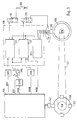
- a control device is shown schematically in FIG an internal combustion engine, in particular a diesel internal combustion engine, recorded.
- an injection valve 100 becomes the internal combustion engine at a certain time metered a certain amount of fuel.
- the exact The beginning and end of the fuel metering is determined using a first actuator set.
- this first Control element 110 is preferably a magnetic valve, that controls the fuel flow.
- that is Magnetic valve arranged in the area of a high pressure fuel pump and releases or blocks the fuel flow Fuel flow between a low pressure part and one High pressure part of the fuel pump.
- a second actuating element is provided, by means of the delivery rate, that is the amount of fuel injected is adjustable per revolution angle of the camshaft.
- This is preferably also a Solenoid valve, by means of which a pressure build-up or a pressure decrease is made possible in a hydraulic control element.
- This control element shifts the assignment between the Crankshaft of the internal combustion engine and the pump drive shaft.
- This is, for example, a Actuator for moving the cam disc at a Distributor injection pump.
- the first and the second actuating element are operated by a pump control unit 130 applied with control signals.
- the Pump control unit includes a quantity control 131, which the first control element 110 is supplied with control signals, a sprayer control 132, the second Actuating element 120 acted on with signals, and an IWZ evaluation 133, which evaluates the signals from a sensor 135.
- the sensor 135 scans an incremental wheel 136 that is on the Pump drive shaft or on the camshaft NW of the internal combustion engine is arranged.
- the increment wheel 136 includes a variety of markings, for example in one Distance of 3 ° are arranged.
- the evaluation 133 delivers a corresponding signal to the quantity control 131 and the Sprayer control 132.
- the camshaft NW is usually driven by a drive 137 driven by the crankshaft KW of the internal combustion engine.
- a segment wheel 140 with a number of markings corresponding to the number of cylinders 141 arranged. These markings are from a sensor 142 scanned.
- Sensor 142 provides the engine control unit 150 a signal NKW regarding the crankshaft speed.
- the pump control unit in turn is connected to an engine control unit 150 connected.
- the engine control unit 150 acts the pump control unit on the one hand via an interface e.g. CAN or via a direct line with signals.
- Via the interface e.g. CAN transmits the engine control unit 150 a signal QKS that the desired from the engine control unit Indicates the amount of fuel. Furthermore, it transmits a signal FBSK which corresponds to a target value for the start of funding, which is related to the crankshaft. Furthermore The engine control unit 150 transmits a further setpoint FBSN for the start of delivery, which is on the camshaft or Pump drive shaft is related and which sets the delivery rate.
- a switching means 155 selects either the ASS signal or the FBSK signal. In The switching means is in the operating mode considered here 155 in the position labeled 1.
- the engine control unit 150 transmits a speed signal relating to the crankshaft speed commercial vehicle to the pump control unit 130. There this signal is sent to the spray adjuster control 132.
- the sensor 142 detects the speed of the crankshaft and calculated starting of the speed and various other sizes such as in particular the accelerator pedal position a setpoint QKS for the amount of fuel to be injected and a setpoint for the Start of funding.
- the target value for the start of funding is between a setpoint FBSK related to the crankshaft and a value FBSN related to the camshaft is differentiated.
- the pump controller 130 sets these values in control signals for the first and second actuator.
- Starting from that Setpoint for the fuel quantity QKS and for the crankshaft-related Funding start setpoint FBSK calculates the quantity control 130 a signal for controlling the control element 110.
- a signal AE that the driving end and thus determines the end of fuel metering.
- the injected is also Fuel quantity defined.
- the injection adjuster control 132 calculates starting from a signal for triggering the start of funding setpoints FBSK and FBSN of the second actuating element 120.
- the delivery start setpoint FBSK which relates to the crankshafts the angular position of the crankshaft at which the fuel metering must start to get optimal combustion to reach.
- the target value for the start of funding FBSN which is based on the camshaft is covered gives the angular position of the Pump drive shaft at which injection begins should.
- the funding rate depends on this value.
- the pump controller 130 is optional via a switching means 155 the signal ASS or the signal FBSK supplied.
- the ASS signal determines an operating mode directly Start of control AB for the second control element 110
- Signal ASS immediately triggers signal AB for activation of the solenoid valve.
- another operating mode e.g. at Failure of this signal is used for the delivery start setpoint is related to the crankshafts as an input variable for the calculation and generation of the start of control in the pump control unit.
- Interface e.g. CAN becomes a pump map 200 with the Setpoint QKS for the amount of fuel to be injected. Furthermore, serve the related to the camshaft Funding start FBN, and a segment speed NS as input variables for the pump map 200. As an output variable the pump map provides the control period AD.
- the segment speed NS is the speed value which is derived from the Sensor 142 is detected. This is it by a value over a larger angular range of Crankshaft is averaged.
- Temperature compensation is used with the same input variables 210 applied, which additionally a temperature signal T processed a temperature sensor. Starting from these The temperature compensation 210 calculates a correction drive duration ADT.
- the correction drive period ADT and the Control duration AD of the pump map 200 are in one Link point 215 linked together. Preferably the two quantities are added or multiplied.
- the output signal of node 215 passes through a selection means 220 for a link point 225.
- Am The second input of the selection means 220 is the signal QKS regarding the target fuel quantity.
- the selection means 220 are controlled by a selection control 221.
- the second input of node 225 is negative Sign the output signal of the connection point 226 forwarded.
- the Signals of the switching timing 227 and the segment speed NS preferably linked multiplicatively.
- the output signal of node 225 passes through the nodes 230, 240 and 250 or immediately via the link point 260 to a selection means 270.
- Im Node 230 becomes the output signal of the node 225 with the output signal ADK1 of an acceleration correction 235 linked.
- Junction point 240 links the output signal of node 230 with the output signal ADK2 one Funding rate difference correction 245, which is an input variable Signal regarding the predicted start of delivery, the measured Start of funding and the control end signal AES processed.
- Junction 250 links the output signal of node 240 with a signal FBG regarding the measured start of funding.
- Junction point 260 links the output signal of Junction point 225 with a predicted funding start signal FBV.
- the selection means 270 routes the output signal of node 260 or the output signal of the link point 250 to the control end controller 280 further.
- the drive end controller 280 then applies the first Control element with the control end signal AES.
- Control duration AD is defined as a fuel volume for however, the exact fuel metering is the fuel mass required. Therefore, temperature compensation is used 210 based on the temperature T of the fuel Correction of the control period. For this the control duration AD linked in node 215 with the correction value ADT.
- the selection means 220 immediately instead of the output signal of the pump map AD the signal QKS regarding the target fuel quantity is used.
- the selection control 221 contains a threshold value check, which checks whether the one to be injected Amount of fuel or a corresponding signal, such as the drive duration, a threshold exceeds.
- the threshold corresponds to a fuel quantity value, which corresponds to a control duration that is shorter or only slightly larger than the computing time for the calculation of the map 200.
- the selection means 220 is external is controllable. For example, it can then be used for test purposes the signal QKS immediately as the control period AD below Bypassing the pump map can be used.
- the selection means under certain conditions the processed or the unprocessed Fuel quantity signal QKS as control duration signal AD selects. This can prevent in certain operating conditions, especially at low loads and high speeds injected impermissible amounts of fuel become.
- the control duration signal is in node 225 by the Solenoid valve switching time corrected. Usually passes between the control and the reaction of the solenoid valve a specific time. This time is called the switching time of the Solenoid valve designated. In the switching time specification 227 the value for the switching time is stored. In block 226 this switching time is linked to the segment speed. By Multiplying the segment speed by the switching time results there is an angle that corresponds to the switching time of the solenoid valve. The control duration in the connection point is around this angle 225 shortened and thus gives the funding or Dosing time FD.
- this funding period is added to the start of funding, so the target value AES results for the control end. As soon as the value for the funding period at the exit of the connection point 225 is present, this becomes in node 260 linked to the predicted FBV value for the start of funding and thus the final control setpoint AES is calculated. This value calculated in this way is then stored in the selection 270.
- the funding duration value in node 230 and 240 by means of the acceleration correction output signals ADK1 and the correction value ADK2 of the delivery rate difference correction 245 corrected.
- the funding period is corrected additively and / or multiplicatively.
- This additionally corrected value for the funding period is then at node 250 with the measured start of funding FBG linked. At the exit of the connection point 250 is then the setpoint for the control end AES Available.
- This complex correction requires a certain computing time, which are not available in all operating states stands. Especially at high speeds and small quantities the computing time is not sufficient.
- the selection 270 chooses in this case from the uncorrected activation duration and the predicted start of funding FBV calculated final control setpoint out.
- the selection chooses 270 the elaborately corrected and with the measured start of funding FBG calculates the setpoint for the control end of AES.
- the selection 270 is implemented as a memory.
- the Output signals of node 250 and 260 are as soon as they are stored in the memory of the selection 270.
- the drive end controller 280 then reads each current value.
- FIG. 3 shows the determination of the various start of delivery signals shown.
- the switching means 155 is either the signal ASS or a signal that the release of the solenoid valve indicates selected.
- the control circuit 154 controls the changeover switch 155 so that it is in position 1.
- the ASS signal that is generated by the engine control unit 51 is provided used.
- this is transmitted via the CAN interface Signal FBSK or a substitute signal that the start of funding or indicates the start of control AB used.
- the output signal of the switching means 155 is extrapolated 300, a GDP evaluation 310 and via a connection point 320 fed to an interpolation 330.
- the increment time TI is the time that passes between two pulses of the increment wheel 136.
- the filtered increment time TIG results, for example by averaging over several increments.
- the GDP evaluation 310 acts on node 345 to the second input of node 335. in the Junction point 345 becomes the output signal of the GDP evaluation 310 linked to the segment speed NS. This link is preferably multiplicative.
- the Segment speed NS is provided by evaluation 133. It corresponds to the current speed during an increment.
- the output signal of the BIP evaluation 310 arrives node 320.
- the output signal FBE of node 335 arrives at a funding start observer 350.
- the output signal of the Start of delivery observer 350 in turn reaches a limiter 355.
- the signal is at the output of limiter 355 FBV that corresponds to the assumed start of funding.
- the output signal FBGU of the interpolation 330 corresponds to that measured unlimited start of funding. This signal arrives on the one hand to the start of funding observer 350 and to a limiter 365. The signal is then at the output of the limiter FBG, which indicates the measured start of funding.
- the BIP evaluation 310 also outputs on the basis of the control signal a time window within which the GDP evaluation 310 detects the time of closing the solenoid valve. Starting from the time AB the activation of the Solenoid valve and the response of the solenoid valve results the switching time of the solenoid valve. The one in the current metering The determined value is used for the next metering.
- the limiter 355 limits this signal thus calculated permissible values. By linking with the correction value results the start of delivery FBN related to the camshaft.
- the measured start of funding FBG or FBGU is only now available when using interpolation 330 below Use the current increment time TIA at the time of Start of funding was calculated.
- the angular position of the Camshaft at the start of delivery, calculated from the interpolation is therefore only some time after the start of funding to disposal.
- the output signal FBGU of the interpolation 330 corresponds to the measured unlimited start of funding. By means of the limiter 365 this signal becomes permissible Values limited.
- the signal is the Funding start observer 350 fed.
- Start of funding signals can also be used to calculate end of funding signals be transmitted.
- start of funding signals from the drive end signal AE by means of an extrapolation below Taking into account the switching time of the solenoid valve and one Funding observer calculates a suspected funding end FEV. After the end of the funding, an interpolation is used corresponding to that shown in Figure 3 for the start of funding a measured end of delivery FEG is determined.
- a time variable is converted into an angle variable using an extrapolation before an event. To the event is then interpolated converted the same time variable into a measured angle variable.
- the time size is the start of funding and / or the driving end.
- the start of funding observer 350 is more detailed shown.
- the input signal FBE that the extrapolated Start of funding corresponds to a link 400, at the output of which the output signal FBVU, the unlimited corresponds to the assumed start of funding.
- the output signal is input to node 400 of a switching means 410.
- the Delay 420 becomes a limit with the output signal 430 acted upon. This is at the entrance to limitation 430 Output signal of an integrator 440.
- the integrator 440 is switched over a switching means 450 with the difference from the measured unlimited delivery start signal FBGU and the unlimited assumed FBVU start signal. For this purpose, these two signals are created using a connection point 455 linked.
- each cylinder there is an integrator 440, a limitation 430 and a delay element 420 are provided.
- the switching means 450 and 410 arrange them accordingly Cylinder of the internal combustion engine too.
- node 455 Based on the difference between the unlimited measured Start of funding FBGU and the unlimited assumed start of funding FBVU, node 455 forms a deviation.
- the switch 450 selects the corresponding integrator 440, assigned to the corresponding cylinder.
- the integrator integrates the difference between the two funding start values on.
- the output of the integrator is from limitation 430 up to permissible value ranges and limited below.
- Delay element 420 delays this signal by one camshaft revolution. This has to As a result, the next time the metering starts, the extrapolated start of funding FBE at node 400 around the output variable of the retarder 430 in the previous metering for the same cylinder is corrected.
- the funding start observer essentially provides a controller with integral behavior for each cylinder that the extrapolated value for the start of funding FBE by the difference between the measured and the assumed unlimited Corrected start of funding.
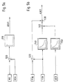
- the acceleration correction 235 is more detailed in FIG. 5a shown.
- the segment speed NS and a younger one Value for the segment speed NSA, which leads to a later Point in time will be a node 500 fed.
- This difference NB which is a measure of the acceleration represents the internal combustion engine, comes to a Amplifier 510, at whose output the correction value ADK1 for Available.
- the difference between the current value for the segment speed NS and another value NSA for the segment speed is weighted in the amplifier 510 and arrives at node 230 as correction variable ADK1.
- the influence is made by means of the acceleration correction 235 the change in speed is taken into account.
- the calculation of the Map 200 is very time-consuming because it is is a multi-dimensional map.
- the current changes Speed between the calculation of the map and the fuel metering, too high or too small amount of fuel metered. It is therefore intended that the amplifier 510 is dimensioned so that with increasing Speed reduces the delivery time and with falling speed the funding period is increased.
- the delivery rate difference correction 245 is shown in FIG. 5b.
- the amount of fuel injected essentially depends on the angle of the Camshaft.
- the delivery rate is usually not constant. This means the delivery rate is a function of the angular position of the Camshaft. This means that with the same control duration different amounts of fuel depending on the start of delivery be measured. Because the pump map at a very early The time must be calculated, here is only the assumed FBVN start of funding, which related to the camshaft is available. This value is only extrapolated and therefore does not correspond to the actual or measured Start of funding.
- Is the measured start of funding FBG before the end of metering known can be corrected accordingly by the rate difference correction 245 the error of based on the incorrect start of funding.
- This delivery rate difference correction 245 is more detailed in FIG. 5b shown.
- the measured start of funding FBG arrives via a node 520 to another Junction 530.
- FBV is expected to start funding on the one hand with a negative sign to the connection point 520 and via a map 540 and a connection point 545 also to the second input of the connection point 530.
- the target value AES for the control end is reached also via a map 550 to the second input of the Junction 545.
- the delivery rate is dependent on the maps 540 and 550 saved from the position of the camshaft.
- the map 540 is the funding rate at the time funding begins filed.
- the delivery rate is in the map 550 at the time of the setpoint for the AES control end.
- At the The correction value lies at the output of node 545 of the difference between the funding rate at the time the assumed start of funding FBV and the funding rate considered at the time of driving AES.
- this value is made up of the difference assumed start of funding FBV and measured funding start FBG connected.
- the signal ADK2, which at node 530 for Available takes into account the error caused by the Error occurs in the suspected start of funding.
Applications Claiming Priority (2)
| Application Number | Priority Date | Filing Date | Title |
|---|---|---|---|
| DE4425295A DE4425295A1 (de) | 1994-07-18 | 1994-07-18 | Verfahren und Vorrichtung zur Steuerung einer Brennkraftmaschine |
| DE4425295 | 1994-07-18 |
Publications (3)
| Publication Number | Publication Date |
|---|---|
| EP0694687A2 EP0694687A2 (de) | 1996-01-31 |
| EP0694687A3 EP0694687A3 (de) | 1998-06-03 |
| EP0694687B1 true EP0694687B1 (de) | 2001-11-21 |
Family
ID=6523436
Family Applications (1)
| Application Number | Title | Priority Date | Filing Date |
|---|---|---|---|
| EP95108988A Expired - Lifetime EP0694687B1 (de) | 1994-07-18 | 1995-06-10 | Verfahren und Vorrichtung zur Steuerung einer Brennkraftmaschine |
Country Status (4)
| Country | Link |
|---|---|
| US (1) | US5520152A (ja) |
| EP (1) | EP0694687B1 (ja) |
| JP (1) | JP3995112B2 (ja) |
| DE (2) | DE4425295A1 (ja) |
Families Citing this family (5)
| Publication number | Priority date | Publication date | Assignee | Title |
|---|---|---|---|---|
| DE19541927B4 (de) * | 1995-11-10 | 2010-01-07 | Robert Bosch Gmbh | Verfahren und Vorrichtung zur Steuerung und/oder Regelung einer Brennkraftmaschine |
| DE19744683A1 (de) | 1997-10-09 | 1999-04-15 | Bayerische Motoren Werke Ag | Kraftstoff-Einspritzvorrichtung für eine luftverdichtende Brennkraftmaschine |
| US6237567B1 (en) * | 1998-02-18 | 2001-05-29 | Isuzu Motors Limited | Fuel-injection system for engine |
| IT1310645B1 (it) * | 1999-07-28 | 2002-02-19 | Fiat Ricerche | Sistema di rilevazione delle fasi operative di un motore alternativo acombustione interna. |
| BR102018077407A2 (pt) * | 2018-12-28 | 2020-07-07 | Robert Bosch Limitada | método para injeção otimizada de combustível em sistemas de bombas de combustível diesel |
Family Cites Families (13)
| Publication number | Priority date | Publication date | Assignee | Title |
|---|---|---|---|---|
| CH483562A (de) * | 1967-11-10 | 1969-12-31 | Sulzer Ag | Verfahren für die Einführung von Brennstoff in die Arbeitszylinder einer mehrzylindrigen Kolbenbrennkraftmaschine sowie Vorrichtung zur Ausführung des Verfahrens |
| US3851635A (en) * | 1969-05-14 | 1974-12-03 | F Murtin | Electronically controlled fuel-supply system for compression-ignition engine |
| DE3130094A1 (de) * | 1981-07-30 | 1983-02-17 | Robert Bosch Gmbh, 7000 Stuttgart | Notsteuersystem fuer eine diesel-brennkraftmaschine |
| FR2523647A1 (fr) * | 1982-03-16 | 1983-09-23 | Renault Vehicules Ind | Systeme pour la commande de l'injection sur un moteur diesel |
| DE3405495A1 (de) * | 1984-02-16 | 1985-08-22 | Robert Bosch Gmbh, 7000 Stuttgart | Elektronisches steuersystem fuer die kraftstoffeinspritzung bei einer dieselbrennkraftmaschine |
| DE3436768A1 (de) * | 1984-10-06 | 1986-04-10 | Robert Bosch Gmbh, 7000 Stuttgart | Verfahren zur steuerung der kraftstoffeinspritzung bei brennkraftmaschinen und kraftstoffeinspritzsystem zur durchfuehrung des verfahrens |
| DE3614495A1 (de) * | 1986-04-29 | 1987-11-05 | Kloeckner Humboldt Deutz Ag | Kraftstoffeinspritzvorrichtung fuer eine brennkraftmaschine |
| JP2568603B2 (ja) * | 1988-01-11 | 1997-01-08 | 日産自動車株式会社 | 燃料噴射装置 |
| US4903669A (en) * | 1989-04-03 | 1990-02-27 | General Motors Corporation | Method and apparatus for closed loop fuel control |
| US5003953A (en) * | 1990-05-14 | 1991-04-02 | Chrysler Corporation | Transient fuel injection |
| DE4108639A1 (de) * | 1991-03-16 | 1992-09-17 | Bosch Gmbh Robert | System zur steuerung einer brennkraftmaschine |
| US5137000A (en) * | 1991-03-29 | 1992-08-11 | Cummins Electronics Company | Device and method for decreasing delays in fuel injected internal combustion engines |
| US5261366A (en) * | 1993-03-08 | 1993-11-16 | Chrysler Corporation | Method of fuel injection rate control |
-
1994
- 1994-07-18 DE DE4425295A patent/DE4425295A1/de not_active Ceased
-
1995
- 1995-06-06 US US08/469,340 patent/US5520152A/en not_active Expired - Lifetime
- 1995-06-10 EP EP95108988A patent/EP0694687B1/de not_active Expired - Lifetime
- 1995-06-10 DE DE59509858T patent/DE59509858D1/de not_active Expired - Lifetime
- 1995-07-17 JP JP18029595A patent/JP3995112B2/ja not_active Expired - Fee Related
Also Published As
| Publication number | Publication date |
|---|---|
| DE59509858D1 (de) | 2002-01-03 |
| EP0694687A2 (de) | 1996-01-31 |
| JPH0849593A (ja) | 1996-02-20 |
| JP3995112B2 (ja) | 2007-10-24 |
| US5520152A (en) | 1996-05-28 |
| EP0694687A3 (de) | 1998-06-03 |
| DE4425295A1 (de) | 1996-01-25 |
Similar Documents
| Publication | Publication Date | Title |
|---|---|---|
| EP0416265B1 (de) | Verfahren und Einrichtung zum Steuern der Kraftstoffeinspritzung | |
| DE4208002B4 (de) | System zur Steuerung einer Brennkraftmaschine | |
| EP0416270A1 (de) | Verfahren und Einrichtung zum Steuern und Regeln einer selbstzündenden Brennkraftmaschine | |
| DE19536038A1 (de) | Verfahren und Vorrichtung zur Steuerung der Antriebseinheit eines Kraftfahrzeugs | |
| DE19545221B4 (de) | Verfahren und Vorrichtung zur Steuerung einer Brennkraftmaschine | |
| DE4401828B4 (de) | Verfahren und Vorrichtung zur Vorhersage eines zukünftigen Lastsignals im Zusammenhang mit der Steuerung einer Brennkraftmaschine | |
| DE19831748B4 (de) | Verfahren und Vorrichtung zur Steuerung einer Brennkraftmaschine | |
| DE4315936A1 (de) | Einrichtung zum Steuern der Drosselöffnung eines Kraftfahrzeugmotors | |
| EP0694687B1 (de) | Verfahren und Vorrichtung zur Steuerung einer Brennkraftmaschine | |
| DE4120461C2 (de) | Verfahren und Einrichtung zur Steuerung eines magnetventilgesteuerten Kraftstoffzumeßsystems | |
| EP1005609B1 (de) | Verfahren zur steuerung der abgasrückführung bei einer brennkraftmaschine | |
| DE102005044266A1 (de) | Verfahren zum Betreiben einer Brennkraftmaschine und Brennkraftmaschine | |
| DE4040637C2 (de) | Elektronisches Steuersystem für die Kraftstoffzumessung bei einer Brennkraftmaschine | |
| DE4322270B4 (de) | Verfahren und Vorrichtung zur Steuerung einer Brennkraftmaschine | |
| DE19931823A1 (de) | Verfahren und Vorrichtung zur Steuerung einer Brennkraftmaschine | |
| EP0293367B1 (de) | Einrichtung zur regelung der laufruhe einer brennkraftmaschine | |
| DE19860398B4 (de) | Verfahren und Vorrichtung zur Steuerung der Kraftstoffzumessung in eine Brennkraftmaschine | |
| DE19547644B4 (de) | Verfahren und Vorrichtung zur Steuerung der Kraftstoffzumessung in eine Brennkraftmaschine | |
| DE4415640C2 (de) | Verfahren und Vorrichtung zum Steuern einer Brennkraftmaschine | |
| EP0708233B1 (de) | Verfahren und Vorrichtung zur Steuerung einer Brennkraftmaschine | |
| DE4020654C2 (de) | Regelverfahren in Verbindung mit einer Brennkraftmaschine und/oder einem Kraftfahrzeug und Regelvorrichtung zur Durchführung des Regelverfahrens | |
| DE4204091A1 (de) | Verfahren und einrichtung zur steuerung eines magnetventilgesteuerten kraftstoffzumesssystems | |
| DE3604200A1 (de) | Verfahren fuer die last- und drehzahlabhaengige verstellung des einspritzzeitpunkts bei dieselmotoren | |
| DE19541927B4 (de) | Verfahren und Vorrichtung zur Steuerung und/oder Regelung einer Brennkraftmaschine | |
| DE19833839C2 (de) | Verfahren und Vorrichtung zur Steuerung einer Kraftstoffzumeßeinrichtung |
Legal Events
| Date | Code | Title | Description |
|---|---|---|---|
| PUAI | Public reference made under article 153(3) epc to a published international application that has entered the european phase |
Free format text: ORIGINAL CODE: 0009012 |
|
| AK | Designated contracting states |
Kind code of ref document: A2 Designated state(s): DE FR GB IT SE |
|
| PUAL | Search report despatched |
Free format text: ORIGINAL CODE: 0009013 |
|
| AK | Designated contracting states |
Kind code of ref document: A3 Designated state(s): DE FR GB IT SE |
|
| 17P | Request for examination filed |
Effective date: 19981203 |
|
| GRAG | Despatch of communication of intention to grant |
Free format text: ORIGINAL CODE: EPIDOS AGRA |
|
| 17Q | First examination report despatched |
Effective date: 20010327 |
|
| GRAG | Despatch of communication of intention to grant |
Free format text: ORIGINAL CODE: EPIDOS AGRA |
|
| GRAH | Despatch of communication of intention to grant a patent |
Free format text: ORIGINAL CODE: EPIDOS IGRA |
|
| GRAH | Despatch of communication of intention to grant a patent |
Free format text: ORIGINAL CODE: EPIDOS IGRA |
|
| GRAA | (expected) grant |
Free format text: ORIGINAL CODE: 0009210 |
|
| AK | Designated contracting states |
Kind code of ref document: B1 Designated state(s): DE FR GB IT SE |
|
| REG | Reference to a national code |
Ref country code: GB Ref legal event code: IF02 |
|
| REF | Corresponds to: |
Ref document number: 59509858 Country of ref document: DE Date of ref document: 20020103 |
|
| ET | Fr: translation filed | ||
| GBT | Gb: translation of ep patent filed (gb section 77(6)(a)/1977) |
Effective date: 20020208 |
|
| PLBE | No opposition filed within time limit |
Free format text: ORIGINAL CODE: 0009261 |
|
| STAA | Information on the status of an ep patent application or granted ep patent |
Free format text: STATUS: NO OPPOSITION FILED WITHIN TIME LIMIT |
|
| 26N | No opposition filed | ||
| PGFP | Annual fee paid to national office [announced via postgrant information from national office to epo] |
Ref country code: SE Payment date: 20091222 Year of fee payment: 16 |
|
| PGFP | Annual fee paid to national office [announced via postgrant information from national office to epo] |
Ref country code: FR Payment date: 20100706 Year of fee payment: 16 |
|
| PGFP | Annual fee paid to national office [announced via postgrant information from national office to epo] |
Ref country code: IT Payment date: 20100624 Year of fee payment: 16 |
|
| PGFP | Annual fee paid to national office [announced via postgrant information from national office to epo] |
Ref country code: GB Payment date: 20100401 Year of fee payment: 16 Ref country code: DE Payment date: 20100824 Year of fee payment: 16 |
|
| REG | Reference to a national code |
Ref country code: SE Ref legal event code: EUG |
|
| GBPC | Gb: european patent ceased through non-payment of renewal fee |
Effective date: 20110610 |
|
| PG25 | Lapsed in a contracting state [announced via postgrant information from national office to epo] |
Ref country code: IT Free format text: LAPSE BECAUSE OF NON-PAYMENT OF DUE FEES Effective date: 20110610 |
|
| REG | Reference to a national code |
Ref country code: FR Ref legal event code: ST Effective date: 20120229 |
|
| REG | Reference to a national code |
Ref country code: DE Ref legal event code: R119 Ref document number: 59509858 Country of ref document: DE Effective date: 20120103 |
|
| PG25 | Lapsed in a contracting state [announced via postgrant information from national office to epo] |
Ref country code: FR Free format text: LAPSE BECAUSE OF NON-PAYMENT OF DUE FEES Effective date: 20110630 Ref country code: DE Free format text: LAPSE BECAUSE OF NON-PAYMENT OF DUE FEES Effective date: 20120103 |
|
| PG25 | Lapsed in a contracting state [announced via postgrant information from national office to epo] |
Ref country code: GB Free format text: LAPSE BECAUSE OF NON-PAYMENT OF DUE FEES Effective date: 20110610 |
|
| PG25 | Lapsed in a contracting state [announced via postgrant information from national office to epo] |
Ref country code: SE Free format text: LAPSE BECAUSE OF NON-PAYMENT OF DUE FEES Effective date: 20110611 |