EP0694665B1 - Ensemble constitué d'une serrure électrique de portière de véhicule automobile associée à ses moyens de commande et d'alimentation - Google Patents
Ensemble constitué d'une serrure électrique de portière de véhicule automobile associée à ses moyens de commande et d'alimentation Download PDFInfo
- Publication number
- EP0694665B1 EP0694665B1 EP95401757A EP95401757A EP0694665B1 EP 0694665 B1 EP0694665 B1 EP 0694665B1 EP 95401757 A EP95401757 A EP 95401757A EP 95401757 A EP95401757 A EP 95401757A EP 0694665 B1 EP0694665 B1 EP 0694665B1
- Authority
- EP
- European Patent Office
- Prior art keywords
- lock
- door
- vehicle
- fact
- vehicle according
- Prior art date
- Legal status (The legal status is an assumption and is not a legal conclusion. Google has not performed a legal analysis and makes no representation as to the accuracy of the status listed.)
- Revoked
Links
- 230000009471 action Effects 0.000 claims description 6
- 210000003195 fascia Anatomy 0.000 claims 1
- 230000002401 inhibitory effect Effects 0.000 claims 1
- 238000011022 operating instruction Methods 0.000 claims 1
- 239000003990 capacitor Substances 0.000 description 22
- 230000007257 malfunction Effects 0.000 description 5
- 230000005540 biological transmission Effects 0.000 description 3
- 238000010586 diagram Methods 0.000 description 3
- 239000000446 fuel Substances 0.000 description 3
- 230000035939 shock Effects 0.000 description 3
- 238000007599 discharging Methods 0.000 description 2
- 239000011521 glass Substances 0.000 description 2
- 210000000056 organ Anatomy 0.000 description 2
- 208000032953 Device battery issue Diseases 0.000 description 1
- 230000003213 activating effect Effects 0.000 description 1
- 230000008859 change Effects 0.000 description 1
- 230000000295 complement effect Effects 0.000 description 1
- 230000003247 decreasing effect Effects 0.000 description 1
- 230000006866 deterioration Effects 0.000 description 1
- 230000006870 function Effects 0.000 description 1
- 230000007246 mechanism Effects 0.000 description 1
- 238000000034 method Methods 0.000 description 1
- 230000008520 organization Effects 0.000 description 1
- 230000000750 progressive effect Effects 0.000 description 1
- 239000010453 quartz Substances 0.000 description 1
- 230000008439 repair process Effects 0.000 description 1
- 230000002441 reversible effect Effects 0.000 description 1
- VYPSYNLAJGMNEJ-UHFFFAOYSA-N silicon dioxide Inorganic materials O=[Si]=O VYPSYNLAJGMNEJ-UHFFFAOYSA-N 0.000 description 1
- 230000001629 suppression Effects 0.000 description 1
Images


Classifications
-
- E—FIXED CONSTRUCTIONS
- E05—LOCKS; KEYS; WINDOW OR DOOR FITTINGS; SAFES
- E05B—LOCKS; ACCESSORIES THEREFOR; HANDCUFFS
- E05B77/00—Vehicle locks characterised by special functions or purposes
- E05B77/22—Functions related to actuation of locks from the passenger compartment of the vehicle
- E05B77/24—Functions related to actuation of locks from the passenger compartment of the vehicle preventing use of an inner door handle, sill button, lock knob or the like
- E05B77/26—Functions related to actuation of locks from the passenger compartment of the vehicle preventing use of an inner door handle, sill button, lock knob or the like specially adapted for child safety
-
- E—FIXED CONSTRUCTIONS
- E05—LOCKS; KEYS; WINDOW OR DOOR FITTINGS; SAFES
- E05B—LOCKS; ACCESSORIES THEREFOR; HANDCUFFS
- E05B77/00—Vehicle locks characterised by special functions or purposes
- E05B77/22—Functions related to actuation of locks from the passenger compartment of the vehicle
- E05B77/24—Functions related to actuation of locks from the passenger compartment of the vehicle preventing use of an inner door handle, sill button, lock knob or the like
- E05B77/28—Functions related to actuation of locks from the passenger compartment of the vehicle preventing use of an inner door handle, sill button, lock knob or the like for anti-theft purposes, e.g. double-locking or super-locking
-
- E—FIXED CONSTRUCTIONS
- E05—LOCKS; KEYS; WINDOW OR DOOR FITTINGS; SAFES
- E05B—LOCKS; ACCESSORIES THEREFOR; HANDCUFFS
- E05B77/00—Vehicle locks characterised by special functions or purposes
- E05B77/46—Locking several wings simultaneously
- E05B77/48—Locking several wings simultaneously by electrical means
-
- E—FIXED CONSTRUCTIONS
- E05—LOCKS; KEYS; WINDOW OR DOOR FITTINGS; SAFES
- E05B—LOCKS; ACCESSORIES THEREFOR; HANDCUFFS
- E05B81/00—Power-actuated vehicle locks
- E05B81/54—Electrical circuits
-
- E—FIXED CONSTRUCTIONS
- E05—LOCKS; KEYS; WINDOW OR DOOR FITTINGS; SAFES
- E05B—LOCKS; ACCESSORIES THEREFOR; HANDCUFFS
- E05B81/00—Power-actuated vehicle locks
- E05B81/54—Electrical circuits
- E05B81/80—Electrical circuits characterised by the power supply; Emergency power operation
- E05B81/82—Electrical circuits characterised by the power supply; Emergency power operation using batteries other than the vehicle main battery
-
- E—FIXED CONSTRUCTIONS
- E05—LOCKS; KEYS; WINDOW OR DOOR FITTINGS; SAFES
- E05B—LOCKS; ACCESSORIES THEREFOR; HANDCUFFS
- E05B77/00—Vehicle locks characterised by special functions or purposes
- E05B77/02—Vehicle locks characterised by special functions or purposes for accident situations
- E05B77/12—Automatic locking or unlocking at the moment of collision
-
- G—PHYSICS
- G07—CHECKING-DEVICES
- G07C—TIME OR ATTENDANCE REGISTERS; REGISTERING OR INDICATING THE WORKING OF MACHINES; GENERATING RANDOM NUMBERS; VOTING OR LOTTERY APPARATUS; ARRANGEMENTS, SYSTEMS OR APPARATUS FOR CHECKING NOT PROVIDED FOR ELSEWHERE
- G07C9/00—Individual registration on entry or exit
- G07C9/00174—Electronically operated locks; Circuits therefor; Nonmechanical keys therefor, e.g. passive or active electrical keys or other data carriers without mechanical keys
- G07C2009/00753—Electronically operated locks; Circuits therefor; Nonmechanical keys therefor, e.g. passive or active electrical keys or other data carriers without mechanical keys operated by active electrical keys
- G07C2009/00769—Electronically operated locks; Circuits therefor; Nonmechanical keys therefor, e.g. passive or active electrical keys or other data carriers without mechanical keys operated by active electrical keys with data transmission performed by wireless means
Definitions
- the invention relates to the assembly consisting of a lock electric motor vehicle door and its means of control and supply.
- each vehicle lock is connected to a centralized box, which receives the energy to be distributed to the locks, and returns it to the locks in based on the information it receives itself from the different locks.
- a lock is controlled by a plurality of organs, which go each supply, depending on the position of the switch which is associated, electrical information that must be brought back to the box centralized electronics: the lock is controlled by the pallet or outer handle, by the pallet or inner handle, by the barrel for the front doors and by the "child lock” devices for the rear doors.
- the lock is controlled by the pallet or outer handle, by the pallet or inner handle, by the barrel for the front doors and by the "child lock” devices for the rear doors.
- the object of the invention is to reduce the transport links of energy between a lock and a centralized unit.
- Another object of the invention is to propose a set of control and supply of an electric vehicle lock automobile, which considerably reduces the bundle of wires connected to each electric lock on the vehicle.
- each electronic module associated with a lock is connected to the modules electronics associated with other door locks of the same vehicle, so that an instruction given on one of the locks is affects other locks; but we see that with this system, it is sufficient to establish a connection between the vehicle locks by a connector, which carries information but does not carry no energy. We therefore see that, in this way, we simplify considerably the bundles of wires associated with each lock electric vehicle, which results in a cost price considerably decreased.
- the invention therefore relates to a motor vehicle comprising a plurality of electric door locks associated with their respective control and supply means, the opening of each lock being electrically secured by the operation of a actuator powered by vehicle battery, power supply of each lock is controlled by an electronic module installed in the door to which the lock is associated, said module receiving on the one hand, the electrical energy of the vehicle battery and, on the other hand, the instructions provided by the control bodies associated with the lock controlled by said module, and being connected to at least one other electric door lock of the vehicle by a connector for transmit only information signals relating to the state of condemnation or unlocking of the lock towards said other electric door lock, characterized in that it comprises, preferably in the vicinity of its dashboard, a central box intended to receive condemnation / unlocking instructions locks by remote control, said housing being connected directly to the vehicle battery by connections for its supply of energy and connected by the aforementioned connector to the door locks for the transmission of these instructions to the associated electronic modules.
- each module is supplied directly in energy from the wires that are already in the door and that are connected to the vehicle battery, for example the wires that power the electric window motor incorporated in the door.
- the lock according to the invention is associated with two door handles, one inside and the other outside, the lock control elements comprising two switches each associated with one of said handles for generate the power supply for the lock actuator in order to cause the opening of said lock.
- the lock controls also include a two-position switch associated with a lock cylinder: this allows control with the key, which operates the barrel, the condemnation or unlocking of the lock; when the lock is condemned, the opening can no longer be caused by the operation of the exterior handle but only for questions safety, by the operation of the interior handle.
- the switch associated with the interior operating handle can be in series with a switch to inhibit the opening of the door by the interior door handle: this prevents occupants of the passenger compartment, especially children, can open inside the rear doors of the vehicle.
- the switches associated with the two handles operation of the lock are in series with a contactor arranged in a central box receiving instructions by remote control operation of said contactor, this contactor making it possible to inhibit the opening of the vehicle door by the interior handle of said door: a vehicle break-in is thus avoided by a simple breakage of glass allowing access to the interior handle, which remains active in simple conviction.
- the central box receives by remote control of the locking or unlocking instructions of the lock, in which case it transmits the information on the connector of the lock for operation by the electronic module of said lock ; of course, said connector passes this information on all the locks, which are linked to it.
- the connector which is associated with each vehicle door lock consists of a wire carrying condemnation order information, a second thread carrying the unlocking control information and, if applicable if necessary, a third thread carrying the super-conviction information.
- the connector can be connected to an annex box supplying at least one auxiliary actuator associated with a vehicle lock other than a door lock, for example a trunk lock or a fuel door lock; the unlocking wire of the connector can be linked to a shock detector so that in case of shock the whole door locks be unlocked.
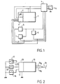
- an electrically controlled door lock for an automotive vehicle has been designated by 1.
- the lock 1 is associated with a backup battery 2 and an electronic interface 3.
- the battery 2 and the interface 3 are linked to the lock which is placed inside the vehicle door with which said lock is associated.
- the energy for controlling the lock 1 comes from a centralized housing 4 which is itself connected to the battery 4 a of the vehicle.
- the control members of the lock 1 consist of an exterior door handle 5, an interior door handle 6 and a lock cylinder 7: the presence of the cylinder 7 shows that the lock of FIG. 1 is a vehicle door lock.
- the members 5, 6 and 7 are in fact switches, the opening or closing states of which are transmitted to the centralized box 4 and to the electronic interface 3.
- interface 3 detects the absence and replaces the energy of the vehicle battery with the energy of the backup battery 2, which is associated with the lock. This provision is particularly advantageous in the event of an accident because the four doors of the vehicle are generally not damaged simultaneously, so that there is always at least one lock 1 capable of being opened by means of the battery energy of rescue 2.
- FIG. 2 represents an electric lock 10 on the door of a motor vehicle.
- the emergency device which is associated with this lock can be any and is not shown.
- the lock 10 is associated with control members 15, 16, 17 which are respectively analogous to the members 5, 6, and 7 of the lock of FIG. 1.
- the lock 10 is associated with an electronic module 13 which directly receives the energy required for the opening or closing operation of the lock, this energy being taken from the door of the motor vehicle with which the lock 10 is associated, for example on the driver supplying the motor of the electric window regulator.
- the lock 10 is connected by the two wires 18 a , 18 b of a connector 18 to the other electric locks of the vehicle.
- a lock of this type avoids the wire harness, which connected the centralized box, associated with the lock of Figure 1, to the door where the lock 1 was and its control means 5, 6 and 7.
- the role of the centralized box 4 is held by the module 13 and, alone, the connector 18 leaves from the lock 10 in the direction other doors of the vehicle to transmit to the locks of these information on the state of conviction or unlocking of lock 10, information which will enable modules associated with said other locks, to put said other locks in the same state of conviction or unlocking as the lock 10 itself.
- This considerable simplification of the beam of wires from each lock beneficially affects the price of returns from the assembly, all the more so since the wires of connector 18 do not carry no energy and can therefore be children of low section.
- FIG 3 there is shown schematically all of the four door locks 20 a , 20 b , 20 c , 20 d of a vehicle, each of these locks being of the type shown in Figure 2.
- the connector (28, 28b) is also connected to an attached housing 29, which receives a power supply from the vehicle battery and which supplies two actuators 27 a, 27 b, for the first to the locking / unlocking the boot and the second on opening / closing the fuel door.
- FIG 4 there is shown an implementation of the invention in the context of the embodiment of Figure 3, in which the four electric locks of the four doors of a vehicle can be controlled by a remote control transmitter unit 32
- each of the locks is supplied directly by the vehicle battery.
- the transmitter unit 32 is associated with a receiver unit 33 powered by the vehicle battery.
- the transmitter box 32 includes a transmission control (locking / unlocking) and a "super-locking" transmission control, which, in known manner, prevents, when it is in place, any operation of opening the locks of the vehicle by the interior handles.
- the information relating to the locking or unlocking is provided to the locks by the central box 33, respectively on the wires 38 a and 38 b of the connector, while the information relating to the super locking is supplied on the wire 38 c .
- the locks 31 c and 31 d include “child lock” switches designated by 34 c and 34 d respectively, these switches making it possible to inhibit any opening of the lock by the interior handle of the door.
- the switches 34 c , 34 d can be controlled by a push button arranged in the door edge or by a button arranged on the dashboard.
- the son 38 a and 38 b of the central housing 33 are also used for controlling an attached housing 39 similar to the housing 29 of the embodiment of Figure 3, the attached housing 39 supplying Annexes actuators 37 a, 37 b identical to the actuators 27a , 27 b of the embodiment of FIG. 3.
- FIG 5 there is shown in more detail an assembly according to the invention of the type which has been roughly defined on the Figure 4.
- the four locks electric vehicle doors are each associated with a backup battery like the locks shown in the Figure 1.
- the device of Figure 5 has a remote control and it is therefore provided with a central box associated with a receiver decoder of remote control; in addition, it includes auxiliary actuators intended in particular to the lock of the vehicle trunk and to the lock of the petrol door, these auxiliary actuators being associated with a housing annex, which is incorporated in the central box to constitute with it a single centralized unit.
- FIG. 5 therefore represents an assembly, which comprises four electric locks 131 a , 131 b , 131 c , 131 d intended for the four doors of a motor vehicle; the locks 131 a and 131 b are intended for the two front doors and the locks 131 c and 131 d are intended for the two rear doors.
- Each of these locks incorporates a backup battery and an electronic circuit, which combines the electronic interface associated with the backup battery and the electronic module due to the direct connection of each lock to the electrical supply of the vehicle battery; this electronic circuit is, in the drawing, shown diagrammatically, for each lock, by a rectangle and designated respectively by 103 a , 103 b , 103 c , 103 d ; it is shown in detail in Figure 6.
- Each of the locks is connected directly to the vehicle battery by connection to the wire which feeds the window regulator incorporated in the door; this connection has been schematized by the connections 150 a , 150 b , 150 c , 150 d in the direction of earth and 151 a , 151 b , 151 c , 151 d in the direction of the positive pole of the battery.
- the two locks 131 a and 131 b are each associated with three control members, namely a switch 105 a , 105 b respectively, corresponding to the external handle, a switch 106 a , 106 b respectively, corresponding to the internal handle of the door and a switch 107 a , 107 b respectively, corresponding to the door barrel, that is to say the safety barrel which is capable of being operated by the user with a key for opening the door.
- the barrel switch is a two-position switch which therefore allows the locking or unlocking of the lock to be controlled, depending on the direction of rotation of the key.
- the electric locks 131 c and 131 d are associated with two control members, namely, on the one hand, the switch 105 c , 105 d respectively, corresponding to the exterior door handle and, on the other hand, the switch 106 c , 106 d respectively, corresponding to the interior door handle; in addition, these locks are associated with a switch 134 c , 134 d respectively, which can be operated independently of the other two and which is in series with the switch 106 c , 106 d respectively: this switch 134 c , 134 d corresponds to the "child condemnation", that is to say a ban on opening the rear doors from the interior handle; the "child lock” switch can be a manual push button located in the door edge or a control button brought back to the dashboard.
- the four locks of the vehicle are interconnected by a connector capable of transporting information relating to the state of locking, unlocking or super-locking of the locks.
- the connector comprises three wires 138 a , 138 b , 138 c : the wire 138 a carries information relating to the conviction; wire 138 b carries the information relating to the unlocking; wire 138 c carries information relating to the super-conviction.
- the super-condemnation is shown diagrammatically in the drawing in FIG.
- a switch 152 which is in series with the switches 105 a , 105 b , 105 c and 105 d and 106 a , 106 b , 106 c , 106 d associated with the interior and exterior door handles.
- the deadlocking switch 152 is disposed within the central unit 133, which receives the two connections 153, 154, remote control commands provided by a receiver-decoder 133 associated with the central unit 133 and possibly integrated with it.
- the receiver 133 a receives its instructions from a remote control unit 132, which is operated remotely by the user.
- the instructions are of two types: on the one hand, the locking / unlocking instructions, which pass through the connection 154, and, on the other hand, the super-condemnation instructions which pass through the connection 153, which is connected to the switch 152 to cause it to open or close.
- the centralized unit 133 is connected directly to the vehicle battery by the connections 155, 156.
- a shock detector 140 is capable of sending unlocking information by the connection 157 on the wire 138 b .
- the centralized unit 133 is, moreover, connected by the connections 158, 159 to two auxiliary actuators 137 a , 137 b associated respectively with the electric locks of the boot and of the fuel door of the vehicle. Finally, the centralized unit 133 can receive additional information such as, for example, that shown by the connection 141 coming from alarm circuits or presence detectors. Of course, the centralized unit 133 can control a light-emitting diode to signal the state of the switch 152 and, consequently, the state of super-locking of the vehicle locks.
- the backup battery intended for each of the locks is integrated inside the lock, this which is particularly advantageous in the event of a vehicle accident since the four doors of the vehicle are generally not simultaneously damaged, so that at least one of the locks is capable of operating with its backup battery, even if the battery of the vehicle is out of service; on the other hand, since the energy required to operate an electric lock is taken inside the door with which said lock is associated, there is no energy transport link between a lock and the centralized unit 133, which may be in the vicinity of the dashboard and is itself connected for its operation to the vehicle battery.
- the only existing connections, between the centralized unit 133 and the four electric locks of the vehicle, are constituted by the three wires 138 a , 138 b , 138 c which form a three-wire connector; said wires carry only information signals and can therefore be very fine; it follows that the cost price of such a connector, as well as its connection cost, is extremely reduced compared to what it was necessary to achieve when, as in the prior art, the supply of all the vehicle locks were carried out by a centralized unit, which provided only the energy necessary to open all the locks.
- FIG 6 there is shown the detailed diagram of the electronic circuit, which is associated with each of the locks 131 a , 131 b , 131 c , 131 d of the assembly of Figure 5.
- This electronic circuit includes a switch 134 associated to the "condemnation-child" and barrel controls 161, 162 acting, the first in the sense of unlocking and the second in the direction of the condemnation; in this way, this circuit can be used both for the front doors and for the rear doors, it being understood that the functions associated with these elements will be used one or the other, that which is not used does not interfere for the operation of the assembly.
- the electronic circuit shown in Figure 6 is connected to the positive pole of the vehicle battery via terminal 200 and to the pole negative, that is to say to ground, via terminal 201. All masses, which are shown in the circuit, are therefore connected to terminal 201 of the printed card carrying the circuit.
- the backup battery associated with the card is shown in 202: it is a 9 volt battery which is connected by a diode 205 at point 203 of the circuit, a capacitor 204 being provided in parallel for interference suppression. Point 203 of the circuit is also connected to terminal 200 via a diode 206 and of a resistance 207. It can therefore be seen that with this mounting the battery of backup 202 will supply its energy if the voltage on terminal 200 becomes below a threshold of approximately 9 volts.
- the tension at point 203 of circuit enables the elements 208 which are supplied by terminal 208 described below and which ensure the operation of the lock electric in case of power supply failure due to the battery. But he is necessary to power the various electronic components of the card, to have a stabilized voltage protected against surges, ripples and noise.
- This protection is obtained thanks to the subset designated by 209, which subset provides a stabilized voltage on terminal 210; the subset 209 includes, in particular, a Zener diode 211, which avoids overvoltages, and a transistor-ballast 212.
- a "NAND" door 213 has its entry 214 connected to the terminal 210 and its input 215 connected to the power supply 200 by through a diode 216 and a resistor 217.
- the same input 215 is connected to point 218 itself connected to ground by the intermediary of two branches in parallel: the first comprises a resistor 219 and the second has a resistor 220 and a capacitor 221 of about 5 mF.
- the tension at point 218, through play of the ratio of resistors 219 and 220, is approximately one third of the voltage across capacitor 221. If the voltage on input 215 is below a threshold, entry 215 is considered to be at level low and, since entry 214 is always high, the exit from door 213 is high. So we see that, if the output 222 of door 213 is high, this means that the voltage of the capacitor 221 is less than a given value which is set, for example 20 volts, and that the power supplied by the battery of the vehicle is out of order.
- a multivibrator 223, operating with a Schmitt trigger controls the conduction of transistor 224 by a base voltage in slots and, as soon as the transistor 224 opens, the coil 225, being always connected to the terminal 208, allows charging of the capacitor 221 via the diode 226.
- This charging is carried out according to the modality detailed below, as long as the capacitor 221 has not reached the voltage that we have fixed, namely 20 volts.
- input 215 from door 213 goes high, so that outlet 222 goes at the low level, which blocks the transisor 224 and stops the charging of the capacitor 221.
- the sub-assembly 227 comes into operation to trigger an audible alarm produced by a quartz 228.
- the charge of the capacitor 221 by the coil 225 is carried out by limiting the current in the coil to avoid over-discharging the backup battery 202 which supplies the energy.
- the base of transistor 224 is high, the current settles in coil 225 until it reaches a value considered as the maximum tolerable.
- the base of transistor 229 is brought to a sufficient voltage for transistor 229 to become passing and this change of state is reflected on input 230 of the multivibrator 223 so that the output of this multivibrator goes to low level, which blocks transistor 224.
- the coil 225 being charged then discharges through diode 226 to the capacitor 221 and the subsequent charging phase occurs when the output of the multivibrator 223 returns to high level.
- This succession of load sequences are carried out as long as output 222 remains at level high. In this way, the voltage is brought to the terminals of the capacitor 221 at the value of 20 volts while limiting the charging current.
- the capacitor 221 loses its charge gradually over time, nothing happens as long as the tension of the vehicle battery remains normal on terminal 200. However, if this voltage drops or disappears, the input 215 goes to a low level, which results in additional charge of the capacitor 221 and, simultaneously activating the horn 227. the driver of the vehicle is immediately warned of a malfunction of its battery, which allows it to ensure the repair faster. Furthermore, if the battery voltage on the terminal 200 is normal, the capacitor 221 is charged directly by the coil 225, the diode 226 and the resistor 280 and the voltage across capacitor 221 is 12 volts. In others terms, the voltage of capacitor 221 is only increased to 20 volts in the event of a battery failure. When the battery voltage is normal, the voltage across capacitor 221 is 12 volts or returns to 12 volts by progressive loss if it had been increased to 20 volts following a malfunction; this precaution allows extend the life of capacitor 221.
- the electric lock actuator with which it is associated the circuit of FIG. 6 is a direct current motor 231, the control is carried out by transistor 232 associated with its terminal negative; transistor 232 is a MOS transistor.
- transistor 232 is a MOS transistor.
- motor power takes place through diode 233; on the contrary, when the tension of the battery has disappeared, power to the 231 motor is through the diode 234 by discharging the capacitor 221.
- the Zener diode 235 connected between earth and point 236 located between the motor 231 and the transistor 232, is only intended to protect transistor 232 against overvoltages inherent in the operation of the motor 231.
- a circuit 237 comprising a resistor and a capacitor, circuit which allows a time delay for motor supply 231. This precaution avoids powering the motor 231 for a very long time, the latter remaining blocked at the end of the race, which would cause the deterioration of the engine 231; this could happen if, for example, we acted for a long time on the handle of door by closing the corresponding switch. For control the power supply to the 231 motor, so act on the basis of transistor 232 to bring this base to the high level.
- This base is connected by line 238 to the exit of a "NON OR" door 239, of which one of the inputs is connected to line 222 while the other input is connected to the switches of the interior and exterior handles of door; we have designated by 240 the terminal of the circuit on which arrives the interior handle switch and by 241 the terminal on which comes the switch on the outside handle.
- Switch 134 of the safety "child conviction” is serial on the line from the terminal 240. The operation of a handle switch causes the setting to the ground of the corresponding terminal 240, 241. If terminal 240 is grounded, switch 134 being assumed to be closed, input 242 of door 239 is at a low level.
- the transistor 243 must be passing, that is to say that its base must be at the high level.
- the base of transistor 243 is connected to the output of a "RS" type flip-flop 244 the two inputs 245, 246 of which are connected to the terminals respectively unlocking 161 and locking 162 of the switch double position of the lock cylinder. If the switch associated with the terminal 161 was operated to bring the unlocking of the lock, line 245 has been temporarily grounded and, in this case, the output of flip-flop 244 is in the high state, which allows the 231 motor control by the external handle.
Landscapes
- Health & Medical Sciences (AREA)
- Child & Adolescent Psychology (AREA)
- Lock And Its Accessories (AREA)
Description
- la figure 1 représente schématiquement les connexions d'une serrure, ladite serrure étant reliée à un boítier centralisé de l'état de la technique ;
- la figure 2 représente schématiquement une autre serrure, ladite serrure étant associée à un dispositif de secours de type quelconque non représenté ;
- la figure 3 représente schématiquement un ensemble de quatre serrures de portière selon la figure 2 reliées entre elles par leur connecteur et associées à un boítier annexe qui permet la commande de deux actionneurs complémentaires ;
- la figure 4 représente un ensemble selon l'objet de l'invention associé à une télécommande, qui peut agir par l'intermédiaire d'une unité centralisée sur les quatre serrures de portière et sur les deux actionneurs annexes du véhicule, les deux portières arrière étant équipées de "condamnation-enfant" ;
- la figure 5 représente un schéma détaillé d'un ensemble correspondant à la figure 4 et pourvu d'une batterie de secours, qui comporte, en outre, une télécommande permettant de commander à distance la condamnation ou la décondamnation des serrures ainsi que la super-condamnation ;
- la figure 6 représente le schéma électronique d'un module associé à l'une des serrures de l'ensemble représenté sur la figure 5.
Claims (12)
- Véhicule automobile comportant une pluralité de serrures électriques (10 ; 20a, 20b, 20c, 20d, ; 31a, 31b, 31c, 31d 131a, 131b, 131c, 131d) de portières associées à leurs moyens de commande et d'alimentation respectifs, l'ouverture de chaque serrure étant assurée électriquement par la manoeuvre d'un actionneur (231) alimenté par la batterie du véhicule, l'alimentation électrique de chaque serrure est pilotée par un module électronique (13) implanté dans la portière à laquelle la serrure est associée, ledit module (13) recevant d'une part, l'énergie électrique de la batterie du véhicule et, d'autre part, les instructions fournies par les organes de commande (15, 16, 17) associés à la serrure pilotée par ledit module, et étant relié à au moins une autre serrure électrique de portière du véhicule par un connecteur (18) pour transmettre uniquement des signaux d'information relatifs à l'état de condamnation ou de décondamnation de la serrure vers ladite autre serrure électrique de portière, caractérisé par le fait qu'il comporte, de préférence au voisinage de son tableau de bord, un boítier central (33) destiné à recevoir des instructions de condamnation/décondamnation des serrures par télécommande, ledit boítier étant relié directement à la batterie du véhicule par des connexions (155, 156) pour son alimentation en énergie et relié par le connecteur précité (18) aux serrures de portière pour la transmission de ces instructions aux modules électroniques associés.
- Véhicule selon la revendication 1, caractérisé par le fait que chaque module est alimenté directement en énergie à partir des fils qui se trouvent déjà dans la portière et qui sont reliés à la batterie du véhicule, par exemple les fils qui alimentent le moteur du lève-glace électrique incorporé dans la portière.
- Véhicule selon la revendication 1 ou 2, caractérisé par le fait que le module électronique (13) est implanté dans la serrure (10).
- Véhicule selon l'une des revendications 1 à 3, caractérisé par le fait que la serrure (10 ; 131a, 131b, 131c, 131d) est associée à deux poignées de portière, l'une intérieure (16 ; 106a, 106b, 106c, 106d) et l'autre extérieure (15 ; 105a, 105b, 105c, 105d), les organes de commande de la serrure comportant deux interrupteurs associés chacun à l'une desdites poignées et insérés sur l'alimentation de l'actionneur (231).
- Véhicule selon l'une des revendications 1 à 4, caractérisé par le fait que les organes de commande de la serrure comportent un interrupteur à deux positions associé à un barillet de serrure (17; 107a, 107b, 107c, 107d).
- Véhicule selon la revendication 4, caractérisé par le fait que l'interrupteur associé à la poignée de manoeuvre intérieure est en série avec un interrupteur (34c, 34d 134c, 134d ; 134) permettant d'inhiber l'ouverture de la portière par la poignée intérieure de ladite portière.
- Véhicule selon la revendication 4 ou 6, caractérisé par le fait que les interrupteurs associés aux deux poignées de manoeuvre de la serrure sont en série avec un contacteur (152) disposé dans un boítier central (33) recevant par télécommande les instructions de manoeuvre dudit contacteur, ce contacteur permettant d'inhiber l'ouverture de la portière du véhicule par action sur la poignée intérieure pour établir un état de super-condamnation.
- Véhicule selon l'une des revendications 1 à 7, caractérisé par le fait que le connecteur (18), qui est associé à chaque serrure de portière du véhicule, est constitué par un fil (18a, 38a) transportant l'information de commande de condamnation, un deuxième fil (18b, 38b) transportant l'information de commande de décondamnation et, dans le cas d'un véhicule selon la revendication 6, un troisième fil (38c) transportant l'information de super-condamnation.
- Véhicule selon l'une des revendications 1 à 8, caractérisé par le fait que le connecteur (18) est relié à un boítier annexe (39) alimentant au moins un actionneur annexe (37a, 37b) associé à une serrure du véhicule autre qu'une serrure de portière.
- Véhicule selon la revendication 8, caractérisé par le fait que le fil de décondamnation (38c) du connecteur est lié à un détecteur de choc (140).
- Véhicule selon la revendication 9, caractérisé par le fait que le boítier central et le boítier annexe sont réunis en une seule unité centralisée (133).
- Véhicule selon la revendication 11 caractérisé par le fait que l'unité centralisée (133) reçoit des informations d'alarme et fournit leur exploitation sur le connecteur (18).
Applications Claiming Priority (2)
| Application Number | Priority Date | Filing Date | Title |
|---|---|---|---|
| FR9409298 | 1994-07-27 | ||
| FR9409298A FR2723127B1 (fr) | 1994-07-27 | 1994-07-27 | Ensemble constitue d'une serrure electrique de portiere de vehicule automobile associee a ses moyens de commande et d'alimentation |
Publications (2)
| Publication Number | Publication Date |
|---|---|
| EP0694665A1 EP0694665A1 (fr) | 1996-01-31 |
| EP0694665B1 true EP0694665B1 (fr) | 1999-04-28 |
Family
ID=9465798
Family Applications (1)
| Application Number | Title | Priority Date | Filing Date |
|---|---|---|---|
| EP95401757A Revoked EP0694665B1 (fr) | 1994-07-27 | 1995-07-25 | Ensemble constitué d'une serrure électrique de portière de véhicule automobile associée à ses moyens de commande et d'alimentation |
Country Status (4)
| Country | Link |
|---|---|
| EP (1) | EP0694665B1 (fr) |
| DE (1) | DE69509317T2 (fr) |
| ES (1) | ES2131287T3 (fr) |
| FR (1) | FR2723127B1 (fr) |
Families Citing this family (21)
| Publication number | Priority date | Publication date | Assignee | Title |
|---|---|---|---|---|
| DE19633202C1 (de) * | 1996-08-17 | 1997-09-11 | Kiekert Ag | Steueranlage für ein Kraftfahrzeug mit zusätzlicher Notbetriebseinrichtung |
| DE29617425U1 (de) | 1996-10-08 | 1996-11-28 | Postler, Karl, Dipl.-Ing., 46562 Voerde | Einbau einer automatischen Ansteuerung elektrischer Schließeinrichtungen an Fahrzeugen auf "Öffnen" bei vorgegebener Zeitverzögerung und Negativbeschleunigung nach einem Unfall |
| DE19646810C2 (de) * | 1996-11-13 | 1999-02-04 | Kiekert Ag | Kraftfahrzeugtürverschluß mit Schloßsystem, Schließsystem und auf eine Auswerteelektronik arbeitender Einrichtung Abfrage der Funktionsstellungen des Schließzylinders, die mit Hallsensor-Chips arbeitet |
| DE19702689B4 (de) | 1997-01-25 | 2006-03-23 | Kiekert Ag | Kraftfahrzeugtürverschluss mit Schlosssystem sowie auf das Schlosssystem arbeitendem Schließsystem und elektronischer Steuer- und/oder Kontrolleinrichtung |
| GB2331119A (en) * | 1997-08-06 | 1999-05-12 | Rockwell Lvs | Vehicle door mechanism with associated rechargeable electric energy storage |
| US6463773B1 (en) * | 1999-03-05 | 2002-10-15 | Strattec Security Corporation | Electronic latch apparatus and method |
| CA2299921A1 (fr) | 1999-03-05 | 2000-09-05 | Strattec Security Corporation | Methode et appareil de verrouillage modulaire |
| US6786070B1 (en) | 1999-03-05 | 2004-09-07 | Sirattec Security Corporation | Latch apparatus and method |
| US6575505B1 (en) | 2000-10-25 | 2003-06-10 | Strattec Security Corporation | Latch apparatus and method |
| US6776442B2 (en) | 2001-01-09 | 2004-08-17 | Strattec Security Corporation | Latch apparatus and method |
| WO2006096600A2 (fr) | 2005-03-05 | 2006-09-14 | Southco, Inc. | Verrou a cliquet rotatif et commutateur a bascule |
| CN1963874B (zh) * | 2006-12-06 | 2010-07-21 | 中国科学院电工研究所 | 一种带can接口的车用中控锁控制装置 |
| CN102322185B (zh) * | 2011-06-01 | 2013-09-11 | 汉王科技股份有限公司 | 一种智能门锁 |
| TW201326526A (zh) * | 2011-12-30 | 2013-07-01 | Li-shi LIAO | 電磁門鎖震動偵測式節能省電裝置 |
| DE102012018452A1 (de) | 2012-09-18 | 2014-03-20 | GM Global Technology Operations, LLC (n.d. Ges. d. Staates Delaware) | Fahrzeugtür und damit ausgestattetes Fahrzeug |
| EP3392434A4 (fr) * | 2015-12-16 | 2019-08-07 | Mitsui Kinzoku ACT Corporation | Dispositif de serrure de porte d'automobile |
| DE102019127112A1 (de) * | 2019-10-09 | 2021-04-15 | Kiekert Aktiengesellschaft | Kraftfahrzeugschloss insbesondere Kraftfahrzeugtürschloss |
| DE102019127109A1 (de) * | 2019-10-09 | 2021-04-15 | Kiekert Aktiengesellschaft | Kraftfahrzeugschloss, insbesondere Kraftfahrzeugtürschloss |
| DE102020113069A1 (de) | 2020-05-14 | 2021-11-18 | Kiekert Aktiengesellschaft | Kraftfahrzeug-Tür |
| DE102021132203A1 (de) * | 2021-12-07 | 2023-06-07 | Brose Fahrzeugteile Se & Co. Kommanditgesellschaft, Bamberg | Steueranordnung für den Betrieb eines Kraftfahrzeugschließsystems |
| DE102023123080A1 (de) * | 2023-08-28 | 2025-03-06 | Brose Schließsysteme GmbH & Co. Kommanditgesellschaft | Steueranordnung zum Betrieb eines Kraftfahrzeugschließsystems |
Citations (1)
| Publication number | Priority date | Publication date | Assignee | Title |
|---|---|---|---|---|
| EP0475356A1 (fr) * | 1990-09-11 | 1992-03-18 | Siemens Aktiengesellschaft | Installation de verrouillage centralisé pour une ouverture de véhicule à moteur |
Family Cites Families (7)
| Publication number | Priority date | Publication date | Assignee | Title |
|---|---|---|---|---|
| US4449385A (en) * | 1981-10-20 | 1984-05-22 | Antivols Simplex | Electro-mechanical anti-theft device for automobile vehicles |
| FR2534303B1 (fr) | 1982-10-12 | 1985-08-16 | Vachette Sa | Serrure a commande electrique et circuit de commande de serrure de porte pour automobile |
| FR2580321B1 (fr) | 1985-03-22 | 1988-09-30 | Vachette Sa | Serrure electrique condamnable, notamment pour vehicule automobile |
| KR870000849B1 (ko) * | 1985-03-25 | 1987-04-25 | 두성정밀산업 주식회사 | 전자 도어키 |
| GB2242477B (en) * | 1990-03-31 | 1993-02-03 | Rover Group | Superlocking monitor,locking system incorporating same and method of superlocking a lock |
| DE4219212A1 (de) * | 1992-06-12 | 1993-12-16 | Swf Auto Electric Gmbh | Zentralverriegelungssystem für Kraftfahrzeuge |
| GB2278394B (en) * | 1993-04-27 | 1996-04-10 | Seal | Locks |
-
1994
- 1994-07-27 FR FR9409298A patent/FR2723127B1/fr not_active Expired - Fee Related
-
1995
- 1995-07-25 EP EP95401757A patent/EP0694665B1/fr not_active Revoked
- 1995-07-25 DE DE1995609317 patent/DE69509317T2/de not_active Revoked
- 1995-07-25 ES ES95401757T patent/ES2131287T3/es not_active Expired - Lifetime
Patent Citations (1)
| Publication number | Priority date | Publication date | Assignee | Title |
|---|---|---|---|---|
| EP0475356A1 (fr) * | 1990-09-11 | 1992-03-18 | Siemens Aktiengesellschaft | Installation de verrouillage centralisé pour une ouverture de véhicule à moteur |
Also Published As
| Publication number | Publication date |
|---|---|
| FR2723127B1 (fr) | 1996-09-27 |
| EP0694665A1 (fr) | 1996-01-31 |
| DE69509317T2 (de) | 1999-08-26 |
| ES2131287T3 (es) | 1999-07-16 |
| FR2723127A1 (fr) | 1996-02-02 |
| DE69509317D1 (de) | 1999-06-02 |
Similar Documents
| Publication | Publication Date | Title |
|---|---|---|
| EP0694664B1 (fr) | Ensemble constitué d'une serrure électrique de portière ayant une fonction secours électrique et de ses moyens de commande et d'alimentation | |
| FR2723127A1 (fr) | Ensemble constitue d'une serrure electrique de portiere de vehicule automobile associee a ses moyens de commande et d'alimentation | |
| EP1335330B1 (fr) | Système de décondamnation d'ouvrant de véhicule automobile | |
| EP0444997B1 (fr) | Dispositif de commande de l'alimentation électrique d'une pluralité de modules électroniques | |
| FR2740414A1 (fr) | Systeme de communication prevu entre une cle de contact et un vehicule et protege contre les fausses manoeuvres | |
| FR2589930A1 (fr) | Systeme de verrouillage pour voiture, commande par un signal radio | |
| FR2737905A1 (fr) | Systeme de verrouillage centralise | |
| FR2627795A1 (fr) | Systeme de fermeture de portieres pour un vehicule automobile | |
| FR2474727A1 (fr) | Appareil d'alerte antivol avec memoire electronique et combinaison numerique de mise hors service utilisable notamment dans des vehicules automobiles, des bateaux a moteur ou des engins analogues | |
| EP0460986B1 (fr) | Dispositif de commande centralisée des ouvrants d'un véhicule automobile | |
| FR2857742A1 (fr) | Module capteur pour commande de deverrouillage d'ouvrant automobile | |
| EP0192527A1 (fr) | Dispositif antivol notamment pour véhicule automobile | |
| EP1315874A1 (fr) | Procede et dispositif de verrouillage automatique d'un vehicule automobile | |
| FR2633966A1 (fr) | Systeme d'identification electronique, en particulier pour la commande de blocage de direction, de serrures de portieres et autres applications du secteur automobile | |
| EP0460985B1 (fr) | Dispositif de surveillance de la fermeture des ouvrants d'un véhicule automobile | |
| EP0730072B1 (fr) | Ensemble constitué d'une serrure électrique de portière avec fonction de secours électrique et de ses moyens de commande | |
| EP0582523A1 (fr) | Système d'antivol électronique pour véhicule à moteur | |
| FR2573466A1 (fr) | Installation de verrouillage central pour un vehicule automobile | |
| EP1046557B1 (fr) | Système d'autorisation de démarrage pour un véhicule automobile | |
| FR2768104A1 (fr) | Systeme antivol pour vehicule automobile | |
| FR2469309A1 (fr) | Installation pour la commande de l'ouverture des panneaux ouvrants d'un vehicule automobile | |
| FR2764927A1 (fr) | Ensemble de verrouillage / deverrouillage, a distance, des portieres d'un vehicule | |
| EP0921306A2 (fr) | Dispositif pour la commande d'un démarreur de véhicule automobile | |
| FR2583688A1 (fr) | Equipement de securite interdisant l'usage non autorise ou le vol d'un vehicule a moteur | |
| FR2653920A1 (fr) | Systeme d'alarme notamment pour vehicule automobile, a source d'energie electrique autonome. |
Legal Events
| Date | Code | Title | Description |
|---|---|---|---|
| PUAI | Public reference made under article 153(3) epc to a published international application that has entered the european phase |
Free format text: ORIGINAL CODE: 0009012 |
|
| AK | Designated contracting states |
Kind code of ref document: A1 Designated state(s): DE ES |
|
| 17P | Request for examination filed |
Effective date: 19960419 |
|
| 17Q | First examination report despatched |
Effective date: 19970721 |
|
| GRAG | Despatch of communication of intention to grant |
Free format text: ORIGINAL CODE: EPIDOS AGRA |
|
| GRAG | Despatch of communication of intention to grant |
Free format text: ORIGINAL CODE: EPIDOS AGRA |
|
| GRAH | Despatch of communication of intention to grant a patent |
Free format text: ORIGINAL CODE: EPIDOS IGRA |
|
| GRAH | Despatch of communication of intention to grant a patent |
Free format text: ORIGINAL CODE: EPIDOS IGRA |
|
| GRAA | (expected) grant |
Free format text: ORIGINAL CODE: 0009210 |
|
| RAP1 | Party data changed (applicant data changed or rights of an application transferred) |
Owner name: VALEO SECURITE HABITACLE |
|
| AK | Designated contracting states |
Kind code of ref document: B1 Designated state(s): DE ES |
|
| REF | Corresponds to: |
Ref document number: 69509317 Country of ref document: DE Date of ref document: 19990602 |
|
| REG | Reference to a national code |
Ref country code: ES Ref legal event code: FG2A Ref document number: 2131287 Country of ref document: ES Kind code of ref document: T3 |
|
| PLBQ | Unpublished change to opponent data |
Free format text: ORIGINAL CODE: EPIDOS OPPO |
|
| PLBI | Opposition filed |
Free format text: ORIGINAL CODE: 0009260 |
|
| PLBQ | Unpublished change to opponent data |
Free format text: ORIGINAL CODE: EPIDOS OPPO |
|
| PLBI | Opposition filed |
Free format text: ORIGINAL CODE: 0009260 |
|
| PLBF | Reply of patent proprietor to notice(s) of opposition |
Free format text: ORIGINAL CODE: EPIDOS OBSO |
|
| 26 | Opposition filed |
Opponent name: ROBERT BOSCH GMBH Effective date: 20000105 |
|
| 26 | Opposition filed |
Opponent name: KIEKERT AKTIENGESELLSCHAFT Effective date: 20000119 Opponent name: ROBERT BOSCH GMBH Effective date: 20000105 |
|
| PLBF | Reply of patent proprietor to notice(s) of opposition |
Free format text: ORIGINAL CODE: EPIDOS OBSO |
|
| PLBF | Reply of patent proprietor to notice(s) of opposition |
Free format text: ORIGINAL CODE: EPIDOS OBSO |
|
| PLBO | Opposition rejected |
Free format text: ORIGINAL CODE: EPIDOS REJO |
|
| APAY | Date of receipt of notice of appeal deleted |
Free format text: ORIGINAL CODE: EPIDOSDNOA2O |
|
| APBP | Date of receipt of notice of appeal recorded |
Free format text: ORIGINAL CODE: EPIDOSNNOA2O |
|
| APBP | Date of receipt of notice of appeal recorded |
Free format text: ORIGINAL CODE: EPIDOSNNOA2O |
|
| APBQ | Date of receipt of statement of grounds of appeal recorded |
Free format text: ORIGINAL CODE: EPIDOSNNOA3O |
|
| APBQ | Date of receipt of statement of grounds of appeal recorded |
Free format text: ORIGINAL CODE: EPIDOSNNOA3O |
|
| APBQ | Date of receipt of statement of grounds of appeal recorded |
Free format text: ORIGINAL CODE: EPIDOSNNOA3O |
|
| APAA | Appeal reference recorded |
Free format text: ORIGINAL CODE: EPIDOS REFN |
|
| PGFP | Annual fee paid to national office [announced via postgrant information from national office to epo] |
Ref country code: DE Payment date: 20050707 Year of fee payment: 11 |
|
| PGFP | Annual fee paid to national office [announced via postgrant information from national office to epo] |
Ref country code: ES Payment date: 20050712 Year of fee payment: 11 |
|
| APAH | Appeal reference modified |
Free format text: ORIGINAL CODE: EPIDOSCREFNO |
|
| APBU | Appeal procedure closed |
Free format text: ORIGINAL CODE: EPIDOSNNOA9O |
|
| RDAF | Communication despatched that patent is revoked |
Free format text: ORIGINAL CODE: EPIDOSNREV1 |
|
| RDAG | Patent revoked |
Free format text: ORIGINAL CODE: 0009271 |
|
| STAA | Information on the status of an ep patent application or granted ep patent |
Free format text: STATUS: PATENT REVOKED |
|
| 27W | Patent revoked |
Effective date: 20060503 |