EP0694126B1 - Spinnpumpe für polyamide - Google Patents
Spinnpumpe für polyamide Download PDFInfo
- Publication number
- EP0694126B1 EP0694126B1 EP95906876A EP95906876A EP0694126B1 EP 0694126 B1 EP0694126 B1 EP 0694126B1 EP 95906876 A EP95906876 A EP 95906876A EP 95906876 A EP95906876 A EP 95906876A EP 0694126 B1 EP0694126 B1 EP 0694126B1
- Authority
- EP
- European Patent Office
- Prior art keywords
- bores
- plate
- spinning
- central plate
- spinning pump
- Prior art date
- Legal status (The legal status is an assumption and is not a legal conclusion. Google has not performed a legal analysis and makes no representation as to the accuracy of the status listed.)
- Expired - Lifetime
Links
Images

Classifications
-
- F—MECHANICAL ENGINEERING; LIGHTING; HEATING; WEAPONS; BLASTING
- F04—POSITIVE - DISPLACEMENT MACHINES FOR LIQUIDS; PUMPS FOR LIQUIDS OR ELASTIC FLUIDS
- F04C—ROTARY-PISTON, OR OSCILLATING-PISTON, POSITIVE-DISPLACEMENT MACHINES FOR LIQUIDS; ROTARY-PISTON, OR OSCILLATING-PISTON, POSITIVE-DISPLACEMENT PUMPS
- F04C15/00—Component parts, details or accessories of machines, pumps or pumping installations, not provided for in groups F04C2/00 - F04C14/00
- F04C15/06—Arrangements for admission or discharge of the working fluid, e.g. constructional features of the inlet or outlet
-
- F—MECHANICAL ENGINEERING; LIGHTING; HEATING; WEAPONS; BLASTING
- F04—POSITIVE - DISPLACEMENT MACHINES FOR LIQUIDS; PUMPS FOR LIQUIDS OR ELASTIC FLUIDS
- F04C—ROTARY-PISTON, OR OSCILLATING-PISTON, POSITIVE-DISPLACEMENT MACHINES FOR LIQUIDS; ROTARY-PISTON, OR OSCILLATING-PISTON, POSITIVE-DISPLACEMENT PUMPS
- F04C2/00—Rotary-piston machines or pumps
- F04C2/08—Rotary-piston machines or pumps of intermeshing-engagement type, i.e. with engagement of co-operating members similar to that of toothed gearing
- F04C2/082—Details specially related to intermeshing engagement type machines or pumps
- F04C2/086—Carter
-
- F—MECHANICAL ENGINEERING; LIGHTING; HEATING; WEAPONS; BLASTING
- F04—POSITIVE - DISPLACEMENT MACHINES FOR LIQUIDS; PUMPS FOR LIQUIDS OR ELASTIC FLUIDS
- F04C—ROTARY-PISTON, OR OSCILLATING-PISTON, POSITIVE-DISPLACEMENT MACHINES FOR LIQUIDS; ROTARY-PISTON, OR OSCILLATING-PISTON, POSITIVE-DISPLACEMENT PUMPS
- F04C2250/00—Geometry
- F04C2250/10—Geometry of the inlet or outlet
Definitions
- the invention relates to a spinning pump for melt spinning of polyamides consisting of a front plate, one Back plate, a middle plate with a hole with Partial circular cross section for the supply of the melt and a hole with a circular cross section for the removal of the melt and a pair of gears.
- melt spinning polyamide 6.6 can be in one continuous operation after a certain term decrease the quality of the filaments produced.
- the cause was in the melt part of the plant and in Starting polymer wanted. It has now been found that Deposits of cracked polyamide 6.6 in the Spinning pumps one of the causes of reduced quality, which is also noticeable in high fluff numbers can.
- Gear pumps for melt spinning polymer melts are known (EP-A2-0 447 766).
- the well-known spinning pumps are connected to a spinning pump block, which as Connection between an extruder and the spinnerets serves.
- the channels of the spinning pump block are directly with connected to the drilling channels of the spinning pump.
- the object of the invention is a dead zone free Spinning pump for melt spinning polyamide 6.6 for To make available, that one to ensure an incrustation-free operation to achieve improved quality.
- Another task is to increase productivity the continuous melt spinning process of polyamide 6.6.
- the object is achieved in that the holes with the part-circular cross-sections the front of the center plate are designed that the cross-sectional area of the holes against the Back of the middle plate is reduced and the Centers of the part-circular holes against which Back of the middle plate has a parabolic profile consequences.
- the parabolic profile enables a dead zone free continuous operation.
- the profile of the Pitch circle centers of the holes on the back of the Middle plate ends in such a way that the free pitch area of the Holes is as small as possible, but preferably against Zero strives.
- the free cross-sectional area according to the invention understand which is a circle minus the imaginary two circular subareas, which are rotated by one Tooth of the two gears from the cross-sectional area is cut off.
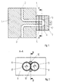
- reference numeral 1 is a spinning block designated. One does not run in the spinning block 1 with one shown extruder connected channel 2 and one with a not shown spinneret connected channel 3. With the Spinning block 1 is the spinning pump via a Pump protection plate 4 firmly connected.
- the essential Parts consist of a front plate 5 and one Middle plate 6.
- the end against an engine M forms a back plate 7.
- the back plate 7 closes in the Usually a base plate.
- Fig. 2 shows a section A-A of FIG. 1 through the front part of the middle plate 6 of a gear pump.
- the gears are designated 8.8 '. They are in Bores 9,9 'arranged.
- a hole 10 with Partial circular cross section is with channel 2 connected and a bore 10 'with the channel 3rd connected.
- the diameters of channels 2 and 3 are the same like the diameter of the holes 10, 10 'of the middle plate 6 to the front plate 5.
- the running direction of the gears is indicated by arrows.
- Fig. 3 the middle plate is shown in profile. Of the Section shows a front 6 'and a back 6 " the middle plate 6. On the front 6 'are the cylindrical bores 9 and 9 'for receiving the Gears 8,8 'shown. An edge 12a and an edge 12b of the bore 10 collide at a point 11; the edges 12a 'and 12b' of the bore 10 'meet in one Point 11 'together.
- Fig. 4 is a section B-B of Fig. 2. From the Front 6 'of the middle plate 6 run an edge 13, and an edge 13 'and meet at point 11' together. The lines 13a, 13a 'describe the profiles of the center points.
- a melt is used Extruder pressure pressed through the channel 2 of the bore 10. Due to the opposite rotation of the gears 8 and 8 ' the melt from the bore 10 into the bore 10 ' promoted. From the bore 10 'the melt is with increased pressure through channel 3 of a not shown Spinneret fed.
- the spinning pump according to the invention enables one Dead zone-free funding and an increase in productivity by more than 10%. Deposits of cracked PA 6.6 are practically prevented.
Landscapes
- Engineering & Computer Science (AREA)
- Mechanical Engineering (AREA)
- General Engineering & Computer Science (AREA)
- Extrusion Moulding Of Plastics Or The Like (AREA)
- Spinning Methods And Devices For Manufacturing Artificial Fibers (AREA)
- Rotary Pumps (AREA)
Description
- Fig. 1
- einen Schnitt einer Spinnpumpe mit einem Pumpenblock.
- Fig. 2
- eine schematische Ansicht A-A auf die Vorderseite der Mittelplatte im Bereich Polymereintritt- und Austritt.
- Fig. 3
- eine perspektivische Darstellung der Mittelplatte.
- Fig. 4
- einen Schnitt B-B durch die Mittelplatte mit den erfindungsgemässen Bohrungen.
- Fig. 5
- eine schematische Darstellung der erfindungsgemässen Bohrungen.
Claims (5)
- Spinnpumpe zum Schmelzspinnen von Polyamiden, bestehend aus einer Vorderplatte (5), einer Rückplatte (7), einer Mittelplatte (6) mit einer Bohrung (10) mit teilkreisförmigem Querschnitt für die Zufuhr der Schmelze und einer Bohrung (10') mit teilkreisförmigem Querschnitt für die Abfuhr der Schmelze, sowie einem Paar Zahnräder (8,8'), dadurch gekennzeichnet, dass die Bohrungen (10,10') mit den teilkreisförmigem Querschnitten auf der Vorderseite (6') der Mittelplatte (6) so ausgebildet sind, dass die freie Querschnittsfläche der Bohrungen (10,10') gegen die Rückseite (6") der Mittelplatte (6) verkleinert ist und die Mittelpunkte der teilkreisförmigen Bohrungen, in beiden Fällen, gegen die Rückseite (6") der Mittelplatte (6) einem parabelförmigen Profil 13a folgen.
- Spinnpumpe nach Anspruch 1, dadurch gekennzeichnet, dass das Profil 13a der Bohrungen (10,10') in beiden Fällen über die gesamte Länge stetig und nicht linear und deren erste Ableitung stetig ist.
- Spinnpumpe nach Anspruch 1, dadurch gekennzeichnet, dass der Übergang der Bohrungen (10,10') von der Vorderseite (6') der Mittelplatte (6) zur Rückplatte (5) stufenlos und knickfrei ist.
- Spinnpumpe nach Anspruch 1, dadurch gekennzeichnet, dass das Profil der Teilkreismittelpunkte der Bohrungen (10,10') auf der Rückseite (6") der Mittelplatte (6) endet und dass die Teilkreisflächen auf der Rückseite (6") der Mittelplatte (6) Null werden.
- Spinnpumpe nach Anspruch 1, dadurch gekennzeichnet, dass der Radius (r) der Bohrungen (10, 10') über die gesamte Länge der Mittelplatte (6) konstant ist.
Applications Claiming Priority (3)
| Application Number | Priority Date | Filing Date | Title |
|---|---|---|---|
| CH427/94 | 1994-02-14 | ||
| CH42794 | 1994-02-14 | ||
| PCT/CH1995/000029 WO1995022002A1 (de) | 1994-02-14 | 1995-02-07 | Spinnpumpe für polyamide |
Publications (2)
| Publication Number | Publication Date |
|---|---|
| EP0694126A1 EP0694126A1 (de) | 1996-01-31 |
| EP0694126B1 true EP0694126B1 (de) | 1998-06-03 |
Family
ID=4186779
Family Applications (1)
| Application Number | Title | Priority Date | Filing Date |
|---|---|---|---|
| EP95906876A Expired - Lifetime EP0694126B1 (de) | 1994-02-14 | 1995-02-07 | Spinnpumpe für polyamide |
Country Status (7)
| Country | Link |
|---|---|
| US (1) | US5618172A (de) |
| EP (1) | EP0694126B1 (de) |
| JP (1) | JP2961119B2 (de) |
| CN (1) | CN1062645C (de) |
| DE (1) | DE59502392D1 (de) |
| ES (1) | ES2121344T3 (de) |
| WO (1) | WO1995022002A1 (de) |
Families Citing this family (2)
| Publication number | Priority date | Publication date | Assignee | Title |
|---|---|---|---|---|
| HK1040543B (en) * | 1998-10-01 | 2004-01-21 | The Dow Chemical Company | Gear pump for pumping highly viscous fluids |
| DE102009029522A1 (de) * | 2009-09-17 | 2011-03-24 | Robert Bosch Gmbh | Zahnradpumpe mit zwei rotierenden Pumpelementen |
Family Cites Families (8)
| Publication number | Priority date | Publication date | Assignee | Title |
|---|---|---|---|---|
| DE518993C (de) * | 1931-02-21 | Barmag Barmer Maschf | Einrichtung zum Druckausgleich fuer Kunstseide-Spinnpumpen | |
| US2460649A (en) * | 1942-03-07 | 1949-02-01 | Geza W Muiler | Gear pump with flow cushioning means |
| FR948868A (fr) * | 1947-06-24 | 1949-08-12 | Perfectionnement aux pompes à engrenages | |
| DE1553125A1 (de) * | 1965-02-20 | 1970-04-30 | Maschf Augsburg Nuernberg Ag | Zahnradpumpe |
| US3817668A (en) * | 1969-05-28 | 1974-06-18 | K Mayer | Gear wheel pump with feed passage of constant hydraulic cross section |
| GB2169350B (en) * | 1985-01-05 | 1989-06-21 | Hepworth Plastics Ltd | Gear pumps |
| JP2552857B2 (ja) * | 1987-04-06 | 1996-11-13 | カヤバ工業株式会社 | ギヤポンプ |
| DE4007858C1 (en) * | 1990-03-13 | 1991-08-14 | Rhone-Poulenc Rhodia Ag, 7800 Freiburg, De | Rotary liquid pump - has pump coupled to block by symmetrically placed fastening screws |
-
1995
- 1995-02-07 EP EP95906876A patent/EP0694126B1/de not_active Expired - Lifetime
- 1995-02-07 JP JP7520884A patent/JP2961119B2/ja not_active Expired - Fee Related
- 1995-02-07 ES ES95906876T patent/ES2121344T3/es not_active Expired - Lifetime
- 1995-02-07 DE DE59502392T patent/DE59502392D1/de not_active Expired - Fee Related
- 1995-02-07 CN CN95190087A patent/CN1062645C/zh not_active Expired - Fee Related
- 1995-02-07 WO PCT/CH1995/000029 patent/WO1995022002A1/de not_active Ceased
- 1995-02-07 US US08/532,556 patent/US5618172A/en not_active Expired - Lifetime
Also Published As
| Publication number | Publication date |
|---|---|
| ES2121344T3 (es) | 1998-11-16 |
| DE59502392D1 (de) | 1998-07-09 |
| JPH08510529A (ja) | 1996-11-05 |
| CN1123049A (zh) | 1996-05-22 |
| JP2961119B2 (ja) | 1999-10-12 |
| EP0694126A1 (de) | 1996-01-31 |
| US5618172A (en) | 1997-04-08 |
| CN1062645C (zh) | 2001-02-28 |
| WO1995022002A1 (de) | 1995-08-17 |
Similar Documents
| Publication | Publication Date | Title |
|---|---|---|
| DE2536000C2 (de) | Vorrichtung zum Anschluss eines T-Abzweigs an Kunststoffrohren | |
| DE602004013223T2 (de) | Zahnrad für eine Kette | |
| DE3426671C2 (de) | ||
| DE69301410T2 (de) | Querelement für einen Treibriemen | |
| DE2446421C3 (de) | Spritzkopf zum Strangpressen von Hohlprofilen aus Kunststoff | |
| DE3435564A1 (de) | Schlauchhalter | |
| DE2720122C2 (de) | Strangpresse zum Herstellen von Profilen aus draht- oder Stangenförmigem Ausgangsprofil | |
| EP2956681B1 (de) | Zweistahlschraube mit fliesspressverbindung und verfahren zur herstellung solcher schraube | |
| DE3314718A1 (de) | Tiefbohrwerkzeug und verfahren zu seiner herstellung | |
| EP0694126A1 (de) | Spinnpumpe für polyamide | |
| DE69415558T2 (de) | Zange | |
| DE8705276U1 (de) | Rohrverbindung | |
| EP0155227B1 (de) | Reifenkette | |
| EP1664535A1 (de) | Peristaltikpumpe | |
| DE3141928C2 (de) | Bewehrungsstab für Stahlbeton | |
| WO2014127959A1 (de) | Vorrichtung zur herstellung von kunststoffrohren | |
| WO2014127958A1 (de) | Vorrichtung zur herstellung von kunststoffrohren | |
| DE1660398A1 (de) | Verfahren und Vorrichtung zum Verspinnen von synthetischen faserbildenden Polymeren | |
| DE10128700A1 (de) | Klemmring zum axialen Verbinden von zylindrischen Bauteilen | |
| DE202015005582U1 (de) | Reinigungsdüse | |
| DE3433269A1 (de) | Stator fuer exzenterschneckenpumpen | |
| DE2532977C3 (de) | Verfahren zum Verbinden elektrischer Leiter sowie Vorrichtung zum Durchführen des Verfahrens | |
| DE60201452T2 (de) | Förderkette, insbesondere für Hängeförderer und insbesondere in Schlachthöfen | |
| DE10312692B4 (de) | Rollenhalterung, insbesondere für Andrück-und Führungsrollen für Ummantelungsmaschinen | |
| DE3827677C2 (de) | Abreißgerät für Hopfenreben |
Legal Events
| Date | Code | Title | Description |
|---|---|---|---|
| PUAI | Public reference made under article 153(3) epc to a published international application that has entered the european phase |
Free format text: ORIGINAL CODE: 0009012 |
|
| AK | Designated contracting states |
Kind code of ref document: A1 Designated state(s): CH DE ES FR GB IT LI SE |
|
| 17P | Request for examination filed |
Effective date: 19951005 |
|
| 17Q | First examination report despatched |
Effective date: 19961209 |
|
| GRAG | Despatch of communication of intention to grant |
Free format text: ORIGINAL CODE: EPIDOS AGRA |
|
| RAP1 | Party data changed (applicant data changed or rights of an application transferred) |
Owner name: RHONE-POULENC FILTEC AG |
|
| GRAG | Despatch of communication of intention to grant |
Free format text: ORIGINAL CODE: EPIDOS AGRA |
|
| GRAH | Despatch of communication of intention to grant a patent |
Free format text: ORIGINAL CODE: EPIDOS IGRA |
|
| GRAH | Despatch of communication of intention to grant a patent |
Free format text: ORIGINAL CODE: EPIDOS IGRA |
|
| GRAA | (expected) grant |
Free format text: ORIGINAL CODE: 0009210 |
|
| AK | Designated contracting states |
Kind code of ref document: B1 Designated state(s): CH DE ES FR GB IT LI SE |
|
| REG | Reference to a national code |
Ref country code: CH Ref legal event code: EP |
|
| REF | Corresponds to: |
Ref document number: 59502392 Country of ref document: DE Date of ref document: 19980709 |
|
| ITF | It: translation for a ep patent filed | ||
| ET | Fr: translation filed | ||
| GBT | Gb: translation of ep patent filed (gb section 77(6)(a)/1977) |
Effective date: 19980917 |
|
| REG | Reference to a national code |
Ref country code: CH Ref legal event code: PFA Free format text: RHONE-POULENC FILTEC AG TRANSFER- RHODIA FILTEC AG |
|
| REG | Reference to a national code |
Ref country code: ES Ref legal event code: FG2A Ref document number: 2121344 Country of ref document: ES Kind code of ref document: T3 |
|
| REG | Reference to a national code |
Ref country code: ES Ref legal event code: PC2A |
|
| PLBE | No opposition filed within time limit |
Free format text: ORIGINAL CODE: 0009261 |
|
| STAA | Information on the status of an ep patent application or granted ep patent |
Free format text: STATUS: NO OPPOSITION FILED WITHIN TIME LIMIT |
|
| 26N | No opposition filed | ||
| REG | Reference to a national code |
Ref country code: GB Ref legal event code: IF02 |
|
| PGFP | Annual fee paid to national office [announced via postgrant information from national office to epo] |
Ref country code: DE Payment date: 20090206 Year of fee payment: 15 |
|
| PGFP | Annual fee paid to national office [announced via postgrant information from national office to epo] |
Ref country code: CH Payment date: 20090213 Year of fee payment: 15 |
|
| PGFP | Annual fee paid to national office [announced via postgrant information from national office to epo] |
Ref country code: IT Payment date: 20090217 Year of fee payment: 15 |
|
| PGFP | Annual fee paid to national office [announced via postgrant information from national office to epo] |
Ref country code: FR Payment date: 20090213 Year of fee payment: 15 |
|
| PGFP | Annual fee paid to national office [announced via postgrant information from national office to epo] |
Ref country code: ES Payment date: 20100329 Year of fee payment: 16 |
|
| PGFP | Annual fee paid to national office [announced via postgrant information from national office to epo] |
Ref country code: GB Payment date: 20100329 Year of fee payment: 16 |
|
| REG | Reference to a national code |
Ref country code: CH Ref legal event code: PL |
|
| PG25 | Lapsed in a contracting state [announced via postgrant information from national office to epo] |
Ref country code: LI Free format text: LAPSE BECAUSE OF NON-PAYMENT OF DUE FEES Effective date: 20100228 Ref country code: CH Free format text: LAPSE BECAUSE OF NON-PAYMENT OF DUE FEES Effective date: 20100228 |
|
| REG | Reference to a national code |
Ref country code: FR Ref legal event code: ST Effective date: 20101029 |
|
| PGFP | Annual fee paid to national office [announced via postgrant information from national office to epo] |
Ref country code: SE Payment date: 20100409 Year of fee payment: 16 |
|
| PG25 | Lapsed in a contracting state [announced via postgrant information from national office to epo] |
Ref country code: FR Free format text: LAPSE BECAUSE OF NON-PAYMENT OF DUE FEES Effective date: 20100301 |
|
| PG25 | Lapsed in a contracting state [announced via postgrant information from national office to epo] |
Ref country code: DE Free format text: LAPSE BECAUSE OF NON-PAYMENT OF DUE FEES Effective date: 20100901 |
|
| PG25 | Lapsed in a contracting state [announced via postgrant information from national office to epo] |
Ref country code: IT Free format text: LAPSE BECAUSE OF NON-PAYMENT OF DUE FEES Effective date: 20100207 |
|
| REG | Reference to a national code |
Ref country code: SE Ref legal event code: EUG |
|
| GBPC | Gb: european patent ceased through non-payment of renewal fee |
Effective date: 20110207 |
|
| PG25 | Lapsed in a contracting state [announced via postgrant information from national office to epo] |
Ref country code: GB Free format text: LAPSE BECAUSE OF NON-PAYMENT OF DUE FEES Effective date: 20110207 |
|
| REG | Reference to a national code |
Ref country code: ES Ref legal event code: FD2A Effective date: 20120411 |
|
| PG25 | Lapsed in a contracting state [announced via postgrant information from national office to epo] |
Ref country code: ES Free format text: LAPSE BECAUSE OF NON-PAYMENT OF DUE FEES Effective date: 20110208 |
|
| PG25 | Lapsed in a contracting state [announced via postgrant information from national office to epo] |
Ref country code: SE Free format text: LAPSE BECAUSE OF NON-PAYMENT OF DUE FEES Effective date: 20110208 |