EP0693176B1 - Verfahren und vorrichtung zur erfassung und analyse von fehlern an lagern und anderen gleitend rotierenden komponenten - Google Patents
Verfahren und vorrichtung zur erfassung und analyse von fehlern an lagern und anderen gleitend rotierenden komponenten Download PDFInfo
- Publication number
- EP0693176B1 EP0693176B1 EP94914066A EP94914066A EP0693176B1 EP 0693176 B1 EP0693176 B1 EP 0693176B1 EP 94914066 A EP94914066 A EP 94914066A EP 94914066 A EP94914066 A EP 94914066A EP 0693176 B1 EP0693176 B1 EP 0693176B1
- Authority
- EP
- European Patent Office
- Prior art keywords
- signal
- component
- data records
- machine
- components
- Prior art date
- Legal status (The legal status is an assumption and is not a legal conclusion. Google has not performed a legal analysis and makes no representation as to the accuracy of the status listed.)
- Expired - Lifetime
Links
- 238000000034 method Methods 0.000 title claims description 47
- 238000001228 spectrum Methods 0.000 claims description 19
- 230000001143 conditioned effect Effects 0.000 claims description 12
- 238000005096 rolling process Methods 0.000 claims description 10
- 230000001360 synchronised effect Effects 0.000 claims description 10
- 230000003750 conditioning effect Effects 0.000 claims description 9
- 238000004458 analytical method Methods 0.000 claims description 8
- 230000003993 interaction Effects 0.000 claims description 7
- 238000001914 filtration Methods 0.000 claims description 5
- 230000009466 transformation Effects 0.000 claims description 4
- 125000004122 cyclic group Chemical group 0.000 claims 2
- 230000002708 enhancing effect Effects 0.000 claims 1
- 230000003595 spectral effect Effects 0.000 description 33
- 230000007547 defect Effects 0.000 description 15
- 238000012935 Averaging Methods 0.000 description 6
- 238000005070 sampling Methods 0.000 description 6
- 238000012545 processing Methods 0.000 description 5
- 238000003672 processing method Methods 0.000 description 4
- 230000015556 catabolic process Effects 0.000 description 3
- 230000001427 coherent effect Effects 0.000 description 3
- 230000002950 deficient Effects 0.000 description 3
- 238000001514 detection method Methods 0.000 description 3
- 230000035945 sensitivity Effects 0.000 description 3
- 238000013459 approach Methods 0.000 description 2
- 238000010586 diagram Methods 0.000 description 2
- 230000033001 locomotion Effects 0.000 description 2
- 238000012423 maintenance Methods 0.000 description 2
- 238000012544 monitoring process Methods 0.000 description 2
- 230000008569 process Effects 0.000 description 2
- 206010035148 Plague Diseases 0.000 description 1
- 241000607479 Yersinia pestis Species 0.000 description 1
- 230000006978 adaptation Effects 0.000 description 1
- 230000002411 adverse Effects 0.000 description 1
- 230000000712 assembly Effects 0.000 description 1
- 238000000429 assembly Methods 0.000 description 1
- 230000008901 benefit Effects 0.000 description 1
- 238000004364 calculation method Methods 0.000 description 1
- 230000007423 decrease Effects 0.000 description 1
- 230000003247 decreasing effect Effects 0.000 description 1
- 238000006073 displacement reaction Methods 0.000 description 1
- 230000005672 electromagnetic field Effects 0.000 description 1
- 239000012530 fluid Substances 0.000 description 1
- 230000006698 induction Effects 0.000 description 1
- 230000002452 interceptive effect Effects 0.000 description 1
- 230000001788 irregular Effects 0.000 description 1
- 238000012986 modification Methods 0.000 description 1
- 230000004048 modification Effects 0.000 description 1
- 230000003287 optical effect Effects 0.000 description 1
- 230000002093 peripheral effect Effects 0.000 description 1
- 230000002688 persistence Effects 0.000 description 1
- 238000012552 review Methods 0.000 description 1
- 230000035939 shock Effects 0.000 description 1
- 238000010183 spectrum analysis Methods 0.000 description 1
Images


Classifications
-
- G—PHYSICS
- G01—MEASURING; TESTING
- G01M—TESTING STATIC OR DYNAMIC BALANCE OF MACHINES OR STRUCTURES; TESTING OF STRUCTURES OR APPARATUS, NOT OTHERWISE PROVIDED FOR
- G01M13/00—Testing of machine parts
- G01M13/02—Gearings; Transmission mechanisms
- G01M13/028—Acoustic or vibration analysis
-
- F—MECHANICAL ENGINEERING; LIGHTING; HEATING; WEAPONS; BLASTING
- F16—ENGINEERING ELEMENTS AND UNITS; GENERAL MEASURES FOR PRODUCING AND MAINTAINING EFFECTIVE FUNCTIONING OF MACHINES OR INSTALLATIONS; THERMAL INSULATION IN GENERAL
- F16C—SHAFTS; FLEXIBLE SHAFTS; ELEMENTS OR CRANKSHAFT MECHANISMS; ROTARY BODIES OTHER THAN GEARING ELEMENTS; BEARINGS
- F16C19/00—Bearings with rolling contact, for exclusively rotary movement
- F16C19/52—Bearings with rolling contact, for exclusively rotary movement with devices affected by abnormal or undesired conditions
- F16C19/527—Bearings with rolling contact, for exclusively rotary movement with devices affected by abnormal or undesired conditions related to vibration and noise
-
- G—PHYSICS
- G01—MEASURING; TESTING
- G01H—MEASUREMENT OF MECHANICAL VIBRATIONS OR ULTRASONIC, SONIC OR INFRASONIC WAVES
- G01H1/00—Measuring characteristics of vibrations in solids by using direct conduction to the detector
- G01H1/003—Measuring characteristics of vibrations in solids by using direct conduction to the detector of rotating machines
-
- G—PHYSICS
- G01—MEASURING; TESTING
- G01M—TESTING STATIC OR DYNAMIC BALANCE OF MACHINES OR STRUCTURES; TESTING OF STRUCTURES OR APPARATUS, NOT OTHERWISE PROVIDED FOR
- G01M13/00—Testing of machine parts
- G01M13/04—Bearings
- G01M13/045—Acoustic or vibration analysis
Definitions
- This invention relates to a signal processing method and apparatus for detecting faults and other features of rotating components that slip in rotating machinery.
- it relates to a method and apparatus that employs shaft encoders to average synchronously and to isolate signals arising from these asynchronously rotating components.
- Rolling-element bearings are manufactured in greater numbers than any other precision machine component and their failure is the most common cause of machine breakdown.
- the ability to detect the onset of breakdown of the elements of a roller bearing, such as the onset of pitting or cracks in the bearing races or rolling elements is fundamental to practicing predictive maintenance on machinery and avoiding catastrophic machine failure.
- Roller bearings, other anti-friction bearings, belt-pulley assemblies and various other machine components are known to experience rotational slip in ordinary operation.
- the rotors of AC induction motors may also be considered to slip relative to their rotating electromagnetic fields.
- Oil whirl and oil whip can be considered as slipping shaft motions relative to the shaft rotation in journal bearings.
- Fluid circulation about the rotating shaft in a journal bearing or mechanical seal can be considered as a rotating component slipping relative to the shaft motion.
- Vibration-signal-processing methods have been used to analyze the operation of some of these slipping components.
- the presence of large spectral components at the (1) inner-race ball passing frequency, (2) outer-race ball passing frequency, (3) ball-spin frequency and (4) cage-rotation frequency, as well as the higher harmonics of each of these components tend to indicate the existence of faults in the associated bearing components.
- these signals are difficult to distinguish from background noise.
- frequency components commonly exist that correspond to modulations or sidebands between the foregoing slipping components and various shaft-rotation frequency harmonics.
- these modulations or sidebands generally have not been utilized in the spectral analysis of bearings.
- US-A-4 931 949 describes a gear defect analyzing system which corresponds approximately to the precharacterising clause of claim 1.
- FR-A-2 681 942 discloses the use of a mathematical transformation in order to obtain information about different parameters of the signal to be analyzed.
- Other background arrangements are described in US-A-3 971 249 and JP-A-2-222818.
- a signal processing method called “shaft-synchronous averaging” has been used to analyze gear vibration and detect gear faults "Low Frequency Vibration Generated by Gear Tooth Impacts", NDT International, Vol. 18, No. 5, October 1985. This method is based on the fact that gears are rigidly coupled to their associated shafts, and to each other by the intermeshing of their teeth. Because of the fixed rotational relationships of the elements in a gear machine, signals associated with their rotation, such as vibration, can be averaged synchronously, i.e. by superposition of the signals in fixed relationship to the angular orientation of one element of the assembly, such as a gear-driven shaft.
- this synchronous-averaging gear method produces spectra reflecting only those vibrations synchronous with gear rotation, and not such asynchronous vibrations as from bearings and other components that slip.
- the simple subtraction of consecutive data records before signal conditioning and processing eliminates most of the synchronous signals, such as shaft harmonics.
- all gear mesh and shaft generated signals can be eliminated by subtracting data records that are separated by an integer multiple of the hunting tooth cycle, the hunting tooth cycle being defined as the time required for all gears and shafts of interest to rotate to their initial angular orientation.
- the invention comprises a method and apparatus for detecting faults in slipping machine components, e.g. rolling-element bearings, by synchronously averaging and further processing asynchronous signals emanating from machines.
- the method processes signals from a sensor, e.g. an accelerometer fixed or focused on a machine of interest, and from an encoder detecting the rotation of a component of the machine.
- the sensor and encoder signals are sent through interface circuits to, respectively, an analog signal conditioner and an encoder pulse-multiplier.
- the encoder pulse train is multiplied or divided to produce a new pulse train with a fixed number of pulses per encoder rotation, consistent with the Nyquist criterion on sampling frequency.
- the sensor signal is forwarded to an analog signal conditioner that conditions and forwards the signal to a processor or computer stage.
- the computer digitizes and samples the signal, using the pulse-multiplied encoder signal as an external clock. By this, the computer generates data records of fixed length, which then are processed by the computer. Processing of the data records begins with a Discrete Fourier Transformation (DFT).
- DFT Discrete Fourier Transformation
- the components of the DFT, or its complex conjugates, then are used to calculate a new spectral function, G(I), which may be a 2-form or a higher order function of various forms.
- G(I) a new spectral function
- each element of G(I) is the product of two DFT spectral components or their complex conjugates, the sum (or difference) of whose frequencies is equal to some fixed harmonic of shaft rotation.
- G(I) is averaged over a large number of data records to produce ⁇ G(I)>.
- a 3-form would be the product of three spectral components. Higher forms would be formed accordingly.
- Certain spectral components, such as for the rolling elements, will add constructively. Background noise, however, will add destructively and tend towards zero. The result is the emergence of spectral lines associated with specific machine components that slip. These spectral lines or their relationships are used to determine the condition of the machine, and a number of its other attributes. These, in turn, are the basis for alarms or other messages generated by the computer.
- An important advantage of this invention is that it generalizes synchronous signal-averaging techniques, enabling their application to bearings and other components that slip in a manner that detects component defects even in the presence of high levels of background noise. Used in conjunction with gear monitoring techniques, this technique enables the detection of faults in complex rotating machines composed of both components that rotate synchronously and ones that slip. By utilizing higher order and other forms of G, it is possible to examine interactions between, even indirectly coupled, asynchronously rotating components, such as two bearings coupled via a meshing gear pair, a powerful tool in monitoring the complex machinery being introduced in advanced applications.
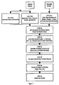
- Figure 1 is a block diagram of the preferred embodiment of the present invention.
- Figure 2 is a flowchart of the steps by which the system analyzes signals for components that slip in rotating machines and detects machinery defects.
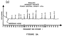
- Figure 3a is an idealized representation of a power spectrum ⁇ P(I)> illustrating where spectral lines might be expected to occur for a roller bearing with a worn rolling element, if the lines were not submerged in the background noise that traditional techniques do not suppress effectively.
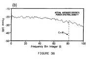
- Figure 3b is an actual power spectrum P(I) calculated for a rolling element bearing with a defective roller.
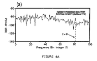
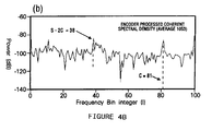
- Figures 4A-4B show an actual 2-form spectrum ⁇ G> for the roller bearing data used to form P(I) in figure 3b.
- the length of an individual data record is 200 shaft rotations.
- the number of records averaged in figure 4a is 112 records.
- the number of records averaged is 1053. Sensitivity is proportional to the square root of record number.
- Figure 5 is an idealized example of the averaged spectral function ⁇ G> where we have chosen the form F(100-K)F(K).
- the data record length is equal to 100 turns of the shaft, and J and L are set to 100 and 0 respectively. Averaged over many records, the background noise will tend to zero and the cage lines to converge on finite values, making them readily detectable.
- Figure 6 is an idealized example of the averaged spectral function ⁇ G> where we have chosen the form F(200K)F(100+K) and the data record length equal to 100 turns of the shaft. With this form more spectral peaks occur, some of which have been omitted here for clarity.
- Figure 7 is an idealized example of an averaged power spectral density function ⁇ P> for a rolling element bearing with a defective outer race. Spectral components are present at the outer-race ball passing frequency F 0 and shaft modulation components about the ball passing frequency at frequencies F 0 ⁇ S.
- FIG. 1 The invention according to the preferred embodiment is illustrated in Figure 1 by a block diagram.
- An accelerometer 2 senses vibration produced by a rotating machine.
- a shaft encoder 4 produces H' pulses per revolution of a machine component such as a shaft (hereafter referred to as a shaft). These signals are passed to the interface 6.
- Pulse multiplier electronics 8 increases or decreases the pulse rate to provide H pulses per shaft rotation which are sent to the computer 12.
- Analog electronics 10 provide signal conditioning for the accelerometer signal.
- the computer 12 receives these signals, processes and analyzes them, and communicates to peripherals, such as an RS-232 link 14, a CRT 16, a printer 20 or a keyboard 22.
- the computer contains an analog-to-digital processor 18 that converts the conditioned accelerometer signal to digital form.
- the external clock controlling the digitizer is provided by the encoder pulses.
- the first step in the preferred method comprises the detection and conditioning of the sensor and encoder signals.
- the sensor 2 that detects the vibration signal is an off-the-shelf, wideband piezoelectric accelerometer with a frequency range from the lowest frequencies of interest to 50 KHz or more.
- the sensor signal may be conditioned in several ways, two of which are illustrated in figure here.
- step 1A the signal is low-pass filtered (for anti-aliasing) and amplified for sufficient dynamic range before being digitized.
- filtering solely by low pass is considered to produce baseband data.
- a particular frequency band of interest e.g. the band 30-50 KHz
- filtering by bandpass shall be considered to produce bandpassed or high frequency data.
- the encoder signal is provided by shaft encoder 4 which may consist of a mounted gear or other energy reflecting surface and a magnetic, optical or other pickup producing a pulse per increment of shaft rotation. For example, a gear with 60 teeth would produce pulses 6 degrees apart.
- the pulse rate may be multiplied or divided to provide H pulses per turn of the shaft, satisfying the Nyquist criterion on signal sampling rate.
- step 2 the conditioned vibration-sensor signal from either step 1A or 1B is digitized by an analog-to-digital converter 18 with the clock controlling sampling rate being provided by the pulses from step lC.
- the clock controlling sampling rate being provided by the pulses from step lC.
- step 3 the computer captures N samples of data to form a data record.
- the first sample in each record is taken such that it occurs at a fixed angular position of the shaft.
- a complex DFT, (FI) is calculated for the data record.
- the length of the data record determines the resolution of the spectrum. For example, for a record equivalent to 100 shaft turns and a shaft rotation rate of 30 Hz, the resolution is 30/100 Hz, or 0.3 Hz.
- S shaft rotation rate
- this technique is referred to as Order Analysis, with shaft orders (or harmonics) located at frequency bins T, 2T, 3T, etc.
- a new discrete spectral function G(J,K/L) is calculated.
- This function may take various forms depending on the application. Examples include F(J-K)F(L+K) and F(J-K)F*(K-L), where F* represents the complex conjugate.
- K is a positive integer less than J, representing the discrete frequencies, or bin values, for which G is formed.
- J and L are shaft-order bin values.
- the spectral function can take a number of forms, such as, for a shaft frequency of 100; F(K)F(100-K), F(100+K)F(100-K), F(K)F(200-K), F(200+k)F(200-K), F(K)F(300-K), F(100+K)F(200-K), F(K)F(400-K), F(200+K)F(300-K), F(K-100)F*(K+100), F(K-100)F*(K+200)
- the product of the two spectral components produces two new spectral components with frequencies equal to the sum and difference respectively of the original components.
- the sum of the frequency components of each of the forms is equal to an integer multiple of T, the first shaft harmonic bin, i.e. 100, 200 or 300. Critical to the method, these summed components are synchronous with the shaft rotation and can be synchronously added and averaged.
- the spectral function G formed in this manner is averaged over M, typically a large number of, data records to produce the averaged function ⁇ G>.
- Frequency components of G corresponding to cage rotation frequency, C, or its harmonics, 2C, 3C, etc., and other synchronously related components, will have fixed phases relative to each other and will add constructively, whereas other components that are not of fixed phase relations will add destructively and tend towards zero.
- ⁇ G> is automatically examined for extrema in spectral bin regions where component lines are expected. For example, bearing cage lines typically occur at bins between .35 and .45 times the first shaft-order bin number. Extrema so detected are used to calculate the condition of the various components of interest.
- Figure 3a is an idealized representation of a power spectrum ⁇ P(I)> for a roller bearing with a worn rolling element, illustrating where spectral lines would appear, if they were not submerged in the background noise that plagues traditional spectral techniques.
- the data record length is 100 shaft turns.
- Spectral components at the bins representing the first and second shaft harmonics, 2S and 3S, the first, second and third harmonics of the cage frequencies, C, 2C and 3C, and various inter-modulations, S-2C, S-C, 2S-3C etc., are present. While shaft harmonics fall exactly on integer bins values, owing to the nature of the analysis, other components, such as C or S-2C, typically will not.
- the spectral energies of these components will tend to "leak over" into adjacent bins and appear as slightly broadened spectral components.
- inter-modulation lines at bins S-2C, 2S-3C etc. are caused by non-linear interactions between the bearing cage and the shaft.
- the result is that the amplitudes and phases of these inter-modulation spectral components are, for a given fixed bearing condition, directly determined by the amplitudes and phases of the bearing cage and shaft spectral components.
- Figure 3b is an actual power spectrum ⁇ P(I)> calculated for a for a rolling element bearing with a rolling element defect, which can also be considered a cage defect since the rolling element moves with the cage.
- Figures 4A-4B show examples of an actual 2-form spectrum ⁇ G> calculated with the data used to form ⁇ P(I)> in figure 3b.
- Record length is 200 shaft turns.
- ⁇ G(I)> is averaged over 112 records in 4a and 1053 records in 4b.
- a peak is beginning to emerge at bin 81.
- the line at bin 81 is clearly the cage line.
- a line is also emerging at bin 38, or S-2C.
- G may also be calculated in higher order forms, for example for application to machines with more complex interactions.
- Figures 5 and 6 show idealized averaged functions, ⁇ G>, that might be expected for a bearing with an irregular or damaged roller, or damaged cage.
- data record length is 100 shaft turns.
- step 7 of the method a decision is made regarding the relationship of the features or measures generated in step 6 to certain pre-set criteria. As appropriate, an alarm or other message is generated by the computer 12. Such analyses may include review of historical trends in the features or measures generated in steps 1-6.
- the senor can be any device that detects signals generated by the bearing or other component of interest. Examples include: displacement or velocity sensors, microphones, or acoustic emission sensors.
- the number of samples per shaft rotation, H need not be an integer number. It is sufficient that it be a fixed number. This approach may be convenient when analyzing gearboxes since the encoder may supply an integral number of pulses for a given shaft but, in general, not for other shafts in the gear train. For example, take the meshing of an 11 tooth gear with a 30 tooth gear, with an encoder sensing H pulses per turn of the shaft bearing the 11 tooth gear. For the shaft carrying the 30 tooth gear, the number of pulses per turn is 30H/11, which may not be an integer. The analysis is indifferent to the number of pulses, so long as the data records are a fixed multiple of shaft rotations.
- step 3 it is desirable, but not required to use a data record length corresponding to an integral number of shaft turns. If records of another length are chosen, the shaft spectral lines may not fall exactly on spectral bins. In this case, when calculating G, bin values for J and L should be chosen close to shaft harmonic orders. While this approach sacrifices some sensitivity, it may be desirable when the need to generate FFT-type spectra restricts records to an integral power of two data points in length.
- each data record is not imperative to begin at the same angular orientation of the shaft or to employ an encoder to control digitizing.
- shaft spectral lines may be used to calculate a pulse train as an external clock for digitizing and sampling the signal.
- the methods described above focus on detecting cage or roller-related problems in roller bearings.
- the method of this invention can also be used to detect race-related problems in bearings.
- Outer-race and inner-race defects tend to produce vibrations at mC and m(S-C) respectively, where m is the number of roller elements.
- the sum of mC and m(S-C) is equal to mS, which is synchronous with shaft rotation and generates a spectral line in G or ⁇ G> at bin mS.
- outer race defects may be detected in the enveloped high frequency data with a standard cross-spectral coherent calculation between the two signals and searching for a line peak in the region of bin mC. This is because both high and low frequency components are produced by the outer race and, therefore, coherent with each other.
- shaft frequency sidebands typically appear symmetrically about the defect frequency F 0 .
- Figure 7 demonstrates a means to exploit this in detecting defects.
- the shaft frequency, S is 25 Hz.
- the functional form of G is therefore F(K-25)F*(K+25).
- Defective bearings also often produce an audible ringing at a resonance frequency, F R , which is modulated at the shaft rotation.
- F R resonance frequency
- G can be generalized to the form F(J-L)F(L+K)F'*(J+L), where F'* is the complex conjugate of the encoder signal complex spectrum. This generalized function G is averaged as previously over a sufficient number of data records of fixed length but arbitrary starting point with respect to shaft angular orientation.
- the number of rollers in a bearing can also be calculated, using the form F(S)F(mS-K), where m is the number of rollers.
- the value of m generating the maximum value of G when K equals the outer-race ball-passing frequency represents the number of rollers in the bearing.
Landscapes
- Physics & Mathematics (AREA)
- General Physics & Mathematics (AREA)
- Engineering & Computer Science (AREA)
- General Engineering & Computer Science (AREA)
- Acoustics & Sound (AREA)
- Mechanical Engineering (AREA)
- Testing Of Devices, Machine Parts, Or Other Structures Thereof (AREA)
- Measurement Of Mechanical Vibrations Or Ultrasonic Waves (AREA)
Claims (18)
- Verfahren zur Analyse einer arbeitenden umlaufenden Maschine mit wechselwirkenden Bauteilen, wobei die wechselwirkenden Bauteile mindestens ein erstes, sich relativ zu einem zweiten Bauteil asynchron drehendes Bauteil, wobei das erste Bauteil ein Asynchronbauteil und das zweite Bauteil ein Synchronbauteil ist, umfassen, mit folgenden Schritten:gekennzeichnet durch das Bilden einer Spektralfunktion G durch Multiplizieren von Paaren von Komponenten der DFT bzw. der komplex Konjugierten der DFT, um multiplizierte Paare zu erzeugen, so daß die Summe bzw. Differenz der jeweiligen Frequenzen von jedem der multiplizierten Paare eine Konstante und etwa gleich einer spezifischen Harmonischen der Rotationsfrequenz des zweiten Bauteils ist;a. Erfassen eines Maschinensignals von der umlaufenden Maschine, wobei das Maschinensignal mehrere von den wechselwirkenden Bauteilen erzeugte Wechselwirkungselemente aufweist,b. Aufbereiten des Maschinensignals, um ein aufbereitetes Signal zu erzeugen,c. Digitalisieren des aufbereiteten Signals, um pro Umdrehung des zweiten Bauteils eine feste Anzahl von digitalisierten Abtastwerten zu erzeugen;d. Erfassen von Datensätzen fester Länge, wobei die Sätze aus einer konstanten Anzahl der digitalisierten Abtastwerte bestehen, in denen der erste digitalisierte Abtastwert jedes der Datensätze fester Länge bei einer festen Winkelorientierung des zweiten Bauteils auftritt,e. Durchführen einer Analyse der Datensätze durch diskrete Fourier-Transformation (DFT);Summieren der multiplizierten Paare über mehrere M der Datensätze und Dividieren durch M, um einen Durchschnitt zu bilden; undAnalysieren des Durchschnitts auf Extremwerte hin.
- Verfahren nach Anspruch 1, bei dem das Maschinensignal ein Vibrationssignal ist.
- Verfahren nach Anspruch 1 oder 2, bei dem in Schritt b die Aufbereitung die Schritte der Tiefpaßfilterung des Maschinensignals und Verstärken des gefilterten Signals zur Erzeugung eines Basisbands umfaßt.
- Verfahren nach Anspruch 1 oder 2, bei dem in Schritt b die Aufbereitung durch die Schritte der Bandpaßfilterung der Maschinensignalhüllkurve, der Erfassung des gefilterten Signals und der Verstärkung des eingehüllten Signals durchgeführt wird.
- Verfahren nach einem der Ansprüche 1 bis 4, bei dem ein Rotationssignal für das Synchronbauteil erfaßt wird.
- Verfahren nach Anspruch 5, bei dem das Rotationssignal mit Hilfe eines Drehwinkelgebers erfaßt wird.
- Verfahren nach Anspruch 5, bei dem das Rotationssignal durch Filtern eines erfaßten Signals von der umlaufenden Maschine gebildet wird, um eine spezifische Harmonische des Synchronbauteils zur Bildung des Rotationssignals zu erzeugen.
- Verfahren nach Anspruch 5, bei dem die Schritte c bis d folgende Schritte umfassen:Modifizieren des Rotationssignals, um mehrere Impulse zu bilden, wobei die mehreren Impulse eine Impulsfolge bilden,Digitalisieren des aufbereiteten Signals mit einer durch die Impulsfolge gesteuerten Geschwindigkeit, um ein digitalisiertes Signal zu erzeugen, wobei das digitalisierte Signal mehrere Digitalsignalelemente aufweist;Bilden von Folgen aus den Digitalsignalelementen mit einer festen Länge, wobei die Folgen zeitlich durch ein ganzzahliges Vielfaches der Umlaufperiode der Maschine voneinander getrennt sind;Verbessern des digitalisierten Signals durch paarweises Subtrahieren aufeinanderfolgender der Folgen, um eine Folge von verbesserten Digitalsignalelementen zu bilden;Bilden der Datensätze fester Länger durch Erfassen einer festen Anzahl der verbesserten Digitalsignalelemente, wobei jeder der Datensätze an einer festen Stelle bezüglich der Winkelorientierung des Synchronbauteils initialisiert wird.
- Verfahren nach Anspruch 5, bei dem die Schritte c bis d folgende Schritte umfassen:Digitalisieren des aufbereiteten Signals und des Rotationssignals unter der Steuerung durch einen internen Takt; undBilden der Datensätze gleicher Länge für das aufbereitete Signal und das Rotationssignal.
- Verfahren nach Anspruch 1, bei dem die Schritte c und d folgendes umfassen:Digitalisieren des aufbereiteten Signals unter der Steuerung durch einen internen Takt; undBilden der Datensätze des aufbereiteten Signals mit gleicher Länge.
- Verfahren nach einem der vorhergehenden Ansprüche, weiter mit dem Schritt des Auslösens eines Alarms mit den Attributen.
- Verfahren nach einem der vorhergehenden Ansprüche, bei dem die Frequenzsstellen gewisser der Attribute dazu verwendet werden, andere Attribute der Asynchronbauteile zu berechnen, wobei zu den Attributen Relativdurchmesser von Lagerbauteilen und die Anzahl von Elementen in einem Lager mit rollenden Elementen zählen.
- Einrichtung zum Analysieren von Signalen von einer umlaufenden bzw. rotierenden Maschine, bei dem ein erstes Bauteil der Maschine eine Rotationsfrequenz aufweist und physisch mindestens einem zweiten umlaufenden Bauteil zugeordnet ist, wobei das erste Bauteil ein Asynchronbauteil und das zweite Bauteil ein Synchronbauteil ist, wobei die Einrichtung folgendes umfaßt:gekennzeichnet durch einen Multiplizierer für das Bilden einer Spektralfunktion G durch Multiplizieren von Paaren von Komponenten der DFT bzw. der komplex Konjugierten der DFT, um multiplizierte Paare zu erzeugen, so daß die Summe bzw. Differenz der jeweiligen Frequenzen von jedem der multiplizierten Paare eine Konstante und etwa gleich einer spezifischen Harmonischen der Rotationsfrequenz des zweiten Bauteils ist; ein Mittel zum Summieren der multiplizierten Paare über mehrere M der Datensätze und Dividieren durch M, um einen Durchschnitt zu bilden;einen an die Maschine gekoppelten Sensor (2);eine an den Sensor gekoppelte Schnittstelle (6);ein an die Schnittstelle angeschlossenes Aufbereitungsmittel zum Aufbereiten des Signals von der umlaufenden bzw. rotierenden Maschine, um ein aufbereitetes Signal zu erzeugen;ein Digitalisierungsmittel zum Digitalisieren des aufbereiteten Signals;ein gepulstes Signalmittel zum Steuern des Digitalisierungsmittels, um pro Umdrehung des zweiten Bauteils eine feste Anzahl von digitalisierten Abtastwerten zu erzeugen; undein Rechnermittel zum Erfassen von Datensätzen fester Länge, wobei die Sätze aus einer konstanten Anzahl digitalisierter Abtastwerte bestehen, in denen der erste digitalisierte Abtastwert jedes der Datensätze fester Länge bei einer festen Winkelorientierung des zweiten Bauteils auftritt, und Durchführen einer Analyse der Datensätze durch diskrete Fourier-Transformation (DFT);ein Mittel zum Analysieren des Durchschnitts auf Extremwerte hin; undein Ausgabemittel zur Anzeige der Ergebnisse der Analyse.
- Einrichtung nach Anspruch 13, weiter mit einem mit der Maschine verbundenen Drehwinkelgeber, wobei der Drehwinkelgeber für jede Drehung des zweiten Bauteils eine feste Anzahl von Impulsen des Signals erzeugt; undein Impulsmultipliziermittel zum Verändern der Impulsrate von dem Geber zu einer optimierten Rate.
- Einrichtung nach Anspruch 14, bei der das Ausgabemittel aus einem CRT-Monitor besteht.
- Einrichtung nach Anspruch 15, bei der das Ausgabemittel weiterhin aus einem Alarm besteht, der anzeigt, wann die Attribute der Signale vorbestimmte Kriterien erfüllen.
- Einrichtung nach einem der Ansprüche 13 bis 16, bei der der Sensor ein Vibrationssensor ist.
- Einrichtung nach Anspruch 17, bei der das Rechnermittel dafür ausgelegt ist, an den Datensätzen fester Länge die DFT-Analyse durchzuführen, und die Paare der DFT-Komponenten multipliziert, eine DFT-Signalkomponente für eine spezifische Harmonische der komplex Konjugierten des zweiten Bauteils erhält und das multiplizierte Paar zur Bildung einer 3-Form G(I) mit der Komponente der komplex Konjugierten multipliziert, und die 3-Form G(I) über eine vorbestimmte Anzahl der Datensätze mittelt, um <G(I)> zu bilden, und die Funktion auf interessierende Attribute hin analysiert.
Applications Claiming Priority (3)
| Application Number | Priority Date | Filing Date | Title |
|---|---|---|---|
| US08/045,604 US5511422A (en) | 1993-04-09 | 1993-04-09 | Method and apparatus for analyzing and detecting faults in bearings and other rotating components that slip |
| US45604 | 1993-04-09 | ||
| PCT/US1994/003808 WO1994024537A1 (en) | 1993-04-09 | 1994-04-07 | Method and apparatus for analyzing and detecting faults in bearings and other rotating components that slip |
Publications (3)
| Publication Number | Publication Date |
|---|---|
| EP0693176A1 EP0693176A1 (de) | 1996-01-24 |
| EP0693176A4 EP0693176A4 (de) | 1997-03-05 |
| EP0693176B1 true EP0693176B1 (de) | 1999-10-27 |
Family
ID=21938877
Family Applications (1)
| Application Number | Title | Priority Date | Filing Date |
|---|---|---|---|
| EP94914066A Expired - Lifetime EP0693176B1 (de) | 1993-04-09 | 1994-04-07 | Verfahren und vorrichtung zur erfassung und analyse von fehlern an lagern und anderen gleitend rotierenden komponenten |
Country Status (6)
| Country | Link |
|---|---|
| US (1) | US5511422A (de) |
| EP (1) | EP0693176B1 (de) |
| AU (1) | AU6627894A (de) |
| CA (1) | CA2159920A1 (de) |
| DE (1) | DE69421393T2 (de) |
| WO (1) | WO1994024537A1 (de) |
Families Citing this family (84)
| Publication number | Priority date | Publication date | Assignee | Title |
|---|---|---|---|---|
| EP0673505A1 (de) * | 1992-12-08 | 1995-09-27 | Skf Condition Monitoring, Inc. | Hüllkurvenverbesserungsystem zum erfassen von anomalen schwingungsmessungen |
| NL9401949A (nl) * | 1994-11-22 | 1996-07-01 | Skf Ind Trading & Dev | Werkwijze voor het analyseren van regelmatig geëxciteerde mechanische trillingen. |
| DE19600640A1 (de) * | 1996-01-10 | 1997-07-17 | Wilo Gmbh | Sensor für eine Motorkreiselpumpe |
| US5825657A (en) * | 1996-02-23 | 1998-10-20 | Monitoring Technology Corporation | Dynamic, non-uniform clock for resampling and processing machine signals |
| DE29611558U1 (de) | 1996-07-05 | 1997-08-07 | Siemens AG, 80333 München | Vorrichtung zur Erfassung von analogen Meßsignalen für die akustische Diagnose von Prüflingen |
| US20050049801A1 (en) * | 1996-07-05 | 2005-03-03 | Stefan Lindberg | Analysis system |
| SE510771C2 (sv) | 1996-07-05 | 1999-06-21 | Spm Instr Ab | Förfarande för utvärdering av konditionen för en maskin jämte analysapparat samt anordning för samverkan med analysapparaten |
| US5922963A (en) * | 1997-06-13 | 1999-07-13 | Csi Technology, Inc. | Determining narrowband envelope alarm limit based on machine vibration spectra |
| US5875420A (en) * | 1997-06-13 | 1999-02-23 | Csi Technology, Inc. | Determining machine operating conditioning based on severity of vibration spectra deviation from an acceptable state |
| US6006164A (en) * | 1997-07-22 | 1999-12-21 | Skf Condition Monitoring, Inc. | Portable vibration monitor |
| US6202491B1 (en) | 1997-07-22 | 2001-03-20 | Skf Condition Monitoring, Inc. | Digital vibration coupling stud |
| US5992237A (en) * | 1997-07-22 | 1999-11-30 | Skf Condition Monitoring, Inc. | Digital vibration coupling stud |
| DE19806782A1 (de) * | 1998-02-18 | 1999-08-19 | Busch Dieter & Co Prueftech | Vorrichtung und Verfahren zur Analyse von Signalen |
| US6351714B1 (en) * | 1998-03-03 | 2002-02-26 | Entek Ird International Corporation | Order tracking signal sampling process |
| SE510906C2 (sv) * | 1998-04-08 | 1999-07-05 | Nils Christer Svensson | Mätutrustning innefattande två sensorer |
| WO1999054698A2 (de) * | 1998-04-17 | 1999-10-28 | Siemens Aktiengesellschaft | System und verfahren zur projektierung und durchführung von prüfabläufen |
| DE59906108D1 (de) * | 1998-04-17 | 2003-07-31 | Siemens Ag | Akustisches diagnosesystem und -verfahren |
| FI112972B (fi) * | 1998-07-15 | 2004-02-13 | Abb Research Ltd | Laakerin kunnon arviointi |
| DE19902326C2 (de) * | 1999-01-21 | 2003-05-08 | Medav Digitale Signalverarbeit | Verfahren zur Schadensfrüherkennung von rotierenden Maschinen |
| US7562135B2 (en) | 2000-05-23 | 2009-07-14 | Fisher-Rosemount Systems, Inc. | Enhanced fieldbus device alerts in a process control system |
| US6510397B1 (en) | 1999-03-13 | 2003-01-21 | Textron Systems Corporation | Method and apparatus for self-diagnosis of a sensor |
| US6546814B1 (en) | 1999-03-13 | 2003-04-15 | Textron Systems Corporation | Method and apparatus for estimating torque in rotating machinery |
| US6694285B1 (en) | 1999-03-13 | 2004-02-17 | Textron System Corporation | Method and apparatus for monitoring rotating machinery |
| US6425293B1 (en) | 1999-03-13 | 2002-07-30 | Textron Systems Corporation | Sensor plug |
| US6185995B1 (en) * | 1999-07-06 | 2001-02-13 | Abb Flexible Automation Inc. | Method and system for determining proper assembly of engine components |
| US6415189B1 (en) | 1999-07-23 | 2002-07-02 | International Business Machines Corporation | Method and system for predicting disk drive failures |
| DE19938722B4 (de) * | 1999-08-16 | 2010-10-07 | Prüftechnik Dieter Busch AG | Verfahren und Vorrichtung zur Analyse von Wälzlagern in Maschinen |
| US6868348B1 (en) * | 1999-10-29 | 2005-03-15 | Entek Ird International Corporation | Adaptive high frequency energy detection |
| WO2001088764A1 (en) * | 2000-05-16 | 2001-11-22 | Arkray, Inc. | Measurement data processing system |
| US6591682B1 (en) * | 2000-08-14 | 2003-07-15 | Pruftechnik Dieter Busch Ag | Device and process for signal analysis |
| US6378373B1 (en) | 2000-11-09 | 2002-04-30 | New Hampshire Ball Bearings, Inc. | High-speed bearing vibrational analysis system |
| DE10100522B4 (de) * | 2001-01-08 | 2013-03-28 | Deere & Company | Überwachungseinrichtung zur Überwachung der Funktion einer Arbeitsmaschine |
| US7136794B1 (en) * | 2001-05-24 | 2006-11-14 | Simmonds Precision Products, Inc. | Method and apparatus for estimating values for condition indicators |
| DE10139759A1 (de) * | 2001-08-13 | 2003-03-27 | Siemens Ag | Diagnose von Robotergetrieben |
| US7059191B2 (en) * | 2001-09-21 | 2006-06-13 | Texas Instruments Incorporated | Determining defective devices which generate sound during operation |
| DE10146895A1 (de) * | 2001-09-24 | 2003-04-24 | Siemens Ag | Auswertung des Abklingverhaltens eines Prüfobjekts |
| US6711952B2 (en) | 2001-10-05 | 2004-03-30 | General Electric Company | Method and system for monitoring bearings |
| WO2003062770A1 (en) * | 2002-01-18 | 2003-07-31 | Spm Instrument Ab | An analysis system for analysing the condition of a machine |
| DE10228389B4 (de) * | 2002-04-13 | 2006-11-09 | I-For-T Gmbh | Schwingungssensor und Verfahren zur Zustandsüberwachung von rotierenden Bauteilen und Lagern |
| US7231303B2 (en) * | 2002-04-13 | 2007-06-12 | I-For-T Gmbh | Vibration sensor and method for monitoring the condition of rotating components and bearings |
| US6775642B2 (en) | 2002-04-17 | 2004-08-10 | Motorola, Inc. | Fault detection system having audio analysis and method of using the same |
| US6915235B2 (en) * | 2003-03-13 | 2005-07-05 | Csi Technology, Inc. | Generation of data indicative of machine operational condition |
| DE10312087A1 (de) * | 2003-03-19 | 2004-10-07 | Daimlerchrysler Ag | Verfahren zur Funktionsprüfung eines Hydraulikventils und Prüfstand zur Durchführung des Verfahrens |
| US6889553B2 (en) * | 2003-07-16 | 2005-05-10 | Pcb Piezotronics Inc. | Method and apparatus for vibration sensing and analysis |
| US6925879B2 (en) * | 2003-09-30 | 2005-08-09 | Spx Corporation | Vibration analyzer and method |
| US7912659B2 (en) * | 2004-06-28 | 2011-03-22 | General Electric Company | System and method for monitoring the condition of a drive train |
| DE102004050897A1 (de) * | 2004-10-19 | 2006-05-11 | Siemens Ag | Verfahren und Einrichtung zur Erkennung eines schadhaften Lagers einer rotierend umlaufenden Welle |
| US7253020B2 (en) * | 2005-01-04 | 2007-08-07 | Omnivision Technologies, Inc | Deuterium alloy process for image sensors |
| DE102005023256A1 (de) * | 2005-05-20 | 2006-11-23 | Deere & Company, Moline | Überwachungseinrichtung und ein Verfahren zur Überwachung der Funktion der Komponenten einer landwirtschaftlichen Arbeitsmaschine |
| FR2913769B1 (fr) * | 2007-03-12 | 2009-06-05 | Snecma Sa | Procede de detection d'un endommagement d'un roulement de palier d'un moteur |
| US8185359B2 (en) * | 2008-07-03 | 2012-05-22 | Caterpillar Inc. | System and method for transforming data between the time domain and the combustion pulse domain |
| US9618037B2 (en) | 2008-08-01 | 2017-04-11 | Honeywell International Inc. | Apparatus and method for identifying health indicators for rolling element bearings |
| ES2775976T3 (es) | 2009-03-05 | 2020-07-28 | Tetra Laval Holdings & Finance | Mantenimiento predictivo de cojinetes de rodadura |
| US8958995B2 (en) | 2009-04-02 | 2015-02-17 | Honeywell International Inc. | System and method for monitoring rotating and reciprocating machinery |
| FR2952177B1 (fr) * | 2009-11-04 | 2012-06-01 | Snecma | Procede de detection d'un endommagement d'au moins un roulement de palier d'un moteur |
| EP2354786A3 (de) * | 2010-02-09 | 2013-03-06 | Fuji Jukogyo Kabushiki Kaisha | System und Verfahren zur Messung der Schadenslänge |
| SE534939C2 (sv) * | 2010-04-09 | 2012-02-21 | Leine & Linde Ab | Förfarande och anordning för att bestämma parametrar relaterade till typer av vibrationer för en avkodare monterad på en axel |
| EP2498076A1 (de) * | 2011-03-11 | 2012-09-12 | Hexagon Technology Center GmbH | Verschleissüberwachung einer Schaltung in einer Stromstation |
| EP2505956A1 (de) | 2011-03-29 | 2012-10-03 | Hexagon Technology Center GmbH | Koordinatenmessmaschine |
| US20130096848A1 (en) * | 2011-10-13 | 2013-04-18 | Charles Terrance Hatch | Methods and systems for automatic rolling-element bearing fault detection |
| US8963733B2 (en) * | 2012-02-13 | 2015-02-24 | Honeywell International Inc. | System and method for blind fault detection for rotating machinery |
| EP2805072A1 (de) * | 2012-04-19 | 2014-11-26 | Siemens Aktiengesellschaft | Verfahren und messanordnung zum überwachen von betriebszuständen eines gleitlagers |
| FR2992936B1 (fr) | 2012-07-06 | 2014-07-25 | Ntn Snr Roulements | Prediction de l'etat structurel d'un organe cinematique rotatif d'une chaine cinematique. |
| CN102998110B (zh) * | 2012-11-29 | 2015-07-01 | 西安交通大学 | 一种基于阶比-全息谱原理的旋转机械故障特征提取方法 |
| US20140229125A1 (en) * | 2013-02-08 | 2014-08-14 | National Chung Cheng University | Method of detecting preload of ball screw |
| US9115761B2 (en) * | 2013-06-03 | 2015-08-25 | Honeywell International Inc. | Ball bearing assembly notification mechanism |
| CN103728101B (zh) * | 2013-10-10 | 2017-01-25 | 西安交通大学 | 一种基于Kalman阶比‑全息谱原理的非稳态动平衡方法 |
| CN103913271B (zh) * | 2014-02-14 | 2017-02-08 | 上海师范大学 | 非平稳转速时转子动不平衡信号的提取方法 |
| US8958170B1 (en) | 2014-02-17 | 2015-02-17 | International Business Machines Corporation | Management of tape drive quality using discrete fourier transform analysis |
| EP2988002A1 (de) * | 2014-08-22 | 2016-02-24 | Areva Wind GmbH | Verfahren zur frühen Fehlererkennung in einem Antriebssystem, System zur frühen Fehlererkennung, Windgenerator mit dem System und Anwendung des Systems |
| US10259572B2 (en) * | 2015-04-16 | 2019-04-16 | Bell Helicopter Textron Inc. | Torsional anomalies detection system |
| JP6508017B2 (ja) * | 2015-11-30 | 2019-05-08 | 日本精工株式会社 | 機械設備の評価方法 |
| EP3309530A1 (de) * | 2016-10-11 | 2018-04-18 | ABB Schweiz AG | Erkennung eines lagerschadens |
| DE102017200964A1 (de) | 2017-01-20 | 2018-07-26 | Rolls-Royce Deutschland Ltd & Co Kg | Messvorrichtung und Messverfahren zur Erfassung von Mischreibungsereignissen und / oder Stick-Slip-Ereignissen |
| US10590796B2 (en) | 2017-10-19 | 2020-03-17 | United Technologies Corporation | Gas turbine engine drive system torsional health monitoring |
| DE102017125890A1 (de) * | 2017-11-06 | 2019-05-09 | Ebm-Papst Mulfingen Gmbh & Co. Kg | Verfahren zur Überwachung von Wälzlagern |
| DE102017220179A1 (de) * | 2017-11-13 | 2019-05-16 | Fraunhofer-Gesellschaft zur Förderung der angewandten Forschung e.V. | Vorrichtung und Verfahren zum rotationssynchronen Überwachen eines rotierenden Elements |
| DE102018101940A1 (de) | 2018-01-29 | 2019-08-01 | Man Truck & Bus Ag | Zustandsüberwachung des Kurbeltriebs bei einem Verbrennungsmotor |
| RU2682561C1 (ru) * | 2018-02-15 | 2019-03-19 | Публичное акционерное общество "ОДК - Уфимское моторостроительное производственное объединение" (ПАО "ОДК - УМПО") | Способ определения технического состояния токосъемников |
| DE102018221773A1 (de) * | 2018-12-14 | 2020-06-18 | Zf Friedrichshafen Ag | Akustische Zustandsüberwachung eines Lagers unter Berücksichtigung von Schlupf |
| CN110132591B (zh) * | 2019-06-11 | 2020-12-08 | 任才银 | 一种高精度转动轴故障检测定位装置 |
| EP3957970A1 (de) * | 2020-08-17 | 2022-02-23 | ABB Schweiz AG | Verfahren zur erkennung eines lagerfehlers |
| CN114235389B (zh) * | 2021-12-17 | 2022-09-27 | 德力佳传动科技(江苏)有限公司 | 风电齿轮箱的试验装置及使用方法 |
| CN119860918A (zh) * | 2025-01-08 | 2025-04-22 | 北京航空航天大学 | 基于双向加权循环平稳的机械旋转件声发射故障诊断方法 |
Family Cites Families (20)
| Publication number | Priority date | Publication date | Assignee | Title |
|---|---|---|---|---|
| US3699806A (en) * | 1967-07-14 | 1972-10-24 | Bjorn Weichbrodt | Early detection of damage to machine elements in rolling engagement |
| US3842663A (en) * | 1972-12-01 | 1974-10-22 | Boeing Co | Demodulated resonance analysis system |
| US3794236A (en) * | 1973-05-07 | 1974-02-26 | Raytheon Co | Monitoring and control means for evaluating the performance of vibratory-type devices |
| US3971249A (en) * | 1975-03-28 | 1976-07-27 | Sun Oil Company Of Pennsylvania | Mechanical testing system |
| US4237454A (en) * | 1979-01-29 | 1980-12-02 | General Electric Company | System for monitoring bearings and other rotating equipment |
| US4287581A (en) * | 1980-02-19 | 1981-09-01 | Neale Sr Dory J | Ultrasonic fluid leak detector |
| US4488240A (en) * | 1982-02-01 | 1984-12-11 | Becton, Dickinson And Company | Vibration monitoring system for aircraft engines |
| US4615216A (en) * | 1985-06-11 | 1986-10-07 | Rheinisch-Westfalischer Technischer Uberwachungsverein E.V. | Method of anticipating machine failure |
| SU1401290A1 (ru) * | 1985-12-09 | 1988-06-07 | Государственный научно-исследовательский институт гражданской авиации | Устройство дл вибродиагностики механизмов |
| EP0297729B1 (de) * | 1987-06-03 | 1992-10-21 | Koyo Seiko Co., Ltd. | Vorrichtung zum Feststellen von Fehlern in Lagern |
| US4790190A (en) * | 1987-10-02 | 1988-12-13 | Servo Corporation Of America | On-line acoustic detection of bearing defects |
| US4931949A (en) * | 1988-03-21 | 1990-06-05 | Monitoring Technology Corporation | Method and apparatus for detecting gear defects |
| JPH0733976B2 (ja) * | 1989-02-02 | 1995-04-12 | 富士電機株式会社 | 歯車の異常診断装置 |
| JPH0733977B2 (ja) * | 1989-02-20 | 1995-04-12 | 富士電機株式会社 | 歯車異常診断装置 |
| JPH02222818A (ja) * | 1989-02-23 | 1990-09-05 | Fuji Electric Co Ltd | 歯車異常診断装置 |
| JPH076832B2 (ja) * | 1989-05-31 | 1995-01-30 | 株式会社東芝 | 回転機器の振動分析方法およびその装置 |
| US5109700A (en) * | 1990-07-13 | 1992-05-05 | Life Systems, Inc. | Method and apparatus for analyzing rotating machines |
| DE4032299A1 (de) * | 1990-10-11 | 1992-04-16 | Siemens Ag | Verfahren und einrichtung zum ueberwachen eines drehbaren bauteiles |
| FR2681942B1 (fr) * | 1991-09-27 | 1993-12-31 | Sollac | Procede et dispositif de surveillance de l'etat mecanique d'une machine tournante. |
| US5365787A (en) * | 1991-10-02 | 1994-11-22 | Monitoring Technology Corp. | Noninvasive method and apparatus for determining resonance information for rotating machinery components and for anticipating component failure from changes therein |
-
1993
- 1993-04-09 US US08/045,604 patent/US5511422A/en not_active Expired - Fee Related
-
1994
- 1994-04-07 EP EP94914066A patent/EP0693176B1/de not_active Expired - Lifetime
- 1994-04-07 CA CA002159920A patent/CA2159920A1/en not_active Abandoned
- 1994-04-07 WO PCT/US1994/003808 patent/WO1994024537A1/en not_active Ceased
- 1994-04-07 AU AU66278/94A patent/AU6627894A/en not_active Abandoned
- 1994-04-07 DE DE69421393T patent/DE69421393T2/de not_active Expired - Fee Related
Also Published As
| Publication number | Publication date |
|---|---|
| DE69421393D1 (de) | 1999-12-02 |
| EP0693176A1 (de) | 1996-01-24 |
| WO1994024537A1 (en) | 1994-10-27 |
| EP0693176A4 (de) | 1997-03-05 |
| CA2159920A1 (en) | 1994-10-27 |
| US5511422A (en) | 1996-04-30 |
| DE69421393T2 (de) | 2000-08-31 |
| AU6627894A (en) | 1994-11-08 |
Similar Documents
| Publication | Publication Date | Title |
|---|---|---|
| EP0693176B1 (de) | Verfahren und vorrichtung zur erfassung und analyse von fehlern an lagern und anderen gleitend rotierenden komponenten | |
| McFadden et al. | Application of synchronous averaging to vibration monitoring of rolling element bearings | |
| US4408294A (en) | Method for on-line detection of incipient cracks in turbine-generator rotors | |
| CA2010097C (en) | Method and apparatus for detecting gear defects | |
| McFadden et al. | A signal processing technique for detecting local defects in a gear from the signal average of the vibration | |
| EP0982579B1 (de) | Vorrichtung zur prüfung der hauptmotorenlager in schienenfahrzeugen | |
| Lin et al. | A practical signal processing approach for condition monitoring of low speed machinery using Peak-Hold-Down-Sample algorithm | |
| EP0087813B1 (de) | Verfahren und Vorrichtung zur Bestimmung von Rissen eines rotierbaren Körpers | |
| US7133801B2 (en) | System and methodology for vibration analysis and condition monitoring | |
| EP2434266B1 (de) | Seitenbandenergieverhältnisverfahren für Zahnradeingriffsfehlererkennung | |
| JPH09113416A (ja) | ころがり軸受の損傷診断方法 | |
| CA2687785A1 (en) | Parameter independent detection of rotating machinery faults | |
| WO2002073150A9 (en) | System and method for analyzing vibration signals | |
| JP2001304954A (ja) | 故障診断方法及びその装置 | |
| KR0145146B1 (ko) | 신경회로망을 이용한 회전기기의 이상유무 진단장치 및 그 진단방법 | |
| De Almeida et al. | New technique for evaluation of global vibration levels in rolling bearings | |
| JP2017194371A (ja) | 回転駆動装置における診断対象部の異常診断方法と、それに用いる異常診断装置 | |
| Pancaldi et al. | Time-varying metrics of cyclostationarity for bearing diagnostic | |
| JP2695366B2 (ja) | 低速回転機械の異常診断方法 | |
| Hou et al. | A resonance demodulation method based on harmonic wavelet transform for rolling bearing fault diagnosis | |
| JPH07311082A (ja) | 回転機器の異常診断装置 | |
| JP3739681B2 (ja) | 振動監視方法及びその装置 | |
| Thanagasundram et al. | Autoregressive based diagnostics scheme for detection of bearing faults | |
| Trivedi et al. | Study Of Bearing Rolling Element Defect Using Emperical Mode Decomposition Technique | |
| Roque et al. | An approach to fault diagnosis of rolling bearings |
Legal Events
| Date | Code | Title | Description |
|---|---|---|---|
| PUAI | Public reference made under article 153(3) epc to a published international application that has entered the european phase |
Free format text: ORIGINAL CODE: 0009012 |
|
| 17P | Request for examination filed |
Effective date: 19951019 |
|
| AK | Designated contracting states |
Kind code of ref document: A1 Designated state(s): DE FR GB IT SE |
|
| A4 | Supplementary search report drawn up and despatched |
Effective date: 19970114 |
|
| AK | Designated contracting states |
Kind code of ref document: A4 Designated state(s): DE FR GB IT SE |
|
| 17Q | First examination report despatched |
Effective date: 19971113 |
|
| GRAG | Despatch of communication of intention to grant |
Free format text: ORIGINAL CODE: EPIDOS AGRA |
|
| GRAG | Despatch of communication of intention to grant |
Free format text: ORIGINAL CODE: EPIDOS AGRA |
|
| GRAH | Despatch of communication of intention to grant a patent |
Free format text: ORIGINAL CODE: EPIDOS IGRA |
|
| GRAH | Despatch of communication of intention to grant a patent |
Free format text: ORIGINAL CODE: EPIDOS IGRA |
|
| GRAA | (expected) grant |
Free format text: ORIGINAL CODE: 0009210 |
|
| AK | Designated contracting states |
Kind code of ref document: B1 Designated state(s): DE FR GB IT SE |
|
| REF | Corresponds to: |
Ref document number: 69421393 Country of ref document: DE Date of ref document: 19991202 |
|
| ITF | It: translation for a ep patent filed | ||
| PG25 | Lapsed in a contracting state [announced via postgrant information from national office to epo] |
Ref country code: DE Free format text: LAPSE BECAUSE OF FAILURE TO SUBMIT A TRANSLATION OF THE DESCRIPTION OR TO PAY THE FEE WITHIN THE PRESCRIBED TIME-LIMIT Effective date: 20000128 |
|
| ET | Fr: translation filed | ||
| PLBE | No opposition filed within time limit |
Free format text: ORIGINAL CODE: 0009261 |
|
| STAA | Information on the status of an ep patent application or granted ep patent |
Free format text: STATUS: NO OPPOSITION FILED WITHIN TIME LIMIT |
|
| 26N | No opposition filed | ||
| PGFP | Annual fee paid to national office [announced via postgrant information from national office to epo] |
Ref country code: FR Payment date: 20010409 Year of fee payment: 8 |
|
| PGFP | Annual fee paid to national office [announced via postgrant information from national office to epo] |
Ref country code: GB Payment date: 20010411 Year of fee payment: 8 |
|
| REG | Reference to a national code |
Ref country code: GB Ref legal event code: IF02 |
|
| PG25 | Lapsed in a contracting state [announced via postgrant information from national office to epo] |
Ref country code: GB Free format text: LAPSE BECAUSE OF NON-PAYMENT OF DUE FEES Effective date: 20020407 |
|
| GBPC | Gb: european patent ceased through non-payment of renewal fee |
Effective date: 20020407 |
|
| PG25 | Lapsed in a contracting state [announced via postgrant information from national office to epo] |
Ref country code: FR Free format text: LAPSE BECAUSE OF NON-PAYMENT OF DUE FEES Effective date: 20021231 |
|
| REG | Reference to a national code |
Ref country code: FR Ref legal event code: ST |
|
| PGFP | Annual fee paid to national office [announced via postgrant information from national office to epo] |
Ref country code: SE Payment date: 20040406 Year of fee payment: 11 |
|
| PGFP | Annual fee paid to national office [announced via postgrant information from national office to epo] |
Ref country code: DE Payment date: 20040415 Year of fee payment: 11 |
|
| PG25 | Lapsed in a contracting state [announced via postgrant information from national office to epo] |
Ref country code: IT Free format text: LAPSE BECAUSE OF NON-PAYMENT OF DUE FEES Effective date: 20050407 |
|
| PG25 | Lapsed in a contracting state [announced via postgrant information from national office to epo] |
Ref country code: SE Free format text: LAPSE BECAUSE OF NON-PAYMENT OF DUE FEES Effective date: 20050408 |
|
| EUG | Se: european patent has lapsed |