EP0689913A1 - Auxiliary device for making shuttering parts - Google Patents
Auxiliary device for making shuttering parts Download PDFInfo
- Publication number
- EP0689913A1 EP0689913A1 EP95109704A EP95109704A EP0689913A1 EP 0689913 A1 EP0689913 A1 EP 0689913A1 EP 95109704 A EP95109704 A EP 95109704A EP 95109704 A EP95109704 A EP 95109704A EP 0689913 A1 EP0689913 A1 EP 0689913A1
- Authority
- EP
- European Patent Office
- Prior art keywords
- auxiliary device
- frame
- parts
- formwork
- station
- Prior art date
- Legal status (The legal status is an assumption and is not a legal conclusion. Google has not performed a legal analysis and makes no representation as to the accuracy of the status listed.)
- Withdrawn
Links
Images


Classifications
-
- B—PERFORMING OPERATIONS; TRANSPORTING
- B28—WORKING CEMENT, CLAY, OR STONE
- B28B—SHAPING CLAY OR OTHER CERAMIC COMPOSITIONS; SHAPING SLAG; SHAPING MIXTURES CONTAINING CEMENTITIOUS MATERIAL, e.g. PLASTER
- B28B1/00—Producing shaped prefabricated articles from the material
- B28B1/30—Producing shaped prefabricated articles from the material by applying the material on to a core or other moulding surface to form a layer thereon
- B28B1/32—Producing shaped prefabricated articles from the material by applying the material on to a core or other moulding surface to form a layer thereon by projecting, e.g. spraying
-
- B—PERFORMING OPERATIONS; TRANSPORTING
- B28—WORKING CEMENT, CLAY, OR STONE
- B28B—SHAPING CLAY OR OTHER CERAMIC COMPOSITIONS; SHAPING SLAG; SHAPING MIXTURES CONTAINING CEMENTITIOUS MATERIAL, e.g. PLASTER
- B28B7/00—Moulds; Cores; Mandrels
- B28B7/0002—Auxiliary parts or elements of the mould
- B28B7/0014—Fastening means for mould parts, e.g. for attaching mould walls on mould tables; Mould clamps
- B28B7/002—Fastening means for mould parts, e.g. for attaching mould walls on mould tables; Mould clamps using magnets
-
- B—PERFORMING OPERATIONS; TRANSPORTING
- B28—WORKING CEMENT, CLAY, OR STONE
- B28B—SHAPING CLAY OR OTHER CERAMIC COMPOSITIONS; SHAPING SLAG; SHAPING MIXTURES CONTAINING CEMENTITIOUS MATERIAL, e.g. PLASTER
- B28B7/00—Moulds; Cores; Mandrels
- B28B7/26—Assemblies of separate moulds, i.e. of moulds or moulding space units, each forming a complete mould or moulding space unit independently from each other
Landscapes
- Engineering & Computer Science (AREA)
- Manufacturing & Machinery (AREA)
- Chemical & Material Sciences (AREA)
- Ceramic Engineering (AREA)
- Mechanical Engineering (AREA)
- Moulds, Cores, Or Mandrels (AREA)
- Devices For Post-Treatments, Processing, Supply, Discharge, And Other Processes (AREA)
Abstract
Description
Es ist bekannt, Schalungsteile für Betonfertigteile aus feinkörnigem Material (z.B. Zement) mit Faserverstärkung herzustellen (zu spritzen) und diese Schalungsteile als sogenannte verlorene Schalungsteile zu verwenden, d.h., sie in das Betonfertigteil zu integrieren. Da derartige Schalungsteile mit einer geschlossenen sauberen Oberfläche hergestellt werden können, werden sie als Sichtfläche des Betonfertigteils verwendet.It is known to manufacture formwork parts for precast concrete parts from fine-grained material (e.g. cement) with fiber reinforcement (to be sprayed) and to use these formwork parts as so-called lost formwork parts, i.e. to integrate them into the precast concrete part. Since such formwork parts can be produced with a closed, clean surface, they are used as a visible surface of the precast concrete part.
Der Erfindung liegt die Aufgabe zugrunde, eine Hilfsvorrichtung zum Herstellen derartiger Schalungsteile zu schaffen, mit der eine kostengünstigere Herstellung ermöglicht wird.The invention has for its object to provide an auxiliary device for producing such formwork parts, with which a more cost-effective production is possible.
Diese Aufgabe wird durch die im Anspruch 1 angegebenen Merkmale gelöst. In den Unteransprüchen sind weitere Ausgestaltungen der Erfindung beschrieben.This object is achieved by the features specified in
Anhand der Zeichnung werden Ausführungsbeispiele der Erfindung näher erläutert. Es zeigen:
- Fig. 1
- die Hilfsvorrichtung in perspektivischer Darstellung
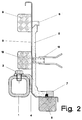
- Fig. 2
- einen Schnitt durch ein Rahmenteil
- Fig. 3
- eine schematische Darstellung für eine mögliche Stellung des Rahmens beim Spritzen
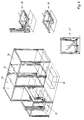
- Fig. 4
- eine schematische Darstellung verschiedener Stationen bei der Herstellung der Schalungsteile
- Fig. 1
- the auxiliary device in a perspective view
- Fig. 2
- a section through a frame part
- Fig. 3
- a schematic representation of a possible position of the frame when spraying
- Fig. 4
- a schematic representation of various stations in the manufacture of the formwork parts
Die Spritzpistole befindet sich im Innern des Rahmen und wird per Hand oder von einem Roboter bedient. Um die Fertigungsformen in die richtige Stellung zur Spritzpistole zu bringen, kann der Rahmen auf einem Handlungsgerät montiert sein, das den Rahmen in Richtung beider Kantenrichtungen verschiebbar, ihn um zwei Kippachsen parallel zu den Kanten verkippbar und ihn um die Hochachse verdrehbar macht. Dies ist in Fig. 3 angedeutet, wo mit 14 der Rahmen 1 samt Fertigungsformen 3 auf einem Drehtisch 14 in zwei zueinander gekippten Stellungen gezeigt ist. Ein die Spritzpistole bedienender Roboter ist mit 15 und die Zentraldüse der Spritzpistole mit 16 bezeichnet.
In Fig. 1 erkennt man an den beiden Eckpunkten der Winkelteile 5 je ein Teil 11, durch das das Winkelteil eine Fase erhält. In die Schalungsteile 5 (Winkelteile) können Aufhängeteile, Schraubhülsen oder auch ein oder mehrere Schweißgründe eingebracht werden, die in günstiger Weise ebenfalls durch Magnete fixiert werden. In Fig. 2 ist eine Schraubhülse 12 mit Magnet 13 gezeigt.The spray gun is located inside the frame and is operated by hand or by a robot. In order to bring the production molds into the correct position relative to the spray gun, the frame can be mounted on a handling device which can be moved in the direction of both edge directions, tilted by two tilting axes parallel to the edges and rotated around the vertical axis. This is indicated in FIG. 3, where the
In Fig. 1 can be seen at the two corner points of the
Bis jetzt wurde beschrieben, wie die gesamte Schalung 3, 6, 7, 8 für die Schalungsteile 5 auf dem Rahmen untergebracht wird. Dies kann in einer speziellen Schalungsstation 20 vor sich gehen, wie dies Fig. 4 zeigt. Von dort gelangt der Rahmen 1 entweder in die Spritz- und Verdichtungsstation 21 oder zwischenzeitlich auch in eine Lagerstation, bestehend aus einem Transportaufzug 22 und Magazinen 23 und 24. Eines dieser Magazine kann auch zur Trocknung (Warmluft) der Schalungsteile dienen. Wie schon erwähnt, enthält die Spritzstation 21 einen Handlungsmechanismus, der bei 25 herausgezeichnet ist, der ein Heben, Drehen, Verschieben und Klippen zuläßt. Bei 26 und 27 sind die Funktion teilweise getrennt gezeichnet.So far it has been described how the
Nach dem Spritzen und Verdichten in Station 21 wird der Rahmen 1 mit den zwei gespritzten Schalungsteilen 5 zum Trocknen und Lagern in die Lagerstation gebracht. Die Lagerstation ist vorzugsweise als intelligentes Lager ausgebildet, das ein automatisches Abrufen der jeweils benötigten speziellen Schalungsteile erlaubt. Dann gelangt der Rahmen mit seinen Teilen wieder zur Schalungsstation 20, wo auch die Entschalung stattfindet. Hier kann das entschalte Schalungsteil von einem Kran übernommen und direkt zu der Stelle 7 im gleichen Werk befördert werden, wo auch das Betonfertigteil gefertigt wird. Das Transportmittel zwischen den Stationen kann z.B. eine Förderkette sein. In dem obigen Beispiel wurden Winkelteile hergestellt. Dies ist keine Notwendigkeit. Es ist z.B. auch möglich, abgerundete Teile zu fertigen oder z.B. auch einfach langgestreckte Teile.After spraying and compacting in
Claims (11)
Applications Claiming Priority (2)
| Application Number | Priority Date | Filing Date | Title |
|---|---|---|---|
| DE4422442 | 1994-06-29 | ||
| DE4422442A DE4422442A1 (en) | 1994-06-29 | 1994-06-29 | Auxiliary device for the production of formwork parts |
Publications (1)
| Publication Number | Publication Date |
|---|---|
| EP0689913A1 true EP0689913A1 (en) | 1996-01-03 |
Family
ID=6521603
Family Applications (1)
| Application Number | Title | Priority Date | Filing Date |
|---|---|---|---|
| EP95109704A Withdrawn EP0689913A1 (en) | 1994-06-29 | 1995-06-22 | Auxiliary device for making shuttering parts |
Country Status (2)
| Country | Link |
|---|---|
| EP (1) | EP0689913A1 (en) |
| DE (1) | DE4422442A1 (en) |
Cited By (3)
| Publication number | Priority date | Publication date | Assignee | Title |
|---|---|---|---|---|
| DE10114398A1 (en) * | 2001-03-23 | 2002-09-26 | Kobra Formen Gmbh | Form frame for a form |
| AU763613B2 (en) * | 1998-09-23 | 2003-07-31 | George Anthony Contoleon | Formwork attachment to frames for concrete walls |
| CN103950094A (en) * | 2014-05-19 | 2014-07-30 | 叶萌 | Concrete building block general multi-cavity combined mould |
Families Citing this family (1)
| Publication number | Priority date | Publication date | Assignee | Title |
|---|---|---|---|---|
| CN112936527A (en) * | 2021-02-20 | 2021-06-11 | 湖北宝业建筑工业化有限公司 | Superimposed shear wall module assembling system and module assembling method |
Citations (8)
| Publication number | Priority date | Publication date | Assignee | Title |
|---|---|---|---|---|
| DE1270466B (en) * | 1962-10-15 | 1968-06-12 | Coignet Construct Edmond | Mold for the production of building bodies from concrete or similar hardening materials |
| EP0006080A1 (en) * | 1978-05-30 | 1979-12-12 | A-Betong AB | A method of manufacturing a laminate |
| GB2028906A (en) * | 1978-08-16 | 1980-03-12 | Ankarswedshus Ab | Foundation Beam and Mould for Casting Same |
| US4404158A (en) * | 1978-03-08 | 1983-09-13 | Olympian Stone Company | Method of making a building panel |
| EP0340185A2 (en) * | 1988-04-28 | 1989-11-02 | Betemi Oy | Production method for a concrete pillar or beam |
| FR2645565A1 (en) * | 1989-04-11 | 1990-10-12 | Public Essais Etudes Lab | Prefabricated facework elements, mould and template for their production |
| US5096648A (en) * | 1988-08-03 | 1992-03-17 | Johnson Brothers Precision Precast Products, Inc. | Method of manufacturing precast concrete articles |
| DE4221679A1 (en) * | 1992-07-02 | 1994-01-13 | Roeder & Spengler Stanz | Prodn. of products containing plastic materials with binder - using appts. which sprays release agent on mould tool, dipping into powdered material, spraying on binder, applying top mould tool and pressing |
-
1994
- 1994-06-29 DE DE4422442A patent/DE4422442A1/en not_active Withdrawn
-
1995
- 1995-06-22 EP EP95109704A patent/EP0689913A1/en not_active Withdrawn
Patent Citations (9)
| Publication number | Priority date | Publication date | Assignee | Title |
|---|---|---|---|---|
| DE1270466B (en) * | 1962-10-15 | 1968-06-12 | Coignet Construct Edmond | Mold for the production of building bodies from concrete or similar hardening materials |
| US4404158A (en) * | 1978-03-08 | 1983-09-13 | Olympian Stone Company | Method of making a building panel |
| US4404158B1 (en) * | 1978-03-08 | 1986-07-22 | ||
| EP0006080A1 (en) * | 1978-05-30 | 1979-12-12 | A-Betong AB | A method of manufacturing a laminate |
| GB2028906A (en) * | 1978-08-16 | 1980-03-12 | Ankarswedshus Ab | Foundation Beam and Mould for Casting Same |
| EP0340185A2 (en) * | 1988-04-28 | 1989-11-02 | Betemi Oy | Production method for a concrete pillar or beam |
| US5096648A (en) * | 1988-08-03 | 1992-03-17 | Johnson Brothers Precision Precast Products, Inc. | Method of manufacturing precast concrete articles |
| FR2645565A1 (en) * | 1989-04-11 | 1990-10-12 | Public Essais Etudes Lab | Prefabricated facework elements, mould and template for their production |
| DE4221679A1 (en) * | 1992-07-02 | 1994-01-13 | Roeder & Spengler Stanz | Prodn. of products containing plastic materials with binder - using appts. which sprays release agent on mould tool, dipping into powdered material, spraying on binder, applying top mould tool and pressing |
Cited By (4)
| Publication number | Priority date | Publication date | Assignee | Title |
|---|---|---|---|---|
| AU763613B2 (en) * | 1998-09-23 | 2003-07-31 | George Anthony Contoleon | Formwork attachment to frames for concrete walls |
| DE10114398A1 (en) * | 2001-03-23 | 2002-09-26 | Kobra Formen Gmbh | Form frame for a form |
| CN103950094A (en) * | 2014-05-19 | 2014-07-30 | 叶萌 | Concrete building block general multi-cavity combined mould |
| CN103950094B (en) * | 2014-05-19 | 2016-04-06 | 叶萌 | The general multi-cavity assembling die of a kind of concrete segment |
Also Published As
| Publication number | Publication date |
|---|---|
| DE4422442A1 (en) | 1996-01-11 |
Similar Documents
| Publication | Publication Date | Title |
|---|---|---|
| EP0674069A1 (en) | Arrangement and method for realising building constructions using masonry blocks and/or shutterings | |
| DE3615460C1 (en) | Device for the production of reinforcements of reinforced concrete slabs for prefabricated ceilings | |
| EP2361739A1 (en) | Assembly for producing finished concrete components | |
| EP1092524A1 (en) | Handling system for a plastic injection moulding machine | |
| DE102006051045A1 (en) | Device for manufacturing elements from hardenable casting mass, preferably at building site places, has transportable container that is designed inside for regulation and withdrawal of movable equipment relevant for manufacturing of element | |
| DE2818515C2 (en) | Form for the production of concrete blocks | |
| EP0689913A1 (en) | Auxiliary device for making shuttering parts | |
| DE2257768A1 (en) | PLANT FOR PRODUCING PRE-FABRICATED CONCRETE PARTS | |
| CH676943A5 (en) | ||
| AT253200B (en) | Method and device for producing masonry from building blocks | |
| EP0415435B1 (en) | Apparatus for making simulated stone concrete blocks | |
| DE2032793C3 (en) | System and method for shuttering, demoulding, cleaning and emptying of mold trolleys | |
| DE19756148C2 (en) | Method and device for producing stone moldings for adapters | |
| EP0536600B1 (en) | Device for producing reinforcements | |
| DE2145746A1 (en) | METHOD AND DEVICE FOR MANUFACTURING A CONCRETE FORMING BLOCK | |
| DE3516477C2 (en) | ||
| AT389842B (en) | SHUTTERING DEVICE FOR PRODUCING FINISHED GARAGES | |
| DE3714580C1 (en) | Device for producing recesses, oblique cuts, severing cuts or the like in the case of precast concrete floor slabs or the like | |
| DE3248333A1 (en) | Machine for manufacturing moulded bodies made of concrete | |
| DE4133589A1 (en) | Steel reinforcement mfr. for concrete slabs - involves industrial robots to place reinforcement elements in position | |
| DE4028884A1 (en) | Frame to facilitate building of vertical wall - has platform which can beraised or lowered to support building material | |
| DE2516401B2 (en) | System for the construction and dismantling of mixed-bed heaps | |
| DE3344034A1 (en) | Installation for assembly-line production of precast concrete parts, in particular of large panels | |
| DE3742417A1 (en) | Process and apparatus for producing from concrete a slightly conical container which is open at the top | |
| DE2902287C2 (en) | Heat treatment furnace for hardening concrete masses poured into molds and plant for the production of precast concrete parts |
Legal Events
| Date | Code | Title | Description |
|---|---|---|---|
| PUAI | Public reference made under article 153(3) epc to a published international application that has entered the european phase |
Free format text: ORIGINAL CODE: 0009012 |
|
| AK | Designated contracting states |
Kind code of ref document: A1 Designated state(s): AT BE CH DE ES FR LI NL SE |
|
| RBV | Designated contracting states (corrected) |
Designated state(s): AT BE CH DE ES FR LI NL SE |
|
| STAA | Information on the status of an ep patent application or granted ep patent |
Free format text: STATUS: THE APPLICATION IS DEEMED TO BE WITHDRAWN |
|
| 18D | Application deemed to be withdrawn |
Effective date: 19960704 |