EP0688909A1 - Electrically controlled water tap - Google Patents
Electrically controlled water tap Download PDFInfo
- Publication number
- EP0688909A1 EP0688909A1 EP95108152A EP95108152A EP0688909A1 EP 0688909 A1 EP0688909 A1 EP 0688909A1 EP 95108152 A EP95108152 A EP 95108152A EP 95108152 A EP95108152 A EP 95108152A EP 0688909 A1 EP0688909 A1 EP 0688909A1
- Authority
- EP
- European Patent Office
- Prior art keywords
- water
- valve
- support body
- component
- fitting according
- Prior art date
- Legal status (The legal status is an assumption and is not a legal conclusion. Google has not performed a legal analysis and makes no representation as to the accuracy of the status listed.)
- Granted
Links
Images


Classifications
-
- E—FIXED CONSTRUCTIONS
- E03—WATER SUPPLY; SEWERAGE
- E03C—DOMESTIC PLUMBING INSTALLATIONS FOR FRESH WATER OR WASTE WATER; SINKS
- E03C1/00—Domestic plumbing installations for fresh water or waste water; Sinks
- E03C1/02—Plumbing installations for fresh water
- E03C1/05—Arrangements of devices on wash-basins, baths, sinks, or the like for remote control of taps
- E03C1/055—Electrical control devices, e.g. with push buttons, control panels or the like
- E03C1/057—Electrical control devices, e.g. with push buttons, control panels or the like touchless, i.e. using sensors
Definitions
- the invention relates to a water fitting, in particular a non-contact controlled water fitting, with a or the like on a washstand, a building wall.
- fixable water inlet and water outlet fittings having body, in which at least one electrically operated valve, an electrical control and a battery provided as an electrical energy source is arranged.
- Such water fittings are known, the controller and the battery being installed in the fitting body.
- the battery can be replaced via an opening that can be closed with a lid, while the control is arranged stationary in the valve body.
- the invention has for its object to improve the arrangement of the controller and the battery in the valve body, so that both the battery and the controller is easily accessible and replaceable at all times.
- control with the battery is provided in a slide-in component which can be inserted into a receiving space of the fitting body and can be fixed in the plug-in position, the control arranged in the slide-in component being connected to at least one electrically operated valve via a connecting cable.
- the electrical or electronic control system with the battery as a unit can be easily installed and removed, thus making it easy to replace the battery and / or the control system.
- the fitting body can be manufactured separately with at least one electrical valve or solenoid valve and can be completed at a later time by plugging the connecting cable and inserting the insert component with the control for the water fitting.
- a presence detector can also be expediently arranged in the plug-in component in addition to the electronic control and the battery.
- the fitting body can advantageously be provided with an approximately cylindrical support body in which a receiving space is formed with a radial insertion opening, the support body or the like on one end face with a tensioning device on a washstand. can be fastened and has at least one supply line for water, while an electric valve or solenoid valve is provided on the opposite side.
- a sleeve-shaped outer body with a radially protruding outlet part can be plugged onto the support body, which in the plug-in position together with the insertion component from one of the rear radially screw is in the inserted position.
- a mixing valve can be arranged in the fitting body, with which tempered mixed water can be produced from supplied cold and hot water. The mixing valve can be expediently adjusted with a lever that is inserted radially into the valve body.
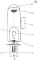
- the water fitting shown in FIGS. 1 and 2 consists of a fitting body 1, a slide-in component 2, an electromagnetically operated valve 3 and a mixing valve 4.
- the valve body 1 is formed from an approximately cylindrical support body 11 and a sleeve-shaped outer body 12.
- the support body 11 carries on one end face a tensioning device 1121, with which the support body 11 a washstand or the like is firmly clamped.
- the two supply lines for cold and hot water are led into the support body 11 on this end face.
- a receiving space 111 is formed radially in the support body 11.
- the two feed lines 113 are guided through the receiving space 111 and soldered in a water duct for the mixing valve 4 above the receiving space 111.
- the mixing valve 4 is designed as a rotary slide valve, which can be set with a lever 41 which is guided radially into the supporting body 11.
- the rotary lobe has two opposing throttle slots in the area of the two feed channels for cold and hot water, the throttle slots being arranged in such a way that the throttle slot for e.g. cold water is reduced when the throttle slot is turned, while the other throttle slot for the hot water is simultaneously reduced by the same Amount is increased so that the total flow rate remains the same, but the mixing ratio or the temperature of the mixed water generated is changed accordingly.
- the mixed water generated in the mixing valve 4 is fed to the solenoid valve 3 and discharged from here via a radial outlet opening 31.
- the outer body 12 can be plugged onto the upright support body 11 after the fixed mounting on the washstand etc., two axially offset sealing rings 114 being provided on the lateral surface of the support body 11 in the region of the electromagnetically operated valve 3, one with the outlet opening 31 in Restrict the connected radial outlet 115 for mixed water.
- the outlet 115 is connected to an outlet part 121 and a water outlet mouthpiece 1212 via an opening 1211.
- the insert component 2 can be inserted radially into the receiving space 111.
- An electronic control 21 is arranged in the plug-in component 2 and can be connected to the electromagnetically operated valve 3 via a connecting cable 211 and a plug connection 2111.
- a presence detector 26 is provided, which has a transmission diode 261 and a reception diode 262 behind a window 23.
- the electronic control 21 with the presence detector 26 are supplied with electrical energy from a battery 22.
- the battery 22 is arranged in a battery receiving space 220, which can be closed with a cover 24 by means of a screw 240. In the inserted state, the battery 22 bears with its poles against correspondingly resilient contacts 221 of the control 21.
- the immersion depth of the insert component 2 in the receiving space 111 is determined by a protrusion 25 on the insert component 2, which comes into contact with the support body 11 in the inserted position.
- a radially screw-in screw 13 is also provided for fixing in the plug-in position.
- the insert component 2 carries in the front area on the outer circumference a seal 20 which bears against the support body 2 in the plug-in position and protects the control against splash water.
- the water fitting that can be installed as a normal single-hole water mixer is largely protected against willful destruction by the screw 13, which is only accessible from the rear.
- the maintenance personnel can replace a battery or the entire control system in a relatively simple manner without great expenditure of time by simply unscrewing the screw 13 and pulling out the plug-in component 2.
- the used battery 22 can be opened by opening the cover 24 removed and replaced with a new one.
- the insertion component 2 can be pushed back into the receiving space 111 and secured with the screw 13, so that the water fitting is ready for operation again.
- the electronic control 21 or the presence detector 26 is defective, the entire plug-in component 2 can be easily replaced. Only a plug connection 2111 has to be actuated here.
- valve 3 Even if the electromagnetically operated valve 3 is defective, it is relatively easily accessible, since the valve 3 is arranged on the end face of the support body 11 opposite the tensioning device 1121. After unscrewing the screw 13 and pulling out the insertion component 2, the outer body 12 can simply be pulled off the support body 11. Thereafter, the valve 3 is freely accessible, which is arranged with its electromagnetic region 32 in a chamber 122 of the outer body 12 not acted upon by water. The screw 13 arranged on the rear of the fitting body 1 thus secures both the insertion component 2 and the outer body 12 on the support body 11 in the plug-in position.
Landscapes
- Health & Medical Sciences (AREA)
- Life Sciences & Earth Sciences (AREA)
- Engineering & Computer Science (AREA)
- Hydrology & Water Resources (AREA)
- Public Health (AREA)
- Water Supply & Treatment (AREA)
- Domestic Plumbing Installations (AREA)
- Treatment Of Water By Ion Exchange (AREA)
- Coupling Device And Connection With Printed Circuit (AREA)
- Circuit Arrangement For Electric Light Sources In General (AREA)
Abstract
Description
Die Erfindung betrifft eine Wasserarmatur, insbesondere berührungslos gesteuerte Wasserarmatur, mit einem an einem Waschtisch, einer Gebäudewand o.dgl. befestigbaren Wassereinlaß- und Wasserauslaßöffnungen aufweisenden Armaturenkörper, in dem wenigstens ein elektrisch betriebenes Ventil, eine elektrische Steuerung und eine als elektrische Energiequelle vorgesehene Batterie angeordnet ist.
Derartige Wasserarmaturen sind bekannt, wobei die Steuerung und die Batterie im Armaturenkörper installiert sind. Die Batterie ist über eine mit einem Deckel verschließbare Öffnung austauschbar, während die Steuerung stationär im Armaturenkörper angeordnet ist.The invention relates to a water fitting, in particular a non-contact controlled water fitting, with a or the like on a washstand, a building wall. fixable water inlet and water outlet fittings having body, in which at least one electrically operated valve, an electrical control and a battery provided as an electrical energy source is arranged.
Such water fittings are known, the controller and the battery being installed in the fitting body. The battery can be replaced via an opening that can be closed with a lid, while the control is arranged stationary in the valve body.
Der Erfindung liegt die Aufgabe zugrunde, die Anordnung der Steuerung und der Batterie in dem Armaturenkörper zu verbessern, so daß sowohl die Batterie als auch die Steuerung jederzeit leicht zugänglich und austauschbar ist.The invention has for its object to improve the arrangement of the controller and the battery in the valve body, so that both the battery and the controller is easily accessible and replaceable at all times.
Diese Aufgabe wird erfindungsgemäß dadurch gelöst, daß die Steuerung mit der Batterie in einem Einschubbauteil vorgesehen ist, welches in einen Aufnahmeraum des Armaturenkörpers einschiebbar und in der Stecklage fixierbar ist, wobei die im Einschubbauteil angeordnete Steuerung über ein Verbindungskabel mit wenigstens einem elektrisch betriebenen Ventil verbunden ist.
Weitere Ausgestaltungen der Erfindung sind in den Ansprüchen 2 bis 9 angegeben.This object is achieved in that the control with the battery is provided in a slide-in component which can be inserted into a receiving space of the fitting body and can be fixed in the plug-in position, the control arranged in the slide-in component being connected to at least one electrically operated valve via a connecting cable.
Further refinements of the invention are specified in
Die mit der Erfindung erzielbaren Vorteile bestehen insbesondere darin, daß die elektrische bzw. elektronische Steuerung mit der Batterie als Einheit leicht ein- und ausbaubar ist und somit ein einfaches Auswechseln der Batterie und/oder der Steuerung ermöglicht ist. Insbesondere kann der Armaturenkörper mit wenigstens einem elektrischen Ventil bzw. Magnetventil separat hergestellt werden und zu einem späteren Zeitpunkt durch Zusammenstecken des Verbindungskabels und Einsetzen des Einschubbauteils mit der Steuerung zur Wasserarmatur komplettiert werden.
In weiterer Ausgestaltung kann zweckmäßig im Einschubbauteil neben der elektronischen Steuerung und der Batterie auch ein Anwesenheitsdetektor angeordnet werden.
Vorteilhaft kann der Armaturenkörper bei der erfindungsgemäßen Ausbildung mit einem etwa zylindrischen Tragkörper, in dem ein Aufnahmeraum mit einer radialen Einschuböffnung ausgebildet ist, versehen werden, wobei der Tragkörper an der einen Stirnseite mit einer Spannvorrichtung an einem Waschtisch o.dgl. befestigbar ist und wenigstens eine Zuführleitung für Wasser aufweist, während auf der gegenüberliegenden Seite ein elektrisches Ventil bzw. Magnetventil vorgesehen ist. Auf den Tragkörper kann ein hülsenförmiger Außenkörper mit einem radial vorstehenden Auslaufteil aufgesteckt werden, der in der Stecklage zusammen mit dem Einschubbauteil von einer von der Rückseite radial eindrehbaren Schraube in der Stecklage ist.
Außerdem kann in dem Armaturenkörper ein Mischventil angeordnet sein, mit dem temperiertes Mischwasser aus zugeführtem Kalt- und Warmwasser erzeugbar ist. Das Mischventil kann hierbei zweckmäßig mit einem radial in den Armaturenkörper hineingeführten Hebel eingestellt werden.The advantages that can be achieved with the invention are, in particular, that the electrical or electronic control system with the battery as a unit can be easily installed and removed, thus making it easy to replace the battery and / or the control system. In particular, the fitting body can be manufactured separately with at least one electrical valve or solenoid valve and can be completed at a later time by plugging the connecting cable and inserting the insert component with the control for the water fitting.
In a further embodiment, a presence detector can also be expediently arranged in the plug-in component in addition to the electronic control and the battery.
In the embodiment according to the invention, the fitting body can advantageously be provided with an approximately cylindrical support body in which a receiving space is formed with a radial insertion opening, the support body or the like on one end face with a tensioning device on a washstand. can be fastened and has at least one supply line for water, while an electric valve or solenoid valve is provided on the opposite side. A sleeve-shaped outer body with a radially protruding outlet part can be plugged onto the support body, which in the plug-in position together with the insertion component from one of the rear radially screw is in the inserted position.
In addition, a mixing valve can be arranged in the fitting body, with which tempered mixed water can be produced from supplied cold and hot water. The mixing valve can be expediently adjusted with a lever that is inserted radially into the valve body.
Ein Ausführungsbeispiel der Erfindung ist in der Zeichnung dargestellt und wird im folgenden näher beschrieben. Es zeigt
Figur 1- eine Wasserarmatur mit elektrischer Steuerung im Seitenschnitt;
Figur 2- die in
Figur 1 gezeigte Wasserarmatur in Vorderansicht; Figur 3- ein in
Figur 1 gezeigtes Einschubbauteil in vergrößerter Darstellung im Längsschnitt ohne eingesetzte Batterie; Figur 4- das in
Figur 3 gezeigte Einschubbauteil in der Schnittebene IV.
- Figure 1
- a water tap with electrical control in side section;
- Figure 2
- the water fitting shown in Figure 1 in front view;
- Figure 3
- a slide-in component shown in Figure 1 in an enlarged view in longitudinal section without a battery;
- Figure 4
- the slide-in component shown in Figure 3 in the section plane IV.
Die in Figur 1 und 2 gezeigte Wasserarmatur besteht aus einem Armaturenkörper 1, einem Einschubbauteil 2, einem elektromagnetisch betriebenen Ventil 3 und einem Mischventil 4.
Der Armaturenkörper 1 ist aus einem etwa zylindrischen Tragkörper 11 und einem hülsenförmigen Außenkörper 12 gebildet.
Der Tragkörper 11 trägt an der einen Stirnseite eine Spannvorrichtung 1121, mit der der Tragkörper 11 auf einem Waschtisch o.dgl. fest verspannbar ist. Außerdem sind an dieser Stirnseite die beiden Zuführleitungen für Kalt- und Warmwasser in den Tragkörper 11 hineingeführt. Von der Mantelfläche ausgesehen, ist radial in dem Tragkörper 11 ein Aufnahmeraum 111 ausgebildet. Durch den Aufnahmeraum 111 hindurch sind die beiden Zuführleitungen 113 geführt und oberhalb des Aufnahmeraums 111 in einer Wasserführung für das Mischventil 4 eingelötet. Das Mischventil 4 ist als Drehkolbenschieber ausgebildet, welcher mit einem radial in den Tragkörper 11 hineingeführten Hebel 41 gestellt werden kann. Der Drehkolben hat hierbei zwei gegenläufige Drosselschlitze im Bereich der beiden hintereinander liegenden Zuführungskanäle für Kalt- und Warmwasser, wobei die Drosselschlitze so angeordnet sind, daß bei einer Drehbewegung der Drosselschlitz für z.B. Kaltwasser verringert wird, während der andere Drosselschlitz für das Warmwasser gleichzeitig um den gleichen Betrag vergrößert wird, so daß die Gesamtdurchflußmenge gleich bleibt, aber das Mischungsverhältnis bzw. die Temperatur des erzeugten Mischwassers entsprechend geändert wird. Das in dem Mischventil 4 erzeugte Mischwasser wird dem Magnetventil 3 zugeführt und von hier über eine radiale Auslaßöffnung 31 abgegeben.The water fitting shown in FIGS. 1 and 2 consists of a
The
The
Auf dem aufrechtstehenden Tragkörper 11 kann nach der Festmontage auf dem Waschtisch etc. der Außenkörper 12 aufgesteckt werden, wobei an der Mantelfläche des Tragkörpers 11 im Bereich des elektromagnetisch betriebenen Ventils 3 zwei axial zueinander versetzte Dichtringe 114 vorgesehen sind, die einen mit der Auslaßöffnung 31 in Verbindung stehenden radialen Auslaß 115 für Mischwasser eingrenzen. Über einen Durchbruch 1211 ist der Auslaß 115 mit einem Auslaßteil 121 und einem Wasseraustrittsmundstück 1212 verbunden.The
Das Einschubbauteil 2 kann radial in den Aufnahmeraum 111 eingeschoben werden. In dem Einschubbauteil 2 ist eine elektronische Steuerung 21 angeordnet, die über ein Verbindungskabel 211 und eine Steckverbindung 2111 mit dem elektromagnetisch betriebenen Ventil 3 verbunden werden kann. Außerdem ist ein Anwesenheitsdetektor 26 vorgesehen, der hinter einem Fenster 23 eine Sendediode 261 und eine Empfangsdiode 262 aufweist. Die elektronische Steuerung 21 mit dem Anwesenheitsdetektor 26 werden mit elektrischer Energie von einer Batterie 22 versorgt. Die Batterie 22 ist in einem Batterieaufnahmeraum 220 angeordnet, welcher mit einem Deckel 24 mit Hilfe einer Schraube 240 verschließbar ist. Die Batterie 22 liegt im eingesetzten Zustand mit ihren Polen an entsprechend federnd ausgebildeten Kontakten 221 der Steuerung 21 an. Die Eintauchtiefe des Einschubbauteils 2 in den Aufnahmeraum 111 wird durch einen Vorsprung 25 am Einschubbauteil 2 bestimmt, der in der Einstecklage an dem Tragkörper 11 zur Anlage gelangt. Zur Fixierung in der Stecklage ist außerdem eine radial eindrehbare Schraube 13 vorgesehen. Schließlich trägt das Einschubbauteil 2 im vorderen Bereich am Außenumfang eine Dichtung 20, die in der Stecklage am Tragkörper 2 anliegt und die Steuerung gegenüber Spritzwasser schützt.The
Die als normale Einlochwassermischbatterie installierbare Wasserarmatur ist durch die nur von der Rückseite her zugänglichen Schraube 13 gegen mutwillige Zerstörung weitgehend geschützt. Das Auswechseln einer Batterie oder aber der gesamten Steuerung kann vom Wartungspersonal relativ einfach ohne großen Zeitaufwand durch einfaches Herausdrehen der Schraube 13 und dem Herausziehen des Einschubbauteils 2 erfolgen. Hiernach kann durch Öffnen des Deckels 24 die verbrauchte Batterie 22 herausgenommen und durch eine neue ersetzt werden. Nach dem erneuten Verschluß des Deckels 24 kann das Einschubbauteil 2 wieder in den Aufnahmeraum 111 eingeschoben und mit der Schraube 13 gesichert werden, so daß die Wasserarmatur wieder betriebsbereit ist. Für den Fall, daß die elektronische Steuerung 21 oder der Anwesenheitsdetektor 26 defekt ist, kann das gesamte Einschubbauteil 2 einfach ausgewechselt werden. Hierbei ist lediglich eine Steckverbindung 2111 zu betätigen.
Auch bei einem Defekt des elektromagnetisch betriebenen Ventils 3 ist dieses relativ leicht zugängig, da das Ventil 3 an der der Spannvorrichtung 1121 gegenüberliegenden Stirnseite des Tragkörpers 11 angeordnet ist. Nach dem Herausdrehen der Schraube 13 und dem Herausziehen des Einschubbauteils 2 kann der Außenkörper 12 einfach von dem Tragkörper 11 abgezogen werden. Hiernach ist das Ventil 3 frei zugängig, welches mit seinem elektromagnetischen Bereich 32 in einer nicht vom Wasser beaufschlagten Kammer 122 des Außenkörpers 12 angeordnet ist. Die an der Rückseite des Armaturenkörpers 1 angeordnete Schraube 13 sichert somit sowohl das Einschubbauteil 2 als auch den Außenkörper 12 am Tragkörper 11 in der Stecklage.The water fitting that can be installed as a normal single-hole water mixer is largely protected against willful destruction by the
Even if the electromagnetically operated
Claims (9)
Applications Claiming Priority (2)
| Application Number | Priority Date | Filing Date | Title |
|---|---|---|---|
| DE4420330A DE4420330A1 (en) | 1994-06-10 | 1994-06-10 | Water tap with electrical control |
| DE4420330 | 1994-06-10 |
Publications (2)
| Publication Number | Publication Date |
|---|---|
| EP0688909A1 true EP0688909A1 (en) | 1995-12-27 |
| EP0688909B1 EP0688909B1 (en) | 1999-03-10 |
Family
ID=6520289
Family Applications (1)
| Application Number | Title | Priority Date | Filing Date |
|---|---|---|---|
| EP95108152A Expired - Lifetime EP0688909B1 (en) | 1994-06-10 | 1995-05-29 | Electrically controlled water tap |
Country Status (7)
| Country | Link |
|---|---|
| US (1) | US5586746A (en) |
| EP (1) | EP0688909B1 (en) |
| JP (1) | JPH0841938A (en) |
| AT (1) | ATE177493T1 (en) |
| DE (2) | DE4420330A1 (en) |
| DK (1) | DK0688909T3 (en) |
| ES (2) | ES2131727T3 (en) |
Cited By (2)
| Publication number | Priority date | Publication date | Assignee | Title |
|---|---|---|---|---|
| WO2002016704A1 (en) | 2000-08-23 | 2002-02-28 | Geberit Technik Ag | Water fitting |
| EP2169123A1 (en) | 2008-09-24 | 2010-03-31 | Geberit International AG | Contact-less controlled water fitting |
Families Citing this family (54)
| Publication number | Priority date | Publication date | Assignee | Title |
|---|---|---|---|---|
| USRE37888E1 (en) * | 1996-03-06 | 2002-10-22 | Eugen Cretu-Petra | Water faucet with touchless controls |
| US5868311A (en) * | 1997-09-03 | 1999-02-09 | Cretu-Petra; Eugen | Water faucet with touchless controls |
| DE19710782C2 (en) * | 1997-03-17 | 2002-08-01 | Ideal Standard | plumbing fixture |
| EP1018062A4 (en) * | 1997-09-18 | 2001-05-16 | Alexander Mayer | Improvements in automated fluid flow systems |
| DE19754232B4 (en) | 1997-12-06 | 2007-04-19 | Grohe Ag | Water fitting with electrical control |
| DE29800536U1 (en) * | 1998-01-16 | 1998-03-05 | Mueller A & K Gmbh Co Kg | Solenoid valve, especially for sanitary fittings |
| US5988588A (en) * | 1998-03-16 | 1999-11-23 | Asloan Valve Company | Control module for battery-operated faucet |
| US6082407A (en) * | 1999-03-03 | 2000-07-04 | Speakman Company | Automatic faucet assembly with mating housing and high endurance finish |
| USD431285S (en) * | 1999-09-09 | 2000-09-26 | Speakman Company | Automatic faucet with mated housing |
| US6219857B1 (en) * | 1999-12-16 | 2001-04-24 | Hydrotek Corporation | Sensor device for use with a flush valve |
| DE10148675C1 (en) * | 2001-10-02 | 2003-12-04 | Mepa Pauli Und Menden Gmbh Wie | Electronically-controlled water tap with proximity detector forming part of function block sealed in tap body via O-ring for preventing contact with water |
| US7921480B2 (en) | 2001-11-20 | 2011-04-12 | Parsons Natan E | Passive sensors and control algorithms for faucets and bathroom flushers |
| AU2002351230A1 (en) * | 2001-12-04 | 2003-06-17 | Arichell Technologies, Inc. | Electronic faucets for long-term operation |
| US6612541B2 (en) * | 2002-01-03 | 2003-09-02 | I-Con Systems, Inc. | Control valve retrofit for pneumatic plumbing fixture |
| US9169626B2 (en) | 2003-02-20 | 2015-10-27 | Fatih Guler | Automatic bathroom flushers |
| HUP0201392A2 (en) * | 2002-04-29 | 2004-03-01 | KEROX-Multipolár II. Ipari és Kereskedelmi Kft. | Mixing faucet with electromagnetic valve |
| US7731154B2 (en) | 2002-12-04 | 2010-06-08 | Parsons Natan E | Passive sensors for automatic faucets and bathroom flushers |
| WO2006058650A1 (en) * | 2004-11-29 | 2006-06-08 | Cornelis Bolderheij Fok | Multi-functional fitting |
| US7625667B2 (en) * | 2005-03-14 | 2009-12-01 | Masco Corporation Of Indiana | Battery box assembly |
| US7650653B2 (en) * | 2005-11-14 | 2010-01-26 | Geberit Technik Ag | Modular electrically-operated faucet |
| MX2008012417A (en) * | 2006-03-30 | 2008-10-07 | Kohler Co | Faucet sensor mounting assembly. |
| CN2886267Y (en) * | 2006-04-20 | 2007-04-04 | 上海澳柯林水暖器材有限公司 | Induction faucet mounting structure |
| US7766043B2 (en) | 2006-05-26 | 2010-08-03 | Masco Corporation Of Indiana | Faucet including a molded waterway assembly |
| US8991425B2 (en) | 2006-05-26 | 2015-03-31 | Delta Faucet Company | Waterway assembly including an overmolded support plate |
| US7743438B2 (en) * | 2006-12-28 | 2010-06-29 | Jan-Sun Chen | Anchor structure for sensors of faucets |
| US7806141B2 (en) | 2007-01-31 | 2010-10-05 | Masco Corporation Of Indiana | Mixing valve including a molded waterway assembly |
| US8296875B2 (en) | 2007-09-20 | 2012-10-30 | Bradley Fixtures Corporation | Lavatory system |
| KR100840867B1 (en) * | 2007-10-12 | 2008-06-23 | 지성만 | Automatic screw tap with built-in eletronic valve and control valve of cold and warm water quantity |
| WO2009126887A1 (en) | 2008-04-10 | 2009-10-15 | Masco Corporation Of Indiana | Molded waterway for a two handle faucet |
| US8695625B2 (en) | 2008-06-25 | 2014-04-15 | Masco Corporation Of Indiana | Centerset faucet with mountable spout |
| MX366199B (en) | 2009-10-07 | 2019-06-25 | Bradley Fixtures Corp | Lavatory system with hand dryer. |
| US8739826B2 (en) | 2011-03-11 | 2014-06-03 | Masco Corporation Of Indiana | Centerset faucet body and method of making same |
| US9695579B2 (en) | 2011-03-15 | 2017-07-04 | Sloan Valve Company | Automatic faucets |
| WO2012125213A1 (en) | 2011-03-15 | 2012-09-20 | Sloan Valve Company | Automatic faucets |
| US9267736B2 (en) | 2011-04-18 | 2016-02-23 | Bradley Fixtures Corporation | Hand dryer with point of ingress dependent air delay and filter sensor |
| US9170148B2 (en) | 2011-04-18 | 2015-10-27 | Bradley Fixtures Corporation | Soap dispenser having fluid level sensor |
| USD677366S1 (en) | 2011-09-26 | 2013-03-05 | Chung-Chia Chen | Touch-free faucet |
| US8931500B2 (en) | 2012-02-17 | 2015-01-13 | Masco Corporation Of Indiana | Two handle centerset faucet |
| EP2823107A4 (en) | 2012-03-07 | 2016-06-15 | Moen Inc | Electronic plumbing fixture fitting |
| ES2682022T3 (en) | 2012-03-21 | 2018-09-18 | Bradley Fixtures Corporation | Pile and hand drying system |
| US10100501B2 (en) | 2012-08-24 | 2018-10-16 | Bradley Fixtures Corporation | Multi-purpose hand washing station |
| ITTO20120828A1 (en) * | 2012-09-24 | 2014-03-25 | Fiore S P A | TAP WITH ELECTRONIC CONTROL AND ADAPTER FOR SOLENOID VALVE. |
| US9603496B1 (en) | 2013-03-15 | 2017-03-28 | David C. Hartman | Toilet seat assembly |
| US9920508B2 (en) * | 2014-06-09 | 2018-03-20 | Chung-Chia Chen | Touch-free faucets and sensors |
| EP3064660A1 (en) * | 2015-03-04 | 2016-09-07 | Franke Water Systems AG | Electronically controlled sanitary device |
| WO2017111734A1 (en) * | 2015-12-26 | 2017-06-29 | Eczacibaşi Yapi Gereçleri̇ Sanayi̇ Ve Ti̇caret Anoni̇m Şi̇rketi̇ | Flushing system with am integrated sensor and ceramic sanitary ware comprising the flushing system |
| US10544571B2 (en) | 2016-03-25 | 2020-01-28 | Spectrum Brands, Inc. | Electronic faucet with spatial orientation control system |
| DE102016108045A1 (en) | 2016-04-29 | 2017-11-02 | A. u. K. Müller GmbH & Co. KG | Armaturauslass and fitting |
| US10041236B2 (en) | 2016-06-08 | 2018-08-07 | Bradley Corporation | Multi-function fixture for a lavatory system |
| US11015329B2 (en) | 2016-06-08 | 2021-05-25 | Bradley Corporation | Lavatory drain system |
| CN106352138B (en) * | 2016-10-11 | 2019-05-14 | 张少亮 | A kind of automatic sensing tap based on gesture control application |
| DE202017103194U1 (en) | 2017-05-26 | 2018-08-28 | Neoperl Gmbh | sanitary valve |
| JP7051534B2 (en) * | 2018-03-29 | 2022-04-11 | 株式会社Lixil | Faucet device |
| ES2766923B2 (en) * | 2018-12-13 | 2021-10-01 | Sedal S L U | CARTRIDGE FOR TAP WITH CABLE ROUTING FOR MANUAL MOBILE OPERATION CONTROL AND TAP WITH ELECTRONIC CONTROL THAT CONTAINS IT |
Citations (6)
| Publication number | Priority date | Publication date | Assignee | Title |
|---|---|---|---|---|
| DE2721154A1 (en) * | 1977-05-11 | 1978-11-16 | Sprenger Albin Kg | Water supply piping for wash basin - has opto-electric proximity switch, light beam sender and receiver, control circuit and valve for automatic filling |
| JPS6479481A (en) * | 1987-09-21 | 1989-03-24 | Toto Ltd | Automatic faucet |
| JPH02140337A (en) * | 1988-08-08 | 1990-05-30 | Mic Kogyo Kk | Automatic water cock |
| EP0391765A1 (en) * | 1989-04-07 | 1990-10-10 | Les Robinets Presto Société Anonyme | Remotely actuated tap |
| EP0409998A1 (en) * | 1989-01-13 | 1991-01-30 | Toto Ltd. | Automatic faucet |
| DE9211577U1 (en) * | 1992-08-28 | 1992-11-12 | Eckerfeld, Erika, 5628 Heiligenhaus, De |
Family Cites Families (5)
| Publication number | Priority date | Publication date | Assignee | Title |
|---|---|---|---|---|
| DE921157C (en) * | 1942-10-31 | 1954-12-09 | Fernseh Gmbh | Method of operating modulation storage tubes |
| US4839039B2 (en) * | 1986-02-28 | 1998-12-29 | Recurrent Solutions Ltd | Automatic flow-control device |
| US5060323A (en) * | 1989-07-12 | 1991-10-29 | Bauer Industries, Inc. | Modular system for automatic operation of a water faucet |
| US5169118A (en) * | 1992-02-11 | 1992-12-08 | Sloan Valve Company | Sensor-operated battery-powered flush valve |
| US5431181A (en) * | 1993-10-01 | 1995-07-11 | Zurn Industries, Inc. | Automatic valve assembly |
-
1994
- 1994-06-10 DE DE4420330A patent/DE4420330A1/en not_active Withdrawn
-
1995
- 1995-05-25 JP JP7126496A patent/JPH0841938A/en active Pending
- 1995-05-29 ES ES95108152T patent/ES2131727T3/en not_active Expired - Lifetime
- 1995-05-29 AT AT95108152T patent/ATE177493T1/en not_active IP Right Cessation
- 1995-05-29 EP EP95108152A patent/EP0688909B1/en not_active Expired - Lifetime
- 1995-05-29 DE DE59505251T patent/DE59505251D1/en not_active Expired - Fee Related
- 1995-05-29 DK DK95108152T patent/DK0688909T3/en active
- 1995-06-08 ES ES09501566U patent/ES1031340Y/en not_active Expired - Lifetime
- 1995-06-08 US US08/488,479 patent/US5586746A/en not_active Expired - Fee Related
Patent Citations (6)
| Publication number | Priority date | Publication date | Assignee | Title |
|---|---|---|---|---|
| DE2721154A1 (en) * | 1977-05-11 | 1978-11-16 | Sprenger Albin Kg | Water supply piping for wash basin - has opto-electric proximity switch, light beam sender and receiver, control circuit and valve for automatic filling |
| JPS6479481A (en) * | 1987-09-21 | 1989-03-24 | Toto Ltd | Automatic faucet |
| JPH02140337A (en) * | 1988-08-08 | 1990-05-30 | Mic Kogyo Kk | Automatic water cock |
| EP0409998A1 (en) * | 1989-01-13 | 1991-01-30 | Toto Ltd. | Automatic faucet |
| EP0391765A1 (en) * | 1989-04-07 | 1990-10-10 | Les Robinets Presto Société Anonyme | Remotely actuated tap |
| DE9211577U1 (en) * | 1992-08-28 | 1992-11-12 | Eckerfeld, Erika, 5628 Heiligenhaus, De |
Non-Patent Citations (2)
| Title |
|---|
| PATENT ABSTRACTS OF JAPAN vol. 013, no. 287 (M - 844) 30 June 1989 (1989-06-30) * |
| PATENT ABSTRACTS OF JAPAN vol. 014, no. 378 (M - 1011) 15 August 1990 (1990-08-15) * |
Cited By (4)
| Publication number | Priority date | Publication date | Assignee | Title |
|---|---|---|---|---|
| WO2002016704A1 (en) | 2000-08-23 | 2002-02-28 | Geberit Technik Ag | Water fitting |
| US6671898B1 (en) * | 2000-08-23 | 2004-01-06 | Geberit Technik Ag | Water fitting |
| EP2169123A1 (en) | 2008-09-24 | 2010-03-31 | Geberit International AG | Contact-less controlled water fitting |
| US8448271B2 (en) | 2008-09-24 | 2013-05-28 | Geberit International Ag | Faucet controlled in a contactless manner |
Also Published As
| Publication number | Publication date |
|---|---|
| US5586746A (en) | 1996-12-24 |
| ES2131727T3 (en) | 1999-08-01 |
| ATE177493T1 (en) | 1999-03-15 |
| DE4420330A1 (en) | 1995-12-14 |
| DE59505251D1 (en) | 1999-04-15 |
| ES1031340U (en) | 1995-12-16 |
| ES1031340Y (en) | 1996-05-16 |
| DK0688909T3 (en) | 1999-09-27 |
| JPH0841938A (en) | 1996-02-13 |
| EP0688909B1 (en) | 1999-03-10 |
Similar Documents
| Publication | Publication Date | Title |
|---|---|---|
| EP0688909B1 (en) | Electrically controlled water tap | |
| DE3718039C2 (en) | Electronically temperature-controlled mixer tap | |
| DE4420332A1 (en) | Water tap | |
| DE10148675C1 (en) | Electronically-controlled water tap with proximity detector forming part of function block sealed in tap body via O-ring for preventing contact with water | |
| EP3004473A2 (en) | Control cartridge for sanitary fittings | |
| WO1998041787A1 (en) | Electrically operated fitting | |
| EP1595318A1 (en) | Wire feedthrough | |
| EP1978165A2 (en) | Mounting device for a water fitting | |
| DE19856157B4 (en) | Connection block for sanitary fittings | |
| DE3022706C2 (en) | Single-hole mixer tap | |
| EP2468964B1 (en) | Modular flush-mounted system with a central flush-mounted mixed module | |
| EP3173538A1 (en) | Connection device | |
| EP0790448B1 (en) | Sanitary fitting | |
| DE3116502A1 (en) | Set of structural elements for converting two-handle flush-mounted fittings | |
| WO2020200633A1 (en) | Sanitary fitting comprising a plug unit | |
| DE10125981C5 (en) | Sanitary fittings block | |
| DE19601967C2 (en) | Electrical connection device | |
| DE19830139B4 (en) | Key switch device | |
| EP0861946B1 (en) | Sanitary mixing valve | |
| EP4056772A1 (en) | Sanitary fitting with a flow sensor | |
| DE10007370C1 (en) | Electrical plug-in connector has sliding locking pin preventing relative rotation of connector housing and counter-housing with manipulation tool required for release of locking pin | |
| DE4412123C2 (en) | Device for supplying an electrically operated device in the sanitary area with a low-voltage operating voltage | |
| DE102006042692B3 (en) | Data exchange modules e.g. TAE socket, installation device, has central piece provided with recess in arrangement of trio adapter, and cover plate provided with section adapted to piece, where recess unblocks holding regions | |
| DE2324023C3 (en) | Concealed connection piece for sanitary fittings | |
| EP1124019A1 (en) | Connecting device |
Legal Events
| Date | Code | Title | Description |
|---|---|---|---|
| PUAI | Public reference made under article 153(3) epc to a published international application that has entered the european phase |
Free format text: ORIGINAL CODE: 0009012 |
|
| AK | Designated contracting states |
Kind code of ref document: A1 Designated state(s): AT CH DE DK ES FR GB IT LI NL SE |
|
| 17P | Request for examination filed |
Effective date: 19960112 |
|
| 17Q | First examination report despatched |
Effective date: 19980206 |
|
| GRAG | Despatch of communication of intention to grant |
Free format text: ORIGINAL CODE: EPIDOS AGRA |
|
| GRAG | Despatch of communication of intention to grant |
Free format text: ORIGINAL CODE: EPIDOS AGRA |
|
| GRAH | Despatch of communication of intention to grant a patent |
Free format text: ORIGINAL CODE: EPIDOS IGRA |
|
| GRAH | Despatch of communication of intention to grant a patent |
Free format text: ORIGINAL CODE: EPIDOS IGRA |
|
| GRAA | (expected) grant |
Free format text: ORIGINAL CODE: 0009210 |
|
| AK | Designated contracting states |
Kind code of ref document: B1 Designated state(s): AT CH DE DK ES FR GB IT LI NL SE |
|
| REF | Corresponds to: |
Ref document number: 177493 Country of ref document: AT Date of ref document: 19990315 Kind code of ref document: T |
|
| REG | Reference to a national code |
Ref country code: CH Ref legal event code: EP |
|
| REG | Reference to a national code |
Ref country code: CH Ref legal event code: NV Representative=s name: BOVARD AG PATENTANWAELTE |
|
| REF | Corresponds to: |
Ref document number: 59505251 Country of ref document: DE Date of ref document: 19990415 |
|
| ET | Fr: translation filed | ||
| GBT | Gb: translation of ep patent filed (gb section 77(6)(a)/1977) |
Effective date: 19990610 |
|
| REG | Reference to a national code |
Ref country code: ES Ref legal event code: FG2A Ref document number: 2131727 Country of ref document: ES Kind code of ref document: T3 |
|
| REG | Reference to a national code |
Ref country code: DK Ref legal event code: T3 |
|
| PLBE | No opposition filed within time limit |
Free format text: ORIGINAL CODE: 0009261 |
|
| STAA | Information on the status of an ep patent application or granted ep patent |
Free format text: STATUS: NO OPPOSITION FILED WITHIN TIME LIMIT |
|
| 26N | No opposition filed | ||
| NLT1 | Nl: modifications of names registered in virtue of documents presented to the patent office pursuant to art. 16 a, paragraph 1 |
Owner name: FRIEDRICH GROHE AG & CO. KG |
|
| REG | Reference to a national code |
Ref country code: CH Ref legal event code: PFA Free format text: FRIEDRICH GROHE AKTIENGESELLSCHAFT TRANSFER- FRIEDRICH GROHE AG & CO. KG |
|
| REG | Reference to a national code |
Ref country code: FR Ref legal event code: CJ |
|
| REG | Reference to a national code |
Ref country code: GB Ref legal event code: IF02 |
|
| PGFP | Annual fee paid to national office [announced via postgrant information from national office to epo] |
Ref country code: SE Payment date: 20020417 Year of fee payment: 8 |
|
| PGFP | Annual fee paid to national office [announced via postgrant information from national office to epo] |
Ref country code: DE Payment date: 20020513 Year of fee payment: 8 |
|
| PGFP | Annual fee paid to national office [announced via postgrant information from national office to epo] |
Ref country code: CH Payment date: 20020514 Year of fee payment: 8 |
|
| PGFP | Annual fee paid to national office [announced via postgrant information from national office to epo] |
Ref country code: DK Payment date: 20020522 Year of fee payment: 8 |
|
| PGFP | Annual fee paid to national office [announced via postgrant information from national office to epo] |
Ref country code: AT Payment date: 20020527 Year of fee payment: 8 |
|
| PGFP | Annual fee paid to national office [announced via postgrant information from national office to epo] |
Ref country code: GB Payment date: 20020529 Year of fee payment: 8 |
|
| PGFP | Annual fee paid to national office [announced via postgrant information from national office to epo] |
Ref country code: FR Payment date: 20020530 Year of fee payment: 8 |
|
| PGFP | Annual fee paid to national office [announced via postgrant information from national office to epo] |
Ref country code: NL Payment date: 20020531 Year of fee payment: 8 Ref country code: ES Payment date: 20020531 Year of fee payment: 8 |
|
| PG25 | Lapsed in a contracting state [announced via postgrant information from national office to epo] |
Ref country code: GB Free format text: LAPSE BECAUSE OF NON-PAYMENT OF DUE FEES Effective date: 20030529 Ref country code: AT Free format text: LAPSE BECAUSE OF NON-PAYMENT OF DUE FEES Effective date: 20030529 |
|
| PG25 | Lapsed in a contracting state [announced via postgrant information from national office to epo] |
Ref country code: SE Free format text: LAPSE BECAUSE OF NON-PAYMENT OF DUE FEES Effective date: 20030530 Ref country code: ES Free format text: LAPSE BECAUSE OF NON-PAYMENT OF DUE FEES Effective date: 20030530 |
|
| PG25 | Lapsed in a contracting state [announced via postgrant information from national office to epo] |
Ref country code: LI Free format text: LAPSE BECAUSE OF NON-PAYMENT OF DUE FEES Effective date: 20030531 Ref country code: CH Free format text: LAPSE BECAUSE OF NON-PAYMENT OF DUE FEES Effective date: 20030531 |
|
| PG25 | Lapsed in a contracting state [announced via postgrant information from national office to epo] |
Ref country code: NL Free format text: LAPSE BECAUSE OF NON-PAYMENT OF DUE FEES Effective date: 20031201 Ref country code: DK Free format text: LAPSE BECAUSE OF NON-PAYMENT OF DUE FEES Effective date: 20031201 |
|
| PG25 | Lapsed in a contracting state [announced via postgrant information from national office to epo] |
Ref country code: DE Free format text: LAPSE BECAUSE OF NON-PAYMENT OF DUE FEES Effective date: 20031202 |
|
| REG | Reference to a national code |
Ref country code: DK Ref legal event code: EBP |
|
| EUG | Se: european patent has lapsed | ||
| REG | Reference to a national code |
Ref country code: CH Ref legal event code: PL |
|
| GBPC | Gb: european patent ceased through non-payment of renewal fee |
Effective date: 20030529 |
|
| PG25 | Lapsed in a contracting state [announced via postgrant information from national office to epo] |
Ref country code: FR Free format text: LAPSE BECAUSE OF NON-PAYMENT OF DUE FEES Effective date: 20040130 |
|
| NLV4 | Nl: lapsed or anulled due to non-payment of the annual fee |
Effective date: 20031201 |
|
| REG | Reference to a national code |
Ref country code: FR Ref legal event code: ST |
|
| REG | Reference to a national code |
Ref country code: ES Ref legal event code: FD2A Effective date: 20030530 |
|
| PG25 | Lapsed in a contracting state [announced via postgrant information from national office to epo] |
Ref country code: IT Free format text: LAPSE BECAUSE OF NON-PAYMENT OF DUE FEES Effective date: 20050529 |