EP0688659A2 - Forming and punching tool for producing thermoplastic containers - Google Patents
Forming and punching tool for producing thermoplastic containers Download PDFInfo
- Publication number
- EP0688659A2 EP0688659A2 EP95108966A EP95108966A EP0688659A2 EP 0688659 A2 EP0688659 A2 EP 0688659A2 EP 95108966 A EP95108966 A EP 95108966A EP 95108966 A EP95108966 A EP 95108966A EP 0688659 A2 EP0688659 A2 EP 0688659A2
- Authority
- EP
- European Patent Office
- Prior art keywords
- hold
- piston
- tool according
- punching tool
- down device
- Prior art date
- Legal status (The legal status is an assumption and is not a legal conclusion. Google has not performed a legal analysis and makes no representation as to the accuracy of the status listed.)
- Withdrawn
Links
Images


Classifications
-
- B—PERFORMING OPERATIONS; TRANSPORTING
- B29—WORKING OF PLASTICS; WORKING OF SUBSTANCES IN A PLASTIC STATE IN GENERAL
- B29C—SHAPING OR JOINING OF PLASTICS; SHAPING OF MATERIAL IN A PLASTIC STATE, NOT OTHERWISE PROVIDED FOR; AFTER-TREATMENT OF THE SHAPED PRODUCTS, e.g. REPAIRING
- B29C51/00—Shaping by thermoforming, i.e. shaping sheets or sheet like preforms after heating, e.g. shaping sheets in matched moulds or by deep-drawing; Apparatus therefor
- B29C51/26—Component parts, details or accessories; Auxiliary operations
- B29C51/261—Handling means, e.g. transfer means, feeding means
- B29C51/262—Clamping means for the sheets, e.g. clamping frames
Definitions
- the invention relates to a form-punching tool for producing containers from thermoplastic plastic film according to the preamble of the main claim.
- the hold-down device which is designed as an annular piston, is pressurized with compressed air, so that the force of the hold-down device can be controlled as a function of the process sequence. This means that when the tool is closed to protect the drive, no hold-down force can be applied and this hold-down force can only be built up when the tool is closed or when the punched-out container is pushed out when the tool is opened.
- the shaped air for molding the container is supplied from the same tank as the compressed air for generating the hold-down force.
- the shaped air counteracts the hold-down force inside the closed mold and, depending on the dimensional conditions, more or less abolishes it or it even becomes greater than the hold-down force. This is irrelevant if the hold-down force is only used to eject the molded container, because the molding air is already vented when it is ejected.
- the invention had for its object to design the tool so that a sufficient hold-down force can be achieved when using compressed air with a pressure that corresponds essentially to the pressure of the molding air.
- Special high pressure generators and networks should not be required.
- the design measures should ensure a safe and reliable mode of operation and should be within the budget.
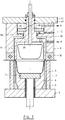
- FIGS. 1-4 each show a cross section through a mold cavity of a form-punching tool in four different embodiments.
- the form-punching tool in all 4 embodiments shown consists of two mold halves, the lower part 1 and the upper part 2.
- the lower part 1 is composed of a base plate 3, the cooling block 4, inserted punches 5, mold inserts 6 and bottoms 7 each an ejector rod 8 together.
- the arrangement of the individual mold cavities in the cooling block 4 can be single-row or multi-row. Each row can have several mold cavities.
- the upper part 2 has a cutting plate 10 mounted on the intermediate plate 9 and a head plate 11.
- the intermediate plate 9 and head plate 11 can, as shown in Figure 4, consist of one piece. Openings 12 are provided in the cutting plate 10 in accordance with the contour of the container 13 to be punched out.
- In each breakthrough 12 there is a pot-shaped hold-down device 14 which merges into a shaft 15 with several shoulders.
- holes 21 with a larger diameter than the openings 12 are arranged in the intermediate plate 9.
- a pot 22 is inserted into each bore 21 and held by a collar 23.
- the bottom of the pot 23 is designed as a collar 24 and has a bore 25 corresponding to the diameter of the shoulder 16.
- a seal 26 is provided at this point of contact.
- On the shoulder 16 of the shaft 15 sits a piston 27 which extends outwards to the bore 21 and carries a circumferential seal 28.
- the shoulder 17 of the shaft 15 protrudes through the head plate 11 and is fastened outside with a nut 29 which sits on the thread of the shoulder 18.
- a compression spring 30 is mounted between the head plate 11 and the piston 27 to support the hold-down force and to define the position of the hold-down device 14. Formed air can be conducted into the interior of the hold-down device 14 via bores 31, 32.
- Compressed air is guided to the top of the piston 27 via the bore 33.
- the resulting force is transmitted via the shoulder of the shoulder 16 to the hold-down device 14 and thus to its ring surface 35 facing the film web 34. This force is used to calibrate / crush / shape the clamped container edge.
- FIG. 2 A second embodiment of the form-punching tool is shown in FIG. 2.
- the intermediate plate 9 is provided on both sides with a bore 36, 37, the depth of which is coordinated so that a collar 38 remains, in the bore 39 of which the shoulder 16 of the hold-down device 14 is guided.
- a piston 42 slides in the bore 37, which is supported on the collar of the shoulder 16 and is prestressed by a compression spring 40.
- the hold-down force is generated by supplying compressed air through the bore 41 into the space between the piston 42 and the top plate 11.
- Figure 3 shows a modification of the form-punching tool according to Figure 2 in such a way that a collar 43 for guiding the shoulder 16 is formed in such a way that a pot 45 is inserted into a bore 44 in the intermediate plate 9, the bottom of which this fret 43 forms.
- This design has the advantage that the bores 36 and 44 can be machined from one side, that is, without the intermediate plate 9 having to be reclamped, so that there is no risk of eccentricity.
- FIGS. 1 to 3 have the disadvantage that not all parts of the hold-down device, including the high-pressure device, can be installed or removed from the parting plane when the tool is open.
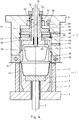
- the embodiment according to FIG. 4 avoids this disadvantage, so that maintenance and repair work are possible without having to dismantle the other parts of the tool.
- holes 46 with a smaller diameter than the openings 12 in the cutting plate 10 are provided in the intermediate plate 9.
- each bore 46 there is an annular piston 47, held on the one hand by a shoulder 48, on the other hand by a retaining ring 49 (FIG. 4 on the right) or held between two retaining rings 49 (FIG. 4 on the left).
- the solution with a shoulder 48 is followed by a slightly smaller diameter bore 50 in which a piston 51 is seated, which in the direction of the end of the shaft 15 merges into a shoulder 52 which extends as far as the stop nut 53 which sits on the shaft 15 .
- the piston 24 has an extension 63 which extends through the collar 24 to the shoulder 55 of the hold-down device 14.
- the piston 51 is acted upon by a compression spring 57, which thus presses the entire hold-down device 4 down until the stop nut 53 bears against the upper edge of the intermediate plate 9.
- Compressed air can be directed to the top of the piston 51 via bores 58, 59.
- a bore 61 is provided in the intermediate plate 9 for the supply of shaped air. Via a further bore 62, this reaches the inside of the hold-down device 14.
- a bore 60 serves to vent the space between the piston 51 and the annular piston 47.
- the tool is installed in the forming station of a thermoforming machine and works as follows: When the tool is open, a section of a heated film web 34 is transported between the two tool halves 1, 2 and this is closed to such an extent that the film web 34 is partially severed by the cutting punches 5.
- the hold-down devices 14 move back accordingly. For this purpose, only the force of the springs 25, 40, 57 must be overcome by the drive of the thermoforming machine. In this closed position, the compressed air is supplied through corresponding holes on the top of the piston 27, 42, 51, whereby the hold-down device 14 is pressed down. This forms the edge of the container.
- the supply of the shaped air and, if appropriate, the stretching aid insert takes place in a known manner, as a result of which the containers 13 are deformed.
- the compressed air for the hold-down force first escapes, so that the hold-down force is reduced when the lower die part 1 starts to punch. Then the mold air escapes, the tool opens and the shaped articles are transported out and stacked in a known manner.
Abstract
Description
Die Erfindung betrifft ein Form- Stanz-Werkzeug zum Herstellen von Behältern aus thermoplastischer Kunststoffolie nach der Gattung des Hauptanspruches.The invention relates to a form-punching tool for producing containers from thermoplastic plastic film according to the preamble of the main claim.
Ein solches Werkzeug ist aus der EP 0 525 483 A 1 bekannt. Bei diesem wird der Niederhalter, der als Ringkolben ausgebildet ist, mit Druckluft beaufschlagt, so daß die Kraft des Niederhalters in Abhängigkeit des Verfahrensablaufes gesteuert werden kann. So kann man beim Schließen des Werkzeuges zur Schonung des Antriebes keine Niederhalterkraft wirken lassen und erst bei geschlossenem Werkzeug oder beim Ausschieben des ausgestanzten Behälters beim Öffnen des Werkzeuges diese Niederhalterkraft aufbauen.Such a tool is known from EP 0 525 483 A1. In this case, the hold-down device, which is designed as an annular piston, is pressurized with compressed air, so that the force of the hold-down device can be controlled as a function of the process sequence. This means that when the tool is closed to protect the drive, no hold-down force can be applied and this hold-down force can only be built up when the tool is closed or when the punched-out container is pushed out when the tool is opened.
Wie man aus der genannten Schrift erkennen kann, wird die Formluft zum Ausformen der Behälter aus demselben Tank zugeführt wie die Druckluft zur Erzeugung der Niederhalterkraft. Die Formluft wirkt im Innern des geschlossenen Formwerkzeuges der Niederhalterkraft entgegen und hebt diese je nach maßlichen Verhältnissen mehr oder weniger auf oder diese wird sogar größer als die Niederhalterkraft. Dies spielt dann keine Rolle, wenn man die Niederhalterkraft nur zum Ausstoßen der geformten Behälter verwendet, denn beim Ausstoßen ist die Formluft bereits entlüftet.As can be seen from the cited document, the shaped air for molding the container is supplied from the same tank as the compressed air for generating the hold-down force. The shaped air counteracts the hold-down force inside the closed mold and, depending on the dimensional conditions, more or less abolishes it or it even becomes greater than the hold-down force. This is irrelevant if the hold-down force is only used to eject the molded container, because the molding air is already vented when it is ejected.
Es gibt Behälter, bei denen der zwischen dem Schnittstempel und dem Niederhalter eingespannte Behälterrand kalibriert bzw. verdünnt werden soll oder bei denen in diesen Rand ein Siegelwulst eingeformt werden soll. Dazu ist eine entsprechende Niederhalterkraft als Gegenkraft zur Schließkraft des Werkzeuges erforderlich. Um diese zu erzeugen, ist es bekannt, die Formluft und die Druckluft zur Niederhalterbeaufschlagung aus zweierlei Druckluftnetzen mit unterschiedlichen Drücken zu speisen. Da die Formluft bei den heute häufig eingesetzten PP-Folien in der Größenordnung von 6 bar liegen muß, ist es erforderlich, zur Erzielung einer ausreichenden Niederhalterkraft ein Druckluftnetz mit ca. 12 bis 16 bar aufzubauen. Dies erfordert eine eigene Hochdruck-Kompressor-Anlage, da Druckluftnetze in Fertigungsbetrieben in der Regel einen maximalen Druck von 8 bis 10 bar haben. Dadurch werden die Druckluftkosten entsprechend hoch, ein eigenes Druckluftnetz muß installiert werden.There are containers in which the edge of the container clamped between the cutting punch and the hold-down device is to be calibrated or thinned, or in which a sealing bead is to be molded into this edge. To this end, a corresponding hold-down force acts as a counterforce to the closing force of the Tools required. In order to generate this, it is known to feed the shaped air and the compressed air for pressurization from two types of compressed air networks with different pressures. Since the shaped air in the PP films frequently used today must be in the order of 6 bar, it is necessary to build up a compressed air network with approx. 12 to 16 bar in order to achieve a sufficient hold-down force. This requires a dedicated high-pressure compressor system, since compressed air networks in manufacturing plants generally have a maximum pressure of 8 to 10 bar. As a result, the compressed air costs are correspondingly high, a separate compressed air network must be installed.
Der Erfindung lag die Aufgabe zugrunde, das Werkzeug so zu gestalten, daß eine ausreichende Niederhalterkraft bei Verwendung von Druckluft mit einem Druck erzielt werden kann, der im wesentlichen dem Druck der Formluft entspricht. Spezielle Hochdruckerzeuger und -netze sollten nicht erforderlich sein. Die konstruktiven Maßnahmen sollten eine sichere und zuverlässige Wirkungsweise gewährleisten und kostenmäßig im Rahmen liegen.The invention had for its object to design the tool so that a sufficient hold-down force can be achieved when using compressed air with a pressure that corresponds essentially to the pressure of the molding air. Special high pressure generators and networks should not be required. The design measures should ensure a safe and reliable mode of operation and should be within the budget.
Gelöst ist diese Aufgabe erfindungsgemäß durch die im Kennzeichen des Hauptanspruches angegebenen Maßnahmen. Die Unteransprüche stellen vorteilhafte Aus- bzw. Weiterbildungen dar.This object is achieved according to the invention by the measures specified in the characterizing part of the main claim. The subclaims represent advantageous training and further education.
Ein Ausführungsbeispiel des Werkzeuges nach der Erfindung ist anhand der schematischen Zeichnung näher beschrieben. Es zeigen die Figur 1 - 4 jeweils einen Querschnitt durch ein Formnest eines Form-Stanz-Werkzeuges in vier verschiedenen Ausführungsformen.An embodiment of the tool according to the invention is described in more detail with reference to the schematic drawing. FIGS. 1-4 each show a cross section through a mold cavity of a form-punching tool in four different embodiments.
Das Form-Stanz-Werkzeug besteht in allen 4 gezeigten Ausführungsformen aus zwei Formhälften, dem Unterteil 1 und dem Oberteil 2. Dabei setzt sich das Unterteil 1 aus einer Grundplatte 3, dem Kühlblock 4, eingesetzen Schnittstempeln 5, Formeinsätzen 6 und Böden 7 mit je einer Auswerferstange 8 zusammen. Die Anordnung der einzelnen Formnester im Kühlblock 4 kann einreihig oder mehrreihig sein. Jede Reihe kann mehrere Formnester aufweisen. Das Oberteil 2 weist eine an der Zwischenplatte 9 montierte Schnittplatte 10 und eine Kopfplatte 11 auf. Zwischenplatte 9 und Kopfplatte 11 können, wie in Figur 4 dargestellt, aus einem Stück bestehen. In der Schnittplatte 10 sind Durchbrüche 12 entsprechend der auszustanzenden Kontur der Behälter 13 vorgesehen. In jedem Druchbruch 12 sitzt ein topfförmiger Niederhalter 14, der nach hinten in einen Schaft 15 mit mehreren Absätzen übergeht. Im Schaft 15 gleitet in einer zentralen Bohrung die Stange 19, die den Streckhelfer 20 trägt.The form-punching tool in all 4 embodiments shown consists of two mold halves, the
Gemäß einer ersten Ausführungsform nach Figur 1 sind in der Zwischenplatte 9 Bohrungen 21 mit größerem Durchmesser als die Durchbrüche 12 angeordnet. Ein Topf 22 ist in jede Bohrung 21 eingesetzt und durch einen Bund 23 gehalten. Der Boden des Topfes 23 ist als Bund 24 ausgebildet und weist eine Bohrung 25 auf entsprechend dem Durchmesser des Absatzes 16. Eine Dichtung 26 ist an dieser Berührungsstelle vorgesehen. Auf dem Absatz 16 des Schaftes 15 sitzt ein Kolben 27, der nach außen bis zur Bohrung 21 verläuft und eine umlaufende Dichtung 28 trägt. Der Absatz 17 des Schaftes 15 ragt durch die Kopfplatte 11 und wird außerhalb mit einer Mutter 29 befestigt, die auf dem Gewinde des Absatzes 18 sitzt.According to a first embodiment according to FIG. 1,
Zwischen Kopfplatte 11 und Kolben 27 ist eine Druckfeder 30 zur Unterstützung der Niederhalterkraft und zur Lagedefinition der Niederhalter 14 montiert. Über Bohrungen 31, 32 kann Formluft ins Innere des Niederhalters 14 geleitet werden.A
Über die Bohrung 33 wird Druckluft auf die Oberseite des Kolbens 27 geführt. Die dadurch entstehende Kraft wird über die Schulter des Absatzes 16 auf den Niederhalter 14 und damit auf seine der Folienbahn 34 zugewandte Ringfläche 35 übertragen. Diese Kraft dient der Kalibrierung/Quetschung/Formung des eingespannten Behälterrandes.Compressed air is guided to the top of the
Eine zweite Ausführungsform des Form-Stanz-Werkzeuges zeigt Figur 2. In diesem Fall ist die Zwischenplatte 9 von beiden Seiten mit einer Bohrung 36, 37 versehen, deren Tiefe so abgestimmt ist, daß ein Bund 38 stehen bleibt, in dessen Bohrung 39 der Absatz 16 des Niederhalters 14 geführt ist. In der Bohrung 37 gleitet ein Kolben 42, der sich am Bund des Absatzes 16 abstützt und von einer Druckfeder 40 vorgespannt wird. Durch Druckluftzufuhr durch die Bohrung 41 in den Raum zwischen Kolben 42 und Kopfplatte 11 wird die Niederhalterkraft erzeugt.A second embodiment of the form-punching tool is shown in FIG. 2. In this case, the
Figur 3 zeigt eine Abwandlung des Form-Stanz-Werkzeuges nach Figur 2 in der Weise, daß ein Bund 43 zur Führung des Absatzes 16 in der Weise gebildet wird, daß in eine Bohrung 44 in der Zwischenplatte 9 ein Topf 45 eingesetzt wird, dessen Boden diesen Bund 43 bildet. Diese Bauweise hat den Vorteil, daß die Bohrungen 36 und 44 von einer Seite her bearbeitet werden können, also ohne Umspannung der Zwischenplatte 9, sodaß keine Gefahr einer Exzentrizität besteht.Figure 3 shows a modification of the form-punching tool according to Figure 2 in such a way that a
Die Ausführungsformen gemäß den Figuren 1 bis 3 haben den Nachteil, daß nicht alle Teile des Niederhalters einschließlich Hochdruckeinrichtung bei geöffnetem Werkzeug von der Trennebene aus ein- bzw. ausgebaut werden können. Diesen Nachteil vermeidet die Ausführungsform gemäß Figur 4, so daß Wartungs- und Reparaturarbeiten möglich sind, ohne die anderen Teile des Werkzeuges demontieren zu müssen. Dazu sind in der Zwischenplatte 9 Bohrungen 46 mit kleinerem Durchmesser als die Durchbrüche 12 in der Schnittplatte 10 vorgesehen.The embodiments according to FIGS. 1 to 3 have the disadvantage that not all parts of the hold-down device, including the high-pressure device, can be installed or removed from the parting plane when the tool is open. The embodiment according to FIG. 4 avoids this disadvantage, so that maintenance and repair work are possible without having to dismantle the other parts of the tool. For this purpose,
In jeder Bohrung 46 sitzt ein Ringkolben 47, einerseits gehalten von einem Absatz 48, andererseits von einem Sicherungsring 49 (Fig. 4 rechts) oder gehalten zwischen zwei Sicherungsringen 49 (Fig. 4 links). Bei der Lösung mit einem Absatz 48 folgt eine im Durchmesser etwas kleinere Bohrung 50, in der ein Kolben 51 sitzt, der in Richtung des Endes des Schaftes 15 in einen Absatz 52 übergeht, der bis zur Anschlagmutter 53 reicht, die auf dem Schaft 15 sitzt.In each
Wird der Ringkolben 47 zwischen zwei Sicherungsringen 49 gehalten, sind die Bohrungen 46 und 50 gleich im Durchmesser. Bezüglich der Ausbildung des Kolbens 51 in Richtung Trennebene gibt es zwei Vorschläge. Gemäß Figur 4 links weist der Kolben 51 einen Absatz 54 auf, der durch den Ringkolben 47 ragt und sich auf der Schulter 55 des Niederhalters 14 abstützt. Figur 1 rechts zeigt, wie sich der Kolben 51 direkt auf einem Absatz 56 am Schaft 15 abstützt. Beide Lösungen haben ihre Vorteile.If the
Die gleiche Lösung ist in Figur 1 links dargestellt. Auch hier weist der Kolben 24 einen Ansatz 63 auf, der sich durch den Bund 24 bis zur Schulter 55 des Niederhalters 14 erstreckt.The same solution is shown on the left in FIG. 1. Here, too, the
Der Kolben 51 wird von einer Druckfeder 57 beaufschlagt, die damit den ganzen Niederhalter 4 nach unten drückt, bis die Anschlagmutter 53 an der Oberkante der Zwischenplatte 9 anliegt. Über Bohrungen 58, 59 kann Druckluft auf die Oberseite des Kolbens 51 geleitet werden. Zur Formluftzufuhr ist eine Bohrung 61 in der Zwischenplatte 9 vorgesehen. Über eine weitere Bohrung 62 gelangt diese ins Innere des Niederhalters 14. Eine Bohrung 60 dient der Entlüftung des Raumes zwischen Kolben 51 und Ringkolben 47.The
Das Werkzeug wird in die Formstation einer Thermoformmaschine eingebaut und arbeitet wie folgt:
Bei geöffnetem Werkzeug wird ein Abschnitt einer erwärmten Folienbahn 34 zwischen die beiden Werkzeughälften 1, 2 transportiert und dieses soweit geschlossen, daß die Folienbahn 34 teilweise von den Schnittstempeln 5 durchtrennt wird. Die Niederhalter 14 weichen entsprechend zurück. Hierzu muß vom Antrieb der Thermoformmaschine nur die Kraft der Federn 25, 40, 57 überwunden werden. In dieser geschlossenen Stellung erfolgt die Druckluftzufuhr über entsprechende Bohrungen auf die Oberseite des Kolbens 27, 42, 51 wodurch der Niederhalter 14 nach unten gedrückt wird. Hierdurch wird der Behälterrand geformt. Gleichzeitig erfolgt die Zufuhr der Formluft und ggf. der Streckhelfereinsatz in bekannter Weise, wodurch die Behälter 13 verformt werden. Jetzt entweicht zunächst die Druckluft für die Niederhalterkraft, damit bei der nun einsetzenden Stanzbewegung des Werkzeugunterteils 1 die Niederhalterkraft abgebaut ist. Dann entweicht die Formluft, das Werkzeug öffnet und die geformten Artikel werden in bekannter Weise austransportiert und gestapelt.The tool is installed in the forming station of a thermoforming machine and works as follows:
When the tool is open, a section of a
Bei geöffnetem Werkzeug ist es bei der Ausführung nach Fig. 4 möglich, nach der Demontage der Streckhelfer 20 und dem Entfernen der Anschlagmutter 53 den Niederhalter 14 zur Trennebene hin herauszuziehen. Damit wird der Sicherungsring 49 zugänglich. Nach seiner Entfernung können Ringkolben 47 und Kolben 51 einschließlich Druckfeder 57 zur Trennebene hin entfernt werden. Der Austausch sämtlicher Dichtungen ist möglich. Es ist nicht erforderlich, die Schnittplatte 10 zu entfernen, um diese Zugänglichkeit zu erzielen.With the tool open, it is possible in the embodiment according to FIG. 4 to pull out the hold-down
Claims (13)
Applications Claiming Priority (4)
| Application Number | Priority Date | Filing Date | Title |
|---|---|---|---|
| DE4421979 | 1994-06-23 | ||
| DE19944421979 DE4421979C1 (en) | 1994-06-23 | 1994-06-23 | Thermo-forming and cutting tool for prodn. of containers from thermoplastic film |
| DE19944445376 DE4445376C1 (en) | 1994-12-20 | 1994-12-20 | Punching tool for containers produced in thermoplastic film |
| DE4445376 | 1994-12-20 |
Publications (2)
| Publication Number | Publication Date |
|---|---|
| EP0688659A2 true EP0688659A2 (en) | 1995-12-27 |
| EP0688659A3 EP0688659A3 (en) | 1997-10-08 |
Family
ID=25937664
Family Applications (1)
| Application Number | Title | Priority Date | Filing Date |
|---|---|---|---|
| EP95108966A Withdrawn EP0688659A3 (en) | 1994-06-23 | 1995-06-10 | Forming and punching tool for producing thermoplastic containers |
Country Status (1)
| Country | Link |
|---|---|
| EP (1) | EP0688659A3 (en) |
Cited By (3)
| Publication number | Priority date | Publication date | Assignee | Title |
|---|---|---|---|---|
| DE19958065A1 (en) * | 1999-12-02 | 2001-06-28 | Optipack Gmbh & Co Kg | Device for deep-drawing cup-shaped bodies |
| EP1377919A2 (en) * | 2000-07-24 | 2004-01-07 | PACT XPP Technologies AG | Integrated circuit |
| DE202011001622U1 (en) * | 2011-01-17 | 2012-04-18 | Gizeh Verpackungen Gmbh & Co. Kg | Compressed gas thermoforming apparatus |
Citations (1)
| Publication number | Priority date | Publication date | Assignee | Title |
|---|---|---|---|---|
| EP0525483A1 (en) | 1991-07-27 | 1993-02-03 | Verpaco Ag | Apparatus for the production of plastic cups |
Family Cites Families (3)
| Publication number | Priority date | Publication date | Assignee | Title |
|---|---|---|---|---|
| DE2145250A1 (en) * | 1971-09-10 | 1973-03-15 | Wilhelm Anton Haeberle | Deep drawn containers - of thermoplastic shaped plastic foil/sheet |
| DE3936891A1 (en) * | 1989-11-06 | 1991-05-08 | Illig Maschinenbau Adolf | Deep-draw tool for beaker mfr. from thermoplastic film - in which clamping rings are attached to crossbar on whose ends are bars which contact stops on lower tool half |
| DE4326190A1 (en) * | 1993-08-04 | 1995-02-09 | Marbach Werkzeugbau Gmbh | Thermoforming mould |
-
1995
- 1995-06-10 EP EP95108966A patent/EP0688659A3/en not_active Withdrawn
Patent Citations (1)
| Publication number | Priority date | Publication date | Assignee | Title |
|---|---|---|---|---|
| EP0525483A1 (en) | 1991-07-27 | 1993-02-03 | Verpaco Ag | Apparatus for the production of plastic cups |
Cited By (4)
| Publication number | Priority date | Publication date | Assignee | Title |
|---|---|---|---|---|
| DE19958065A1 (en) * | 1999-12-02 | 2001-06-28 | Optipack Gmbh & Co Kg | Device for deep-drawing cup-shaped bodies |
| DE19958065C2 (en) * | 1999-12-02 | 2001-12-06 | Optipack Gmbh & Co Kg | Device for deep-drawing cup-shaped bodies |
| EP1377919A2 (en) * | 2000-07-24 | 2004-01-07 | PACT XPP Technologies AG | Integrated circuit |
| DE202011001622U1 (en) * | 2011-01-17 | 2012-04-18 | Gizeh Verpackungen Gmbh & Co. Kg | Compressed gas thermoforming apparatus |
Also Published As
| Publication number | Publication date |
|---|---|
| EP0688659A3 (en) | 1997-10-08 |
Similar Documents
| Publication | Publication Date | Title |
|---|---|---|
| DE4322063C2 (en) | Method and device for cutting out a section of a wall of a hollow body produced by the hydroforming process | |
| DE10030010C2 (en) | Process for producing a container from a thermoplastic film and mold for carrying out the process | |
| DE3931320C1 (en) | ||
| DE19506067C1 (en) | Aperture cutter for pressure moulded items | |
| EP2999582B1 (en) | Tool, tool station, thermoforming system and method for operating a thermoforming system | |
| DE2752594A1 (en) | DEVICE FOR PUNCHING AND DEEP DRAWING OF WORKPIECES FROM SHEET METAL OR DGL. | |
| EP1582333B1 (en) | Method and apparatus for thermoforming and cutting out containers from a thermoplastic sheet | |
| EP0845312B1 (en) | Flexibly applicable die for high pressure forming | |
| EP0688659A2 (en) | Forming and punching tool for producing thermoplastic containers | |
| DE102007011292B4 (en) | Mold for applying a label to a deep-drawn molding and method for operating the mold | |
| DE19805275A1 (en) | Wall breakthrough production | |
| DE4421979C1 (en) | Thermo-forming and cutting tool for prodn. of containers from thermoplastic film | |
| DE19948768C1 (en) | Assembly, to mold and stamp out containers of thermoplastic film, has common drive for the molding and stamping units with stamping movements independent of the mold closing actions | |
| DE4445376C1 (en) | Punching tool for containers produced in thermoplastic film | |
| EP2052843B1 (en) | Method for operating a device for manufacturing shaped pieces made of thermoplastic material | |
| DE19911125C1 (en) | Workpiece cutting/perforation forms a pressure zone with a pressure medium on one side with a cutting edge and a spaced auxiliary cutting edge on the other workpiece side giving cut edges with low distortion and small flash height | |
| DE19532571C1 (en) | Thermo-forming tool for mfg. containers in thermoplastic film | |
| EP0525483A1 (en) | Apparatus for the production of plastic cups | |
| DE102004012858B4 (en) | Roller body manufacturing method for roller bearing, involves measuring weight or volume of raw blocks, and feeding blocks in to pressing tool, where blocks are shaped in tool in two stages and deformed by stamp that penetrates in to tool | |
| EP1344628A1 (en) | Apparatus for deep drawing of plastic containers and method for using the deep drawing apparatus | |
| EP0561310A1 (en) | Apparatus for cold-deforming of plastic sheets, in particular polypropylene sheets of different thickness | |
| DE10218511B4 (en) | Thermoforming plant for the production of moldings made of plastic film, and process for their preparation | |
| DE2417270A1 (en) | METHOD AND DEVICE FOR HEAT FORMING OF THIN-WALLED CONTAINERS MADE OF PLASTIC | |
| DE2931715C2 (en) | Molding tool for the production of membranes | |
| DE2214361A1 (en) | Rim formation on plastic cups - by pressing together plastic resin rim portion before moulding cup |
Legal Events
| Date | Code | Title | Description |
|---|---|---|---|
| PUAI | Public reference made under article 153(3) epc to a published international application that has entered the european phase |
Free format text: ORIGINAL CODE: 0009012 |
|
| AK | Designated contracting states |
Kind code of ref document: A2 Designated state(s): CH DE FR GB IT LI NL |
|
| PUAL | Search report despatched |
Free format text: ORIGINAL CODE: 0009013 |
|
| AK | Designated contracting states |
Kind code of ref document: A3 Designated state(s): CH DE FR GB IT LI NL |
|
| 17P | Request for examination filed |
Effective date: 19970829 |
|
| 17Q | First examination report despatched |
Effective date: 19990427 |
|
| STAA | Information on the status of an ep patent application or granted ep patent |
Free format text: STATUS: THE APPLICATION HAS BEEN WITHDRAWN |
|
| 18W | Application withdrawn |
Withdrawal date: 19990814 |