EP0687885B1 - Fahrzeug-selbstverteidigungssystem - Google Patents
Fahrzeug-selbstverteidigungssystem Download PDFInfo
- Publication number
- EP0687885B1 EP0687885B1 EP94903183A EP94903183A EP0687885B1 EP 0687885 B1 EP0687885 B1 EP 0687885B1 EP 94903183 A EP94903183 A EP 94903183A EP 94903183 A EP94903183 A EP 94903183A EP 0687885 B1 EP0687885 B1 EP 0687885B1
- Authority
- EP
- European Patent Office
- Prior art keywords
- input
- output
- round
- ejection
- generation
- Prior art date
- Legal status (The legal status is an assumption and is not a legal conclusion. Google has not performed a legal analysis and makes no representation as to the accuracy of the status listed.)
- Expired - Lifetime
Links
Images


Classifications
-
- F—MECHANICAL ENGINEERING; LIGHTING; HEATING; WEAPONS; BLASTING
- F42—AMMUNITION; BLASTING
- F42B—EXPLOSIVE CHARGES, e.g. FOR BLASTING, FIREWORKS, AMMUNITION
- F42B12/00—Projectiles, missiles or mines characterised by the warhead, the intended effect, or the material
- F42B12/02—Projectiles, missiles or mines characterised by the warhead, the intended effect, or the material characterised by the warhead or the intended effect
- F42B12/20—Projectiles, missiles or mines characterised by the warhead, the intended effect, or the material characterised by the warhead or the intended effect of high-explosive type
- F42B12/22—Projectiles, missiles or mines characterised by the warhead, the intended effect, or the material characterised by the warhead or the intended effect of high-explosive type with fragmentation-hull construction
- F42B12/32—Projectiles, missiles or mines characterised by the warhead, the intended effect, or the material characterised by the warhead or the intended effect of high-explosive type with fragmentation-hull construction the hull or case comprising a plurality of discrete bodies, e.g. steel balls, embedded therein or disposed around the explosive charge
-
- F—MECHANICAL ENGINEERING; LIGHTING; HEATING; WEAPONS; BLASTING
- F41—WEAPONS
- F41H—ARMOUR; ARMOURED TURRETS; ARMOURED OR ARMED VEHICLES; MEANS OF ATTACK OR DEFENCE, e.g. CAMOUFLAGE, IN GENERAL
- F41H11/00—Defence installations; Defence devices
- F41H11/02—Anti-aircraft or anti-guided missile or anti-torpedo defence installations or systems
-
- G—PHYSICS
- G01—MEASURING; TESTING
- G01S—RADIO DIRECTION-FINDING; RADIO NAVIGATION; DETERMINING DISTANCE OR VELOCITY BY USE OF RADIO WAVES; LOCATING OR PRESENCE-DETECTING BY USE OF THE REFLECTION OR RERADIATION OF RADIO WAVES; ANALOGOUS ARRANGEMENTS USING OTHER WAVES
- G01S13/00—Systems using the reflection or reradiation of radio waves, e.g. radar systems; Analogous systems using reflection or reradiation of waves whose nature or wavelength is irrelevant or unspecified
- G01S13/02—Systems using reflection of radio waves, e.g. primary radar systems; Analogous systems
- G01S13/50—Systems of measurement based on relative movement of target
- G01S13/58—Velocity or trajectory determination systems; Sense-of-movement determination systems
- G01S13/583—Velocity or trajectory determination systems; Sense-of-movement determination systems using transmission of continuous unmodulated waves, amplitude-, frequency-, or phase-modulated waves and based upon the Doppler effect resulting from movement of targets
Definitions
- the invention relates to the field of the pieces of ordnance mounted on the carrier.
- the pieces of ordnance of this type provide self-defence for the carriers preferably the tanks.
- the tank self-defence system of Marconi comprises two machine-guns, a stationary cm-wavelength search radar and a guidance radar derived from the Thin-wavelength seeker of the HELLFIRE missile.
- the search radar transmits the acquisition signal of the attacking munition to the guidance radar and under the latter's control fire is automatically triggered to defeat antitank guided missiles and other low-velocity munitions.
- the system is not efficient enough in self-defence against attacking munitions incoming at a more higher velocity.
- a system according to the preamble part of claim 1 is known from DE-A- 34 10.4.67.
- the multi-barreled artillery piece provides self-defence for the carriers generally the tanks. It comprises a rotating platform mounted onto the tank turret with barrels being radially arranged to provide the all-round tank defence.
- the center platform part mounts the radar to acquire the attacking munition.
- a further object of the invention is to provide a system with a relatively small kill envelope not dangerous to the neighbouring hardware situated in immediate proximity to the carrier protected.
- the nature of the system proposed is that an arrangement of launch pits is placed around the tank turret providing the all-round defence of the tank.
- Each of the launch pits is of a rectangular section and inclined preferably at an angle of 25-40 deg. to a vertical tank axis.
- the launch pit is outfitted with a round comprising a box-type case, a propelling charge, a communication and an antiprojectile.
- the antiprojectile consists of a box-type body made from a non-metallic material, a fragmentation plate-type charge, a fragmentation lining to generate a directional fragment field.
- the antiprojectile is outfitted with a correction pulse engine to turn the antiprojectile.
- the correction engine is coupled via the communication line to a block for round selection and round ejection and antiprojectile detonation command generation.
- a radar range meter comprises a first master oscillator connected to a modulating signal generator, a first output thereof is connected to a first input of a transmitter signal modulator, a second input thereof is connected to a power amplifier with an input of the latter connected to a first output of a second master oscillator, an output of the transmitter signal modulator is connected to a transmitting antenna , a second output of the modulating signal generator is connected to an input of a delayed modulating signal generator, an output thereof is connected to a first input of a local oscillator signal modulator with a second input of the latter connected to an output of a first frequency converter, a first input thereof is connected to a second output of a second master oscillator and a second input is connected to an output of a third master oscillator, an output of the local oscillator signal modulator is connected to a power divider with the latter's first output connected to a first input of a second frequency converter of a reference channel, a second input thereof is connected to a
- the carrier self-defence system claimed is provided with a block to predict the entry of the attacking munition into the system's kill envelope, the block comprises a meter to measure a phase difference between the signals of reference and measurement channels, an output of the meter is connected to a first input of a generalized coordinates determination device, a first output thereof is connected to a first input of a calculator of a flight time of the attacking munition to a calculated boundary of the kill envelope, a second output is connected to a storage register of a preceding coordinate and to a first input of a comparison circuit, a second input thereof is connected to an output of the storage register of the preceding coordinate, an output of the comparison circuit is connected to a first input of a round number determination device with the latter's second input connected to a first output of the calculator of the flight time of the attacking munition to the calculated boundary of the kill envelope, a second input thereof is connected to a Doppler frequency meter, and its second output is connected to a first gate and to an input of
- the self-defence system claimed also contains the block for round selection and generation of ejection and detonation command comprising an analyzer of a pulse train passage sequence, a first input thereof is connected to the round number determination device and a second input to outputs of both the first time counter of generation of the round ejection command and the second time counter of generation of the antiprojectile detonation command, and an output thereof is connected to a timer input with the latter's output connected to third and fourth gates coupled to reservoir capacitors which are connected to anodes of first thyristors, the former of the two is controlled by a first shaper of the round ejection pulse and the latter by a second shaper of the antiprojectile detonation pulse, cathodes of the first thyristors are connected to anodes of second thyristors and to anodes of third thyristors controlled by a round number decoder, an input thereof is connected to the round number determination device, cathodes of the second th
- the self-defence system claimed allows to provide the effective all-round protection of the carrier against munitions fire within a wide range of their flight velocities.
- An inclination of the launch pits of 25-40 deg. to the vertical axis of the carrier provides a conical kill zone of small size.
- the box-type shape of the antiprojectile with a fragmentation charge formed as a plate provides a powerful flat-topped detonation wave propagating into a desired direction.
- the antiprojectile is initiated at a minimum safe distance from the tank thus providing a high system reaction.
- the range meter provides a high radar resolution, improved resistance to active jamming and natural noises.
- Said block selects tank-harmless targets and reduces the false operation probability.
- the random ejection and detonation signals are blocked at output by the analyzer of the pulse train passage sequence within the block for round selection and generation of its ejection and detonation command.
- a shower of killing fragments propelled is directed to an intercept point predicted thus enhancing a munition intercept ratio or decreasing the total round load and weight of the system.
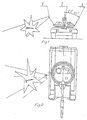
- Fig.1,2 are front and top views of a system configured on a tank turret.
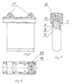
- Fig.3, 4, 5 are three projections of a round in a launch pit.
- Fig.6, 7, 8 are three projections of the round with built-in antiprojectile turning engine.
- Fig.9, 10 are front and top views of a system configuration with correction-capable rounds on the tank turret.
- Fig.11 is a functional diagram of a radar with a range meter.
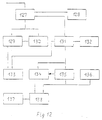
- Fig.12 is a functional diagram of a prediction block of an entry of an attacking munition to a system's kill envelope.
- Fig.13 is a functional diagram of a block for round selection and generation of its ejection and detonation command.
- Launch pits 3 with self-defence system rounds are evenly spaced round a periphery of a tank turret and provide an all-round tank defence.
- a tank top mounts a radar 2.
- Each round comprises an antiprojectile 1, a case 4 of rectangular cross-section, a propelling powder charge 5 and a wire communication assembly 6.
- the antiprojectile 1 consists of a plastic housing 7, a shaped fragment lining 8, a fragmentation charge 9 and a fuze 10 for detonation.
- the case 4 integrates the round as a complete hermetically sealed assembly and protects a launch pit hole against damage, dirt, moisture after round ejection.
- the propelling powder charge 5 ejects the antiprojectile 1 to a minimum distance of its safe initiation.
- Said charge 5 comprises a cylindrical gas-generator housing 11 with nozzle holes 12 carrying the powder charge inside.
- An electric igniter 13 is placed on one of its ends.
- the wire communication assembly 6 conducts electric pulses through the wire to the electric igniter 13 of the propelling powder charge 5 and to the fuze 10.
- the wire communication line is constructed as a flat coil 14.
- the case flange also incorporates an electric connector 15 to couple the round to a control system harness.
- a protective cover 16 is placed on top of the round. Each round is put into the launch pit of rectangular cross-section, a front pit wall protects against flat-trajectory fire.
- a top of the round can house four correction pulse engines 17 with detonators 18, powder charges 19 and ejectable pieces 20 to turn an in-flight antiprojectile 1 about its own center of mass through a calculated angle after ignition of two spaced powder charges 19 at a specific time point and ejection of pieces 20 accomplished on instruction of the block for round selection and generation of its ejection and detonation command (refer to Fig.6 through 11).
- the control system of said means includes a radar 2 with a range meter, prediction block of entry of the attacking munition to the self-defence system's kill envelope and a block for round selection and generation of its ejection and detonation command.
- Fig.11 explains the operation of the range meter of the radar 2.
- a carrier signal from a master oscillator 103 arrives through a power amplifier 102 to a modulator 101 of a transmitter signal.
- Said modulator 101 modulates the carrier signal with a signal coming from a modulating signal generator 107.
- An output signal of the modulator 101 of the transmitter signal is emitted via an antenna A1 into the open space.
- the signal issued by the modulating signal generator 107 arrives at the same time to both the modulator 101 of the transmitter signal and to a delayed modulating signal generator 111, said delay is varied by means of applying a signal of an estimated detection zone number of the attacking munition from a memory block 106 to an input of said generator.
- the delayed modulating signal is conducted to a signal shaper of a first local oscillator.
- the signal shaper of the first local oscillator comprises a frequency converter 104, a modulator 105 and a power divider 110.
- the carrier signal from the master oscillator 103 is applied to a first input of the frequency converter 104 and a second input receives a signal of a first intermediate frequency from a master oscillator 109, an output signal from the frequency converter 104 comes to a first input of the modulator 105, a second input thereof receives the modulating delayed signal.
- the signal of the first local oscillator comes from a modulator 105 output via the power divider 110 to first frequency convertors 112, 113 of reference and measurement channels.
- Both the reference and measurement channels of the radar have the same components.
- a signal from the receiving antenna A2 comes to a first input of the frequency convertor 112 and at its second input arrives a signal from the divider 110 of the first local oscillator. From an output of the frequency convertor 112 a signal on a frequency equal to a value difference between an intermediate frequency and a Doppler frequency of the attacking munition enters a filter 113 to prefiltrate signals returned from the attacking munition.
- a signal from the filter 113 output comes to an amplifier 114 and from the latter's output to a first input of a frequency convertor 115, a second input thereof receives a signal from a second local oscillator.
- an output signal of the filter 113 arrives at a first input of a frequency, convertor 123, a second input thereof receives a signal of a first intermediate frequency from the master oscillator 109, to a third input thereof is applied a signal from a master oscillator 122.
- a Doppler frequency signal containing information on a velocity comes via Doppler selection filter 125 to a Doppler frequency meter 132 and to a range signal shaper 126, an output signal thereof enters a device 127 of the generalized coordinates determination.
- the signal comes via a power divider 124 to second inputs of the frequency convertors 115, 120 of the reference and measurement reception channels.
- From outputs of the frequency convertors 115, 120 a signal on a frequency equal in value to that of a second intermediate frequency comes via amplifiers 116, 121 to a first input of a phase difference meter 128 of the prediction block.
- the operation of the measurement reception channel is analogous with that of the reference reception channel with an output signal thereof being applied to a second input of the phase difference meter 128.
- a phase difference between the reference and measurement reception channels contains information on angular trajectory parameters of the attacking munition.
- the prediction block of entry of the attacking munition into a system's kill envelope (Fig.12) has the device 127 of generaiized coordinates determination, a first input thereof receives a phase difference code and a second input thereof an attacking munition range code. Said device converts the codes of electrical values of the trajectory parameters to space codes of generalized coordinates.
- a first output signal of the device 127 of generalized coordinates determination comes to a first input of a calculator 131 of flight time of the attacking munition to an estimated kill envelope boundary, a Doppler frequency code is applied to its second input from a Doppler frequency meter 132.
- the calculator 131 calculates the flight time of the attacking munition to the estimated kill envelope boundary, a code of said time is entered into a controlled counter 134 of an ejection time command and to a second input of a round number determination device 133.
- a code enters a preceding coordinate storage register 130 and a comparison circuit 129.
- the comparison circuit 129 compares the code values, the difference between the code values comes to an input of the round number determination device 133.
- Said device multiplying the difference value of the codes of the generalized coordinates by a factor determined by the flight time of the attacking munition to the estimated kill envelope determines the defensive round number and generates a defensive round selection signal that enters the generation block of ejection and detonation command.
- Gate 135 issues pulses from a master oscillator 136 to read the code of the calculated flight time of the attacking munition to the kill envelope.
- contents reset an instruction is generated to eject the antiprojectile and another instruction is issued to put in operation a gate 138, simultaneously a reading starts of contents of a detonation command time counter 137 by pulses from the master oscillator 137.
- the detonation command is generated. Duration of the ejection and detonation commands is set.
- the generation block (Fig.13) of the ejection and detonation command has an analyzer 142 of a passage sequence of defensive round number code pulses. Missing the round number code generates an instruction to start a timer 143, a count time thereof is set and determined by a maximum possible time of presence of the attacking munition in a service area of the radar 2. A wrong sequence of the pulse train passage cancels starting the timer 143 and gates 145 and 144 are cut off, reservoir capacitors C1 and C2 are discharged by means of resistors R1 and R2 respectively.
- a decoder 139 At the output of a decoder 139 the signals are formed that are required to control the operation of thyristors V11, V12 ... V1n and V21, V22 ... V2n with turning on the specific thyristor pairs dependent on the code of the selected round number.
- the thyristors V11, V12 ... V1n and V21, V22 ... V2n are connected by an AND logic.
- the reservoir capacitor C1 is discharged to an igniter selected at a simultaneous presence of both the ejection pulse and the defensive round number pulse
- the reservoir capacitor C2 is discharged to a detonator selected at a simultaneous presence of both the detonation pulse and the round number pulse.
- the system operates as follows:
- the radar input signal comes to the prediction block of entry of the attacking munition to the system's kill envelope.
- the prediction block analyzes the signals received and switches the radar 2 to the measurement mode. Information on the attacking munition parameters (range, velocity, azimuth, elevation) are fed back to the prediction block. While measuring the prediction block controls the radar operation and calculates, from the data obtained during measurement, the entrance point of the attacking munition to the system's kill envelope.
- the radar 2 switches to the search mode. If the attacking munition trajectory hits within the tank outline so the required round is selected and a command is generated to eject it.
- the electric pulse from the block for round selection and generation of its ejection and detonation command is conducted through the wire line 6 to the igniter followed by the ignition of the powder charge 5 of the gas generator, through the nozzle exits thereof the exhaust flows into the behind-the-antiprojectile space.
- the starting movement of the antiprojectile 1 interrupts the control circuit of the presence of the round in the launch pit and the unreeling of the microcable of the communication assembly 6 sets in.
- the g-load removes the fuze safety barrier, arms the fuze 10.
- the prediction block determines the time of entering the attacking munition to the kill envelope more precisely and calculates the antiprojectile detonation time followed by the detonation command generation.
- the block for round selection and generation of its ejection and detonation command generates, following the antiprojectile ejection, additionally an electric pulse at a specific time point through the wire line to initiate the correction engine charges, thus by the detonation time making the antiprojectile 1 to turn to the predicted entry point of the attacking munition to the kill envelope of the self-defence system.
- the detonation of the antiprojectile 1 produces the directional high-energy fragment shower, its hitting the attacking munition causes the latter's detonation in flight or reduces its action against the armour to the level not dangerous to the carrier. After the round ejection the launch pit holds the case that serves to protect it and the connector against dirt and moisture.
- the tanks equipped with the system proposed feature the combat survivability enhanced by a factor of 1.5 to 2.
- the effectiveness and functionability of the system claimed are verified by manufacture and trials of the brassboard models.
Landscapes
- Engineering & Computer Science (AREA)
- General Engineering & Computer Science (AREA)
- Aviation & Aerospace Engineering (AREA)
- Radar, Positioning & Navigation (AREA)
- Remote Sensing (AREA)
- Chemical & Material Sciences (AREA)
- Combustion & Propulsion (AREA)
- Aiming, Guidance, Guns With A Light Source, Armor, Camouflage, And Targets (AREA)
- Nitrogen And Oxygen Or Sulfur-Condensed Heterocyclic Ring Systems (AREA)
- Radar Systems Or Details Thereof (AREA)
Claims (5)
- Ein Fahrzeug-Selbstverteidigungssystem, z.B. eines Panzers, welches eine Radarstation (2) zur Entdeckung und Messung der Flugbahnparameter eines angreifenden Geschosses und sich auf Oberteilen des Fahrzeugs befindende und die Rundumverteidigung bildende Munitionseinheiten hat, wobei jede Munitionseinheit in einem Startgerät (3) untergebracht ist und eine Treibladung (5) und ein Gegengeschoß (1) aufweist, dadurch gekennzeichnet, daß es ausgestattet mit einer Einheit zur Voraussage des Einflugs des angreifenden Geschosses in die Bekämpfungszone des Selbstverteidigungssystems, einer Einheit zur Auswahl einer Munitionseinheit und Befehlsausgabe für deren Ausstoß und Detonation ist, wobei die Munitionseinheit in einem Startschacht (3) eines rechteckigen Querschnitts untergebracht ist, der schräg, vorzugsweise beim Winkel von 25° bis 40° zur senkrechten Achse des Fahrzeugs, gestellt ist, und ein Gegengeschoß (1) ein Kastengehäuse (4), vorzugsweise aus nichtmetallischem Werkstoff, hat, welches eine Sprengladung (9) in der Form einer Platte, einen Splitterbelag (8) einschließt, der ein gerichtetes Splitterfeld erzeugt, wobei ein Zünder (10) über eine Verbindungsleitung (6) an die Einheit zur Auswahl einer Munitionseinheit und Befehlsausgabe für deren Ausstoß und Detonation angeschlossen ist.
- Ein Fahrzeug-Selbstverteidigungssystem nach Anspruch 1, dadurch gekennzeichnet, daß ein Entfernungsmesser einer Radarstation (2) einen ersten Steuergenerator (108) hat, welches an einen Modulationssignalgenerator (107) angeschlossen ist, wobei dessen erster Ausgang mit einem ersten Eingang eines Sendersignalmodulators (101), dessen zweiter Eingang mit einem Leistungsverstärker (102) verbunden ist, wobei dessen Eingang an einen ersten Ausgang eines zweiten Steuergenerators (103) angeschlossen ist, ein Ausgang des Sendersignalmodulators (101) mit einer Sendeantenne (A1) verbunden ist, ein zweiter Ausgang des Modulationssignalgenerators (107) an einen Eingang eines Modulationssignalgenerators mit Verzögerung (111) geschaltet ist, dessen Ausgang an einen ersten Eingang eines Überlagerersignalmodulators (105) angeschlossen ist, dessen zweiter Eingang mit einem Ausgang eines ersten Frequenzwandlers (104) verbunden ist, wobei sein erster Eingang an einen zweiten Ausgang des zweiten Steuergenerators (103) und zweiter Eingang an einen Ausgang eines dritten Steuergenerators (109) geschaltet ist, wobei ein Ausgang des Überlagerersignalmodulators (105) an einen Leistungsverteiler (110) angeschlossen ist, dessen erster Ausgang an einen ersten Eingang eines zweiten Frequenzwandlers (112) eines Referenzkanals und sein zweiter Ausgang an eine erste Empfangsantenne (A2) angeschlossen ist, ein zweiter Ausgang des Leistungsverteilers (110) an einen ersten Eingang eines dritten Frequenzwandlers (117) eines Meßkanals geschaltet ist, dessen zweiter Eingang mit einer zweiten Empfangsantenne (A3) verbunden ist, ein zweiter Eingang des Modulationssignalgenerators mit Verzögerung (111) an eine Einheit (106) zur Speicherung von Berechnungsbereichen der Entdeckung eines angreifenden Geschosses geschaltet ist.
- Ein Fahrzeug-Selbstverteidigungssystem nach einem der Ansprüche 1, 2, dadurch gekennzeichnet, daß eine Einheit zur Voraussage des Einflugs eines angreifenden Geschosses in die Bekämpfungszone des Selbstverteidigungssystems einen Messer (128) der Phasendifferenz zwischen Referenz- und Meßkanalsignalen aufweist, dessen Ausgang einem ersten Eingang einer Einrichtung zur Berechnung der verallgemeinerten Koordinaten (127) zugeschaltet ist, deren erster Ausgang an einen ersten Eingang eines Rechners (131) der Flugzeit des angreifenden Geschosses bis zur Berechnungsgrenze der Bekämpfungszone und sein zweiter Ausgang an ein Speicherungsregister (130) der vorangegangenen Koordinate sowie an einen ersten Eingang einer Vergleichsschaltung (129) geschaltet ist, deren zweiter Eingang an einen Ausgang des Speicherungsregisters (130) der vorangegangenen Koordinate und ihr Ausgang an einen ersten Eingang einer Einrichtung zur Munitionsnummerbestimmung (133) angeschlossen ist, deren zweiter Eingang mit einem ersten Ausgang des Rechners (131) der Flugzeit des angreifenden Geschosses bis zur Berechnungsgrenze der Bekämpfungszone verbunden ist, dessen zweiter Eingang einem Doppler-Frequenzmesser (132) und sein zweiter Ausgang einem ersten Schalter sowie einem Eingang eines ersten gesteuerten Zeitzähler (134) der Ausgabe eines Befehls zum Munitionsausstoß zugeschaltet ist, ein zweiter Eingang des ersten Schalters (135) einem Ausgang eines vierten Steuergenerators (136) und ein Ausgang des ersten Schalters (135) einem zweiten Eingang des ersten gesteuerten Zeitzählers (134) der Ausgabe eines Befehls zum Munitionsausstoß zugeschaltet ist, dessen Ausgang an einen ersten Eingang eines zweiten Schalters (138) angeschlossen ist, dessen zweiter Eingang einem Ausgang des vierten Steuergenerators (136) und ein Ausgang des zweiten Schalters (138) einem zweiten gesteuerten Zeitzähler (137) der Ausgabe eines Befehls zur Gegengeschoßdetonation zugeschaltet ist.
- Ein Fahrzeug-Selbstverteidigungssystem nach Ansprüchen 1, 2, 3, dadurch gekennzeichnet, daß eine Einheit zur Auswahl einer Munitionseinheit und der Ausgabe eines Befehls für deren Ausstoß und Detonation einen Analysator (142) einer Impulsfolge aufweist, dessen erster Eingang an eine Einrichtung zur Munitionsnummerbestimmung (133), ein zweiter Eingang an Ausgänge eines ersten Zeitzählers der Ausgabe eines Befehls zum Munitionsausstoß (134) und eines zweiten Zeitzählers zur Gegengeschoßdetonation (137) und sein Ausgang an einen Eingang eines Timers (143) angeschlossen ist, ein Timerausgang mit einem dritten Schalter (145) und einem vierten Schalter (144) verbunden ist, die an Speicherkondensatoren (C1, C2) geschaltet sind, welche an Anoden erster Thyristoren (V1, V2) angeschlossen sind, wobei der erstere von einem ersten Impulsformer (141) für Munitionsausstoß und der letztere von einem zweiten Impulsformer (140) für Gegengeschoßdetonation gesteuert werden, die Katoden der ersten Thyristoren (V1, V2) sind an Anoden zweiter Thyristoren (V11, V12, ... V1n) und Anoden dritter Thyristoren (V21, V22, ... V2n) angeschaltet, welche von einem Munitionsnummerdechiffrator (139) gesteuert sind, dessen Eingang an die Einrichtung zur Munitionsnummerbestimmung (133) angeschlossen ist, wobei Katoden der zweiten Thyristoren (V11, V12, ... V1n) an Anzünder (B11, B12, ... B1n) der Treibladungen (5) und Katoden der dritten Thyristoren (V21, V22, ... V2n) an Detonatoren (D21, D22, ... D2n) zur Sprengung eines Gegengeschosses (1) geschaltet sind.
- Ein Fahrzeug-Selbstverteidigungssystem nach Anspruch 1, dadurch gekennzeichnet, daß ein Gegengeschoß (1) mit einem Impulskorrekturtriebwerk (17) zum Drehen um den Massenmittelpunkt ausgestattet ist, welches an eine Einheit zur Auswahl einer Munitionseinheit und Befehlsausgabe für deren Ausstoß und Detonation über eine Verbindungsleitung geschaltet ist.
Applications Claiming Priority (1)
| Application Number | Priority Date | Filing Date | Title |
|---|---|---|---|
| PCT/RU1993/000289 WO1995015473A1 (fr) | 1993-12-01 | 1993-12-01 | Systeme d'autodefense pour vehicule |
Publications (3)
| Publication Number | Publication Date |
|---|---|
| EP0687885A1 EP0687885A1 (de) | 1995-12-20 |
| EP0687885A4 EP0687885A4 (de) | 1996-12-20 |
| EP0687885B1 true EP0687885B1 (de) | 1998-09-16 |
Family
ID=20129817
Family Applications (1)
| Application Number | Title | Priority Date | Filing Date |
|---|---|---|---|
| EP94903183A Expired - Lifetime EP0687885B1 (de) | 1993-12-01 | 1993-12-01 | Fahrzeug-selbstverteidigungssystem |
Country Status (3)
| Country | Link |
|---|---|
| EP (1) | EP0687885B1 (de) |
| DE (1) | DE69321142T2 (de) |
| WO (1) | WO1995015473A1 (de) |
Cited By (2)
| Publication number | Priority date | Publication date | Assignee | Title |
|---|---|---|---|---|
| CZ303331B6 (cs) * | 2011-05-25 | 2012-08-01 | Ceské vysoké ucení technické v Praze Fakulta elektrotechnická | Mikrovlnný systém pro detekci, lokalizaci a identifikaci ohrožujících strel |
| DE102010016560C5 (de) * | 2010-04-21 | 2014-06-05 | Krauss-Maffei Wegmann Gmbh & Co. Kg | Fahrzeug, insbesondere militärisches Kampffahrzeug |
Families Citing this family (11)
| Publication number | Priority date | Publication date | Assignee | Title |
|---|---|---|---|---|
| DE19601756C1 (de) * | 1996-01-19 | 2000-12-28 | Diehl Stiftung & Co | Verfahren und Einrichtung zum Schutz gegen die Einwirkung eines schnellen Projektiles |
| FR2851663B1 (fr) * | 2003-02-20 | 2006-03-03 | Saint Louis Inst | Procede et dispositif de determination de trajectoire de mobiles rapides par mesure de la vitesse apparente et filtrage de kalman |
| FR2851816B1 (fr) * | 2003-02-28 | 2006-06-16 | Procede de defense d'un vehicule ou d'une structure contre une menace et dispositif de defense mettant en oeuvre ce procede | |
| ATE411505T1 (de) * | 2003-02-28 | 2008-10-15 | Nexter Munitions | Verfahren zur verteidigung eines wagens oder einer anlage gegen eine bedrohung wie ein geschoss und vorrichtung zur durchführung dieses verfahrens |
| DE102005038071A1 (de) * | 2005-08-10 | 2007-02-15 | Rheinmetall Waffe Munition Gmbh | Vorrichtung sowie Verfahren zum Schutz von Fahrzeugen vor Munition, insbesondere vor Hohlladungsgeschossen |
| FR2909441B1 (fr) | 2006-12-04 | 2009-02-20 | Nexter Munitions Sa | Dispositif de defense d'une plate-forme contre une menace |
| US8701538B2 (en) | 2007-03-29 | 2014-04-22 | Mechanical Solutions, Inc. | System for protection against missiles |
| EP2205929B1 (de) * | 2007-03-29 | 2015-10-07 | Mechanical Solutions Inc. | System zum schutz vor raketen |
| DE102010025801A1 (de) * | 2010-07-01 | 2012-01-05 | Diehl Bgt Defence Gmbh & Co. Kg | Aktives Abwehrsystem für leichte Kampffahrzeuge |
| JP6296122B2 (ja) * | 2016-08-31 | 2018-03-20 | ダイキン工業株式会社 | 迎撃システム |
| DE102019133786A1 (de) | 2019-12-10 | 2021-06-10 | Krauss-Maffei Wegmann Gmbh & Co. Kg | Bewegliche Schutzvorrichtung für militärische Fahrzeuge mit abstandsaktivem Schutzsystem |
Family Cites Families (8)
| Publication number | Priority date | Publication date | Assignee | Title |
|---|---|---|---|---|
| DE1903951A1 (de) * | 1969-01-28 | 1977-01-27 | Porsche Ag | Einrichtung an kampffahrzeugen, beispielsweise panzern, zum abfangen anfliegender geschosse |
| DE2031883C3 (de) * | 1970-06-27 | 1975-06-26 | Messerschmitt-Boelkow-Blohm Gmbh, 8000 Muenchen | Anlage zur Abwehr von tief auf ein Zielobjekt anfliegenden Flugzeugen oder Flugkörpern |
| DE3410467A1 (de) * | 1984-03-22 | 1985-09-26 | Rheinmetall GmbH, 4000 Düsseldorf | Mehrrohrige waffenanlage |
| IL74961A0 (en) * | 1985-04-17 | 1985-08-30 | Spectronix Ltd | Apparatus for the detection and destruction of incoming objects |
| DE3608108C1 (de) * | 1986-03-12 | 1990-06-07 | Diehl Gmbh & Co | Verfahren zur Abwehr von Flugobjekten |
| DE3733962A1 (de) * | 1987-10-08 | 1989-04-27 | Wegmann & Co | Verfahren zur automatischen zielklassifizierung durch land- und wasserkampffahrzeuge sowie einrichtung zur durchfuehrung des verfahrens |
| DE4125355C1 (de) * | 1991-07-31 | 1993-01-28 | Buck Werke Gmbh & Co, 7347 Bad Ueberkingen, De | |
| US5229540A (en) * | 1992-05-26 | 1993-07-20 | The United States Of America As Represented By The Secretary Of The Army | Tank alerting system |
-
1993
- 1993-12-01 EP EP94903183A patent/EP0687885B1/de not_active Expired - Lifetime
- 1993-12-01 WO PCT/RU1993/000289 patent/WO1995015473A1/ru active IP Right Grant
- 1993-12-01 DE DE69321142T patent/DE69321142T2/de not_active Expired - Fee Related
Cited By (2)
| Publication number | Priority date | Publication date | Assignee | Title |
|---|---|---|---|---|
| DE102010016560C5 (de) * | 2010-04-21 | 2014-06-05 | Krauss-Maffei Wegmann Gmbh & Co. Kg | Fahrzeug, insbesondere militärisches Kampffahrzeug |
| CZ303331B6 (cs) * | 2011-05-25 | 2012-08-01 | Ceské vysoké ucení technické v Praze Fakulta elektrotechnická | Mikrovlnný systém pro detekci, lokalizaci a identifikaci ohrožujících strel |
Also Published As
| Publication number | Publication date |
|---|---|
| EP0687885A1 (de) | 1995-12-20 |
| WO1995015473A1 (fr) | 1995-06-08 |
| EP0687885A4 (de) | 1996-12-20 |
| DE69321142T2 (de) | 1999-02-25 |
| DE69321142D1 (de) | 1998-10-22 |
Similar Documents
| Publication | Publication Date | Title |
|---|---|---|
| EP0687885B1 (de) | Fahrzeug-selbstverteidigungssystem | |
| US4160415A (en) | Target activated projectile | |
| US7202809B1 (en) | Fast acting active protection system | |
| US4176814A (en) | Terminally corrected projectile | |
| US7104496B2 (en) | Active protection device and associated apparatus, system, and method | |
| US8464949B2 (en) | Method and system for countering an incoming threat | |
| US6513438B1 (en) | Method for offering a phantom target, and decoy | |
| US7066427B2 (en) | Active protection device and associated apparatus, system, and method | |
| US4215630A (en) | Anti-ship torpedo defense missile | |
| US20080291075A1 (en) | Vehicle-network defensive aids suite | |
| EP0138942B1 (de) | Vorrichtung zum vermindern der geschossstreuung bei einem waffensystem | |
| US6044765A (en) | Method for increasing the probability of impact when combating airborne targets, and a weapon designed in accordance with this method | |
| EP1639386A2 (de) | Verfahren und system zur raketezerstörung | |
| US5841059A (en) | Projectile with an explosive load triggered by a target-sighting device | |
| US3758052A (en) | System for accurately increasing the range of gun projectiles | |
| RU2102678C1 (ru) | Система самообороны транспортного средства | |
| US5147973A (en) | Multi-option fuze system | |
| Nasser et al. | Recent advancements in proximity fuzes technology | |
| US20090007766A1 (en) | Cruise munitions detonator projectile | |
| RU2601241C2 (ru) | Способ активной защиты летательного аппарата и система для его осуществления (варианты) | |
| RU95122733A (ru) | Система самообороны транспортного средства | |
| EP2942597B1 (de) | Aktivschutzsystem | |
| RU2336486C2 (ru) | Комплекс самозащиты летательных аппаратов от зенитных управляемых ракет | |
| GB2410786A (en) | Method and apparatus for the protection of battlefield vehicles | |
| US6318273B1 (en) | Shaped-charge projectile and weapon system for launching such a projectile |
Legal Events
| Date | Code | Title | Description |
|---|---|---|---|
| PUAI | Public reference made under article 153(3) epc to a published international application that has entered the european phase |
Free format text: ORIGINAL CODE: 0009012 |
|
| AK | Designated contracting states |
Kind code of ref document: A1 Designated state(s): BE CH DE FR GB IT LI NL SE |
|
| 17P | Request for examination filed |
Effective date: 19950727 |
|
| A4 | Supplementary search report drawn up and despatched | ||
| AK | Designated contracting states |
Kind code of ref document: A4 Designated state(s): BE CH DE FR GB IT LI NL SE |
|
| 17Q | First examination report despatched |
Effective date: 19970403 |
|
| GRAG | Despatch of communication of intention to grant |
Free format text: ORIGINAL CODE: EPIDOS AGRA |
|
| GRAG | Despatch of communication of intention to grant |
Free format text: ORIGINAL CODE: EPIDOS AGRA |
|
| GRAH | Despatch of communication of intention to grant a patent |
Free format text: ORIGINAL CODE: EPIDOS IGRA |
|
| GRAH | Despatch of communication of intention to grant a patent |
Free format text: ORIGINAL CODE: EPIDOS IGRA |
|
| GRAA | (expected) grant |
Free format text: ORIGINAL CODE: 0009210 |
|
| AK | Designated contracting states |
Kind code of ref document: B1 Designated state(s): BE CH DE FR GB IT LI NL SE |
|
| PG25 | Lapsed in a contracting state [announced via postgrant information from national office to epo] |
Ref country code: NL Free format text: LAPSE BECAUSE OF FAILURE TO SUBMIT A TRANSLATION OF THE DESCRIPTION OR TO PAY THE FEE WITHIN THE PRESCRIBED TIME-LIMIT Effective date: 19980916 Ref country code: IT Free format text: LAPSE BECAUSE OF FAILURE TO SUBMIT A TRANSLATION OF THE DESCRIPTION OR TO PAY THE FEE WITHIN THE PRE;WARNING: LAPSES OF ITALIAN PATENTS WITH EFFECTIVE DATE BEFORE 2007 MAY HAVE OCCURRED AT ANY TIME BEFORE 2007. THE CORRECT EFFECTIVE DATE MAY BE DIFFERENT FROM THE ONE RECORDED.SCRIBED TIME-LIMIT Effective date: 19980916 Ref country code: BE Free format text: LAPSE BECAUSE OF FAILURE TO SUBMIT A TRANSLATION OF THE DESCRIPTION OR TO PAY THE FEE WITHIN THE PRESCRIBED TIME-LIMIT Effective date: 19980916 |
|
| REG | Reference to a national code |
Ref country code: CH Ref legal event code: NV Representative=s name: A. BRAUN, BRAUN, HERITIER, ESCHMANN AG PATENTANWAE Ref country code: CH Ref legal event code: EP |
|
| REF | Corresponds to: |
Ref document number: 69321142 Country of ref document: DE Date of ref document: 19981022 |
|
| PGFP | Annual fee paid to national office [announced via postgrant information from national office to epo] |
Ref country code: SE Payment date: 19990104 Year of fee payment: 6 |
|
| ET | Fr: translation filed | ||
| PGFP | Annual fee paid to national office [announced via postgrant information from national office to epo] |
Ref country code: CH Payment date: 19990125 Year of fee payment: 6 |
|
| NLV1 | Nl: lapsed or annulled due to failure to fulfill the requirements of art. 29p and 29m of the patents act | ||
| PLBE | No opposition filed within time limit |
Free format text: ORIGINAL CODE: 0009261 |
|
| STAA | Information on the status of an ep patent application or granted ep patent |
Free format text: STATUS: NO OPPOSITION FILED WITHIN TIME LIMIT |
|
| 26N | No opposition filed | ||
| PG25 | Lapsed in a contracting state [announced via postgrant information from national office to epo] |
Ref country code: SE Free format text: LAPSE BECAUSE OF NON-PAYMENT OF DUE FEES Effective date: 19991202 |
|
| PG25 | Lapsed in a contracting state [announced via postgrant information from national office to epo] |
Ref country code: LI Free format text: LAPSE BECAUSE OF NON-PAYMENT OF DUE FEES Effective date: 19991231 Ref country code: CH Free format text: LAPSE BECAUSE OF NON-PAYMENT OF DUE FEES Effective date: 19991231 |
|
| EUG | Se: european patent has lapsed |
Ref document number: 94903183.5 |
|
| PGFP | Annual fee paid to national office [announced via postgrant information from national office to epo] |
Ref country code: GB Payment date: 20011206 Year of fee payment: 9 |
|
| REG | Reference to a national code |
Ref country code: GB Ref legal event code: IF02 |
|
| PG25 | Lapsed in a contracting state [announced via postgrant information from national office to epo] |
Ref country code: GB Free format text: LAPSE BECAUSE OF NON-PAYMENT OF DUE FEES Effective date: 20021201 |
|
| GBPC | Gb: european patent ceased through non-payment of renewal fee | ||
| PGFP | Annual fee paid to national office [announced via postgrant information from national office to epo] |
Ref country code: FR Payment date: 20040630 Year of fee payment: 11 Ref country code: DE Payment date: 20040630 Year of fee payment: 11 |
|
| PG25 | Lapsed in a contracting state [announced via postgrant information from national office to epo] |
Ref country code: DE Free format text: LAPSE BECAUSE OF NON-PAYMENT OF DUE FEES Effective date: 20050701 |
|
| PG25 | Lapsed in a contracting state [announced via postgrant information from national office to epo] |
Ref country code: FR Free format text: LAPSE BECAUSE OF NON-PAYMENT OF DUE FEES Effective date: 20050831 |
|
| REG | Reference to a national code |
Ref country code: FR Ref legal event code: ST |