EP0687885B1 - Vehicle self-defence system - Google Patents

Vehicle self-defence system Download PDF

Info

Publication number
EP0687885B1
EP0687885B1 EP94903183A EP94903183A EP0687885B1 EP 0687885 B1 EP0687885 B1 EP 0687885B1 EP 94903183 A EP94903183 A EP 94903183A EP 94903183 A EP94903183 A EP 94903183A EP 0687885 B1 EP0687885 B1 EP 0687885B1
Authority
EP
European Patent Office
Prior art keywords
input
output
round
ejection
generation
Prior art date
Legal status (The legal status is an assumption and is not a legal conclusion. Google has not performed a legal analysis and makes no representation as to the accuracy of the status listed.)
Expired - Lifetime
Application number
EP94903183A
Other languages
German (de)
French (fr)
Other versions
EP0687885A4 (en
EP0687885A1 (en
Inventor
Nikolai Ivanovich Guschin
Valery Mikhailovich Kashin
Vladimir Ivanovich Timofeev
Vladimir Sergeevich Kharkin
Vladimir Alexandrovich Chekulaev
Vladimir Ivanovich Ryzhov
Andrei Vasilievich Galchenko
Valentin Alexandrovich Stulov
Vitaly Serafimovich Konovalov
Vyacheslav Nikolaevich Khakhalkin
Afrikan Andrianovich Rostovtsev
Vyacheslav Alexandrovich Barkhotkin
Artur Zakharovich Kashubsky
Current Assignee (The listed assignees may be inaccurate. Google has not performed a legal analysis and makes no representation or warranty as to the accuracy of the list.)
Konstruktorskoe Bjuro Mashinostroenia
Original Assignee
Konstruktorskoe Bjuro Mashinostroenia
Priority date (The priority date is an assumption and is not a legal conclusion. Google has not performed a legal analysis and makes no representation as to the accuracy of the date listed.)
Filing date
Publication date
Application filed by Konstruktorskoe Bjuro Mashinostroenia filed Critical Konstruktorskoe Bjuro Mashinostroenia
Publication of EP0687885A1 publication Critical patent/EP0687885A1/en
Publication of EP0687885A4 publication Critical patent/EP0687885A4/en
Application granted granted Critical
Publication of EP0687885B1 publication Critical patent/EP0687885B1/en
Anticipated expiration legal-status Critical
Expired - Lifetime legal-status Critical Current

Links

Images

Classifications

    • FMECHANICAL ENGINEERING; LIGHTING; HEATING; WEAPONS; BLASTING
    • F42AMMUNITION; BLASTING
    • F42BEXPLOSIVE CHARGES, e.g. FOR BLASTING, FIREWORKS, AMMUNITION
    • F42B12/00Projectiles, missiles or mines characterised by the warhead, the intended effect, or the material
    • F42B12/02Projectiles, missiles or mines characterised by the warhead, the intended effect, or the material characterised by the warhead or the intended effect
    • F42B12/20Projectiles, missiles or mines characterised by the warhead, the intended effect, or the material characterised by the warhead or the intended effect of high-explosive type
    • F42B12/22Projectiles, missiles or mines characterised by the warhead, the intended effect, or the material characterised by the warhead or the intended effect of high-explosive type with fragmentation-hull construction
    • F42B12/32Projectiles, missiles or mines characterised by the warhead, the intended effect, or the material characterised by the warhead or the intended effect of high-explosive type with fragmentation-hull construction the hull or case comprising a plurality of discrete bodies, e.g. steel balls, embedded therein or disposed around the explosive charge
    • FMECHANICAL ENGINEERING; LIGHTING; HEATING; WEAPONS; BLASTING
    • F41WEAPONS
    • F41HARMOUR; ARMOURED TURRETS; ARMOURED OR ARMED VEHICLES; MEANS OF ATTACK OR DEFENCE, e.g. CAMOUFLAGE, IN GENERAL
    • F41H11/00Defence installations; Defence devices
    • F41H11/02Anti-aircraft or anti-guided missile or anti-torpedo defence installations or systems
    • GPHYSICS
    • G01MEASURING; TESTING
    • G01SRADIO DIRECTION-FINDING; RADIO NAVIGATION; DETERMINING DISTANCE OR VELOCITY BY USE OF RADIO WAVES; LOCATING OR PRESENCE-DETECTING BY USE OF THE REFLECTION OR RERADIATION OF RADIO WAVES; ANALOGOUS ARRANGEMENTS USING OTHER WAVES
    • G01S13/00Systems using the reflection or reradiation of radio waves, e.g. radar systems; Analogous systems using reflection or reradiation of waves whose nature or wavelength is irrelevant or unspecified
    • G01S13/02Systems using reflection of radio waves, e.g. primary radar systems; Analogous systems
    • G01S13/50Systems of measurement based on relative movement of target
    • G01S13/58Velocity or trajectory determination systems; Sense-of-movement determination systems
    • G01S13/583Velocity or trajectory determination systems; Sense-of-movement determination systems using transmission of continuous unmodulated waves, amplitude-, frequency-, or phase-modulated waves and based upon the Doppler effect resulting from movement of targets

Description

The invention relates to the field of the pieces of ordnance mounted on the carrier. The pieces of ordnance of this type provide self-defence for the carriers preferably the tanks.
The tank self-defence system of Marconi is known that comprises two machine-guns, a stationary cm-wavelength search radar and a guidance radar derived from the Thin-wavelength seeker of the HELLFIRE missile.
The search radar transmits the acquisition signal of the attacking munition to the guidance radar and under the latter's control fire is automatically triggered to defeat antitank guided missiles and other low-velocity munitions. (Military Technology, 1988, v.12, #9, pp.100, 106, 107)
The system is not efficient enough in self-defence against attacking munitions incoming at a more higher velocity.
A system according to the preamble part of claim 1 is known from DE-A- 34 10.4.67. According to this prior art the the multi-barreled artillery piece provides self-defence for the carriers generally the tanks. It comprises a rotating platform mounted onto the tank turret with barrels being radially arranged to provide the all-round tank defence. The center platform part mounts the radar to acquire the attacking munition.
To lay in the barrel it is necessary to additionally rotate the platform by means of a special-purpose drive. In this connection plenty of time is required to aim the system. The self-defence efficiency of the carrier will not be high enough. This artillery piece provides a wide kill envelope dangerous to the neighbouring hardware situated in immediate proximity thereto.
It is an object of the invention to provide a fundamentally new self-defence system to intercept and defeat attacking munitions within a wide range of their flight velocities.
A further object of the invention is to provide a system with a relatively small kill envelope not dangerous to the neighbouring hardware situated in immediate proximity to the carrier protected. To solve at least one of these objects a system according to claim 1 is proposed.
The nature of the system proposed is that an arrangement of launch pits is placed around the tank turret providing the all-round defence of the tank. Each of the launch pits is of a rectangular section and inclined preferably at an angle of 25-40 deg. to a vertical tank axis. The launch pit is outfitted with a round comprising a box-type case, a propelling charge, a communication and an antiprojectile. The antiprojectile consists of a box-type body made from a non-metallic material, a fragmentation plate-type charge, a fragmentation lining to generate a directional fragment field.
As proposed in claim 5 the antiprojectile is outfitted with a correction pulse engine to turn the antiprojectile. The correction engine is coupled via the communication line to a block for round selection and round ejection and antiprojectile detonation command generation.
As proposed in claim 2 a radar range meter comprises a first master oscillator connected to a modulating signal generator, a first output thereof is connected to a first input of a transmitter signal modulator, a second input thereof is connected to a power amplifier with an input of the latter connected to a first output of a second master oscillator, an output of the transmitter signal modulator is connected to a transmitting antenna , a second output of the modulating signal generator is connected to an input of a delayed modulating signal generator, an output thereof is connected to a first input of a local oscillator signal modulator with a second input of the latter connected to an output of a first frequency converter, a first input thereof is connected to a second output of a second master oscillator and a second input is connected to an output of a third master oscillator, an output of the local oscillator signal modulator is connected to a power divider with the latter's first output connected to a first input of a second frequency converter of a reference channel, a second input thereof is connected to a first receiving antenna, a second output of the power divider is connected to a first input of a third frequency converter of a measurement channel, a second input thereof is connected to a second receiving antenna, a second input of the delayed modulating signal generator is connected to a memory block of estimated detection zones of the attacking munition.
As proposed in claim 3, the carrier self-defence system claimed is provided with a block to predict the entry of the attacking munition into the system's kill envelope, the block comprises a meter to measure a phase difference between the signals of reference and measurement channels, an output of the meter is connected to a first input of a generalized coordinates determination device, a first output thereof is connected to a first input of a calculator of a flight time of the attacking munition to a calculated boundary of the kill envelope, a second output is connected to a storage register of a preceding coordinate and to a first input of a comparison circuit, a second input thereof is connected to an output of the storage register of the preceding coordinate, an output of the comparison circuit is connected to a first input of a round number determination device with the latter's second input connected to a first output of the calculator of the flight time of the attacking munition to the calculated boundary of the kill envelope, a second input thereof is connected to a Doppler frequency meter, and its second output is connected to a first gate and to an input of a first controlled time counter of generation of a round ejection command, a second input of the first gate is connected to an output of a fourth master oscillator, an output of the first gate is connected to a second input of the first controlled time counter of generation of the round ejection command, an output thereof is connected to a first input of a second gate with the latter's second input connected to an output of the fourth master oscillator, and an output of the second gate is connected to a second controlled time counter of generation of an antiprojectile detonation command.
As proposed in claim 4 the self-defence system claimed also contains the block for round selection and generation of ejection and detonation command comprising an analyzer of a pulse train passage sequence, a first input thereof is connected to the round number determination device and a second input to outputs of both the first time counter of generation of the round ejection command and the second time counter of generation of the antiprojectile detonation command, and an output thereof is connected to a timer input with the latter's output connected to third and fourth gates coupled to reservoir capacitors which are connected to anodes of first thyristors, the former of the two is controlled by a first shaper of the round ejection pulse and the latter by a second shaper of the antiprojectile detonation pulse, cathodes of the first thyristors are connected to anodes of second thyristors and to anodes of third thyristors controlled by a round number decoder, an input thereof is connected to the round number determination device, cathodes of the second thyristors are connected to igniters of the propelling charges, cathodes of the third thyristors are connected to detonators to initiate the antiprojectile.
The self-defence system claimed allows to provide the effective all-round protection of the carrier against munitions fire within a wide range of their flight velocities.
An inclination of the launch pits of 25-40 deg. to the vertical axis of the carrier provides a conical kill zone of small size. The box-type shape of the antiprojectile with a fragmentation charge formed as a plate provides a powerful flat-topped detonation wave propagating into a desired direction.
The antiprojectile is initiated at a minimum safe distance from the tank thus providing a high system reaction.
The range meter provides a high radar resolution, improved resistance to active jamming and natural noises.
Integration into the self-defence system of the prediction block of the entry of the attacking munition into the system's kill envelope as well as of the block for round selection and generation of its ejection and detonation command improves the system precision and provides the one-round kill of the attacking munition.
Said block selects tank-harmless targets and reduces the false operation probability.
The random ejection and detonation signals are blocked at output by the analyzer of the pulse train passage sequence within the block for round selection and generation of its ejection and detonation command.
With a correction pulse engine available, a shower of killing fragments propelled is directed to an intercept point predicted thus enhancing a munition intercept ratio or decreasing the total round load and weight of the system.
Fig.1,2 are front and top views of a system configured on a tank turret.
Fig.3, 4, 5 are three projections of a round in a launch pit.
Fig.6, 7, 8 are three projections of the round with built-in antiprojectile turning engine.
Fig.9, 10 are front and top views of a system configuration with correction-capable rounds on the tank turret.
Fig.11 is a functional diagram of a radar with a range meter.
Fig.12 is a functional diagram of a prediction block of an entry of an attacking munition to a system's kill envelope.
Fig.13 is a functional diagram of a block for round selection and generation of its ejection and detonation command.
Launch pits 3 with self-defence system rounds are evenly spaced round a periphery of a tank turret and provide an all-round tank defence. A tank top mounts a radar 2. Each round comprises an antiprojectile 1, a case 4 of rectangular cross-section, a propelling powder charge 5 and a wire communication assembly 6.
The antiprojectile 1 consists of a plastic housing 7, a shaped fragment lining 8, a fragmentation charge 9 and a fuze 10 for detonation.
The case 4 integrates the round as a complete hermetically sealed assembly and protects a launch pit hole against damage, dirt, moisture after round ejection. The propelling powder charge 5 ejects the antiprojectile 1 to a minimum distance of its safe initiation. Said charge 5 comprises a cylindrical gas-generator housing 11 with nozzle holes 12 carrying the powder charge inside. An electric igniter 13 is placed on one of its ends.
The wire communication assembly 6 conducts electric pulses through the wire to the electric igniter 13 of the propelling powder charge 5 and to the fuze 10. The wire communication line is constructed as a flat coil 14. The case flange also incorporates an electric connector 15 to couple the round to a control system harness. A protective cover 16 is placed on top of the round. Each round is put into the launch pit of rectangular cross-section, a front pit wall protects against flat-trajectory fire.
A top of the round can house four correction pulse engines 17 with detonators 18, powder charges 19 and ejectable pieces 20 to turn an in-flight antiprojectile 1 about its own center of mass through a calculated angle after ignition of two spaced powder charges 19 at a specific time point and ejection of pieces 20 accomplished on instruction of the block for round selection and generation of its ejection and detonation command (refer to Fig.6 through 11).
The control system of said means includes a radar 2 with a range meter, prediction block of entry of the attacking munition to the self-defence system's kill envelope and a block for round selection and generation of its ejection and detonation command.
Fig.11 explains the operation of the range meter of the radar 2.
A carrier signal from a master oscillator 103 arrives through a power amplifier 102 to a modulator 101 of a transmitter signal. Said modulator 101 modulates the carrier signal with a signal coming from a modulating signal generator 107. An output signal of the modulator 101 of the transmitter signal is emitted via an antenna A1 into the open space. The signal issued by the modulating signal generator 107 arrives at the same time to both the modulator 101 of the transmitter signal and to a delayed modulating signal generator 111, said delay is varied by means of applying a signal of an estimated detection zone number of the attacking munition from a memory block 106 to an input of said generator. The delayed modulating signal is conducted to a signal shaper of a first local oscillator. The signal shaper of the first local oscillator comprises a frequency converter 104, a modulator 105 and a power divider 110. The carrier signal from the master oscillator 103 is applied to a first input of the frequency converter 104 and a second input receives a signal of a first intermediate frequency from a master oscillator 109, an output signal from the frequency converter 104 comes to a first input of the modulator 105, a second input thereof receives the modulating delayed signal. The signal of the first local oscillator comes from a modulator 105 output via the power divider 110 to first frequency convertors 112, 113 of reference and measurement channels.
Both the reference and measurement channels of the radar have the same components.
We consider now the operation of the reference channel. A signal from the receiving antenna A2 comes to a first input of the frequency convertor 112 and at its second input arrives a signal from the divider 110 of the first local oscillator. From an output of the frequency convertor 112 a signal on a frequency equal to a value difference between an intermediate frequency and a Doppler frequency of the attacking munition enters a filter 113 to prefiltrate signals returned from the attacking munition.
A signal from the filter 113 output comes to an amplifier 114 and from the latter's output to a first input of a frequency convertor 115, a second input thereof receives a signal from a second local oscillator. At the same time an output signal of the filter 113 arrives at a first input of a frequency, convertor 123, a second input thereof receives a signal of a first intermediate frequency from the master oscillator 109, to a third input thereof is applied a signal from a master oscillator 122. From a first output of the frequency convertor 123 a Doppler frequency signal containing information on a velocity comes via Doppler selection filter 125 to a Doppler frequency meter 132 and to a range signal shaper 126, an output signal thereof enters a device 127 of the generalized coordinates determination. From the second output of the frequency convertor 123 the signal comes via a power divider 124 to second inputs of the frequency convertors 115, 120 of the reference and measurement reception channels. From outputs of the frequency convertors 115, 120 a signal on a frequency equal in value to that of a second intermediate frequency comes via amplifiers 116, 121 to a first input of a phase difference meter 128 of the prediction block.
The operation of the measurement reception channel is analogous with that of the reference reception channel with an output signal thereof being applied to a second input of the phase difference meter 128. A phase difference between the reference and measurement reception channels contains information on angular trajectory parameters of the attacking munition. The prediction block of entry of the attacking munition into a system's kill envelope (Fig.12) has the device 127 of generaiized coordinates determination, a first input thereof receives a phase difference code and a second input thereof an attacking munition range code. Said device converts the codes of electrical values of the trajectory parameters to space codes of generalized coordinates. A first output signal of the device 127 of generalized coordinates determination comes to a first input of a calculator 131 of flight time of the attacking munition to an estimated kill envelope boundary, a Doppler frequency code is applied to its second input from a Doppler frequency meter 132. The calculator 131 calculates the flight time of the attacking munition to the estimated kill envelope boundary, a code of said time is entered into a controlled counter 134 of an ejection time command and to a second input of a round number determination device 133.
From a second output of the device 127 of generalized coordinates determination a code enters a preceding coordinate storage register 130 and a comparison circuit 129. The comparison circuit 129 compares the code values, the difference between the code values comes to an input of the round number determination device 133. Said device multiplying the difference value of the codes of the generalized coordinates by a factor determined by the flight time of the attacking munition to the estimated kill envelope determines the defensive round number and generates a defensive round selection signal that enters the generation block of ejection and detonation command.
Gate 135 issues pulses from a master oscillator 136 to read the code of the calculated flight time of the attacking munition to the kill envelope. At the counter 134 contents reset an instruction is generated to eject the antiprojectile and another instruction is issued to put in operation a gate 138, simultaneously a reading starts of contents of a detonation command time counter 137 by pulses from the master oscillator 137. At resetting of the contents of said counter 137 the detonation command is generated. Duration of the ejection and detonation commands is set.
The generation block (Fig.13) of the ejection and detonation command has an analyzer 142 of a passage sequence of defensive round number code pulses. Missing the round number code generates an instruction to start a timer 143, a count time thereof is set and determined by a maximum possible time of presence of the attacking munition in a service area of the radar 2. A wrong sequence of the pulse train passage cancels starting the timer 143 and gates 145 and 144 are cut off, reservoir capacitors C1 and C2 are discharged by means of resistors R1 and R2 respectively.
At timer starting its output signal is generated to turn both the gate 145 and the gate 144 on while the capacitors C1 and C2 are being charged to serve as electric energy accumulators necessary to put in operation igniters B11, B12 ... B1n and detonators D21, D22 ... D2n respectively. With the timer count completed and the ejection or detonation command passed the instruction is generated to cut off the gate 145 and the gate 144, the reservoir capacitors C1 and C2 are discharged through the resistors R1 and R2 respectively. An ejection pulse shaper 141 and a detonation pulse shaper 140 form the pulses required to control the operation of turn-off thyristors V1 and V2 respectively.
At the output of a decoder 139 the signals are formed that are required to control the operation of thyristors V11, V12 ... V1n and V21, V22 ... V2n with turning on the specific thyristor pairs dependent on the code of the selected round number.
The thyristors V11, V12 ... V1n and V21, V22 ... V2n are connected by an AND logic. Thus the reservoir capacitor C1 is discharged to an igniter selected at a simultaneous presence of both the ejection pulse and the defensive round number pulse, and the reservoir capacitor C2 is discharged to a detonator selected at a simultaneous presence of both the detonation pulse and the round number pulse.
The system operates as follows:
With an attacking munition entering the radar service area, the radar input signal comes to the prediction block of entry of the attacking munition to the system's kill envelope. The prediction block analyzes the signals received and switches the radar 2 to the measurement mode. Information on the attacking munition parameters (range, velocity, azimuth, elevation) are fed back to the prediction block. While measuring the prediction block controls the radar operation and calculates, from the data obtained during measurement, the entrance point of the attacking munition to the system's kill envelope.
If the trajectory calculated does not run into the tank profile the calculation is terminated and the radar 2 switches to the search mode. If the attacking munition trajectory hits within the tank outline so the required round is selected and a command is generated to eject it.
The electric pulse from the block for round selection and generation of its ejection and detonation command is conducted through the wire line 6 to the igniter followed by the ignition of the powder charge 5 of the gas generator, through the nozzle exits thereof the exhaust flows into the behind-the-antiprojectile space. The starting movement of the antiprojectile 1 interrupts the control circuit of the presence of the round in the launch pit and the unreeling of the microcable of the communication assembly 6 sets in. The g-load removes the fuze safety barrier, arms the fuze 10.
During the flight of the antiprojectile 1 to the detonation point the prediction block determines the time of entering the attacking munition to the kill envelope more precisely and calculates the antiprojectile detonation time followed by the detonation command generation.
In the case of the embodiment of the defensive round with the correction pulse engines 17 the block for round selection and generation of its ejection and detonation command generates, following the antiprojectile ejection, additionally an electric pulse at a specific time point through the wire line to initiate the correction engine charges, thus by the detonation time making the antiprojectile 1 to turn to the predicted entry point of the attacking munition to the kill envelope of the self-defence system.
The detonation of the antiprojectile 1 produces the directional high-energy fragment shower, its hitting the attacking munition causes the latter's detonation in flight or reduces its action against the armour to the level not dangerous to the carrier. After the round ejection the launch pit holds the case that serves to protect it and the connector against dirt and moisture.
The tanks equipped with the system proposed feature the combat survivability enhanced by a factor of 1.5 to 2. The effectiveness and functionability of the system claimed are verified by manufacture and trials of the brassboard models.

Claims (5)

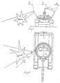
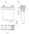
  1. A self-defence system of a carrier, for example a tank, comprising: a radar (2) to search for and measure trajectory parameters of an attacking munition, and rounds placed on upper parts of said carrier and forming an all-round defence, each round being located in a launch device (3) and having a propelling charge (5) and an antiprojectile (1), characterized in that said system is outfitted with: a prediction block of entry of the attacking munition to a system's kill envelope, a block for round selection and generation of ejection and detonation command, wherein the round is put into the launch pit (3) of a rectangular cross-section placed at an inclination preferably at an angle of 25° to 40° to a vertical axis of the carrier, the antiprojectile (1) includes a case (4) of a box-type shape made preferably of a non-metallic material, a fragmentation charge (9) in form of a plate, a fragmentation lining (8) to form a directed fragment field, and a fuze (10) is coupled via a communication line (6) to the block for round selection and generation of ejection and detonation command.
  2. A self-defence system of a carrier as set forth in claim 1, wherein a range meter of said radar (2) comprises a first master oscillator (108) connected to a modulating signal generator (107), a first output thereof is connected to a first input of a transmitter signal modulator (101), a second input thereof is connected to a power amplifier (102) with an input of the latter connected to a first output of a second master oscillator (103), an output of the transmitter signal modulator (101) is connected to a transmitting antenna A1, a second output of the modulating signal generator (107) is connected to an input of a delayed modulating signal generator (111), an output thereof is connected to a first input of a local oscillator signal modulator (105) with a second input of the latter connected to an output of a first frequency converter (104), a first input thereof is connected to a second output of the second master oscillator (103) and a second input is connected to an output of a third master oscillator (109), an output of the local oscillator signal modulator (105) is connected to a power divider (110) with the latter's first output connected to a first input of a second frequency converter (112) of a reference channel, a second input thereof is connected to a first receiving antenna (A2), a second output of the power divider (110) is connected to a first input of a third frequency converter (117) of a measurement channel, a second input thereof is connected to a second receiving antenna (A3), a second input of the delayed modulating signal generator (111) is connected to a memory block (106) of estimated detection zones of the attacking munition.
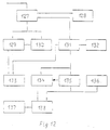
  3. A self-defence system of a carrier as set forth in claims 1,2, wherein said prediction block of entry of the attacking munition into the system's kill envelope comprises a meter (128) to measure a phase difference between signals of the reference and measurement channels, an output of the meter (128) is connected to a first input of a generalized coordinates determination device (127), a first output thereof is connected to a first input of a calculator (131) of flight time of the attacking munition to a calculated boundary of the kill envelope, a second output is connected to a storage register (130) of a preceding coordinate and to a first input of a comparison circuit (129), a second input thereof is connected to an output of the storage register (130) of the preceding coordinate, an output of the comparison circuit (129) is connected to a first input of a round number determination device (133) with the latter's second input connected to a first output of the calculator (131) of the flight time of the attacking munition to the calculated boundary of the kill envelope, a second input thereof is connected to a Doppler frequency meter (132), and its second output is connected to a first gate (135) and to an input of a first controlled time counter (134) of generation of a round ejection command, a second input of the first gate (135) is connected to an output of a fourth master oscillator (136), an output of the first gate (135) is connected to a second input of the first controlled time counter (134) of generation of the round ejection command, an output thereof is connected to a first input of a second gate (138) with the latter's second input connected to an output of the fourth master oscillator (136), and an output of the second gate (138) is connected to a second controlled time counter (137) of generation of an antiprojectile detonation command.
  4. A self-defence system of a carrier as set forth in claims 1,2,3, wherein said block for round selection and generation of ejection and detonation command comprises an analyzer (142) of a pulse train passage sequence, a first input thereof is connected to the round number determination device (133) and a second input to outputs of both the first time counter (134) of generation of the round ejection command and the second time counter (137) of generation of the antiprojectile detonation command, and an output thereof is connected to a timer (143) input with the latter's output connected to a third gate (145), and a fourth gate (144) coupled to reservoir capacitors (C1,C2) which are connected to anodes of first thyristors (V1,V2), the former of the two is controlled by a first shaper (141) of the round ejection pulse and the latter by a second shaper (140) of the antiprojectile detonation pulse, with cathodes of the first thyristors (V1,V2) connected to anodes of second thyristors (V11,V12,...V1n) and anodes of third thyristors (V21,V22,...V2n) controlled by a round number decoder (139), with an input thereof being connected to the round number determination device (133), cathodes of the second thyristors (V11,V12,...V1n) connected to igniters (B11,B12,.... B1n) of the propelling charges (5), cathodes of the third thyristors (V21,V22,...V2n) connected to deto nators (D21,D22,...D2n) to initiate the antiprojectile (1).
  5. A self-defence system of a carrier as set forth in claim 1, wherein said antiprojectile (1) is outfitted with a correction pulse engine (17) to turn it about its centre of mass and whith is coupled through a communication line to said block for round selection and generation of ejection and detonation command.
EP94903183A 1993-12-01 1993-12-01 Vehicle self-defence system Expired - Lifetime EP0687885B1 (en)

Applications Claiming Priority (1)

Application Number Priority Date Filing Date Title
PCT/RU1993/000289 WO1995015473A1 (en) 1993-12-01 1993-12-01 Vehicle self-defence system

Publications (3)

Publication Number Publication Date
EP0687885A1 EP0687885A1 (en) 1995-12-20
EP0687885A4 EP0687885A4 (en) 1996-12-20
EP0687885B1 true EP0687885B1 (en) 1998-09-16

Family

ID=20129817

Family Applications (1)

Application Number Title Priority Date Filing Date
EP94903183A Expired - Lifetime EP0687885B1 (en) 1993-12-01 1993-12-01 Vehicle self-defence system

Country Status (3)

Country Link
EP (1) EP0687885B1 (en)
DE (1) DE69321142T2 (en)
WO (1) WO1995015473A1 (en)

Cited By (2)

* Cited by examiner, † Cited by third party
Publication number Priority date Publication date Assignee Title
CZ303331B6 (en) * 2011-05-25 2012-08-01 Ceské vysoké ucení technické v Praze Fakulta elektrotechnická Microwave system for detecting, localizing and identifying endangering projectiles
DE102010016560C5 (en) * 2010-04-21 2014-06-05 Krauss-Maffei Wegmann Gmbh & Co. Kg Vehicle, in particular military combat vehicle

Families Citing this family (11)

* Cited by examiner, † Cited by third party
Publication number Priority date Publication date Assignee Title
DE19601756C1 (en) * 1996-01-19 2000-12-28 Diehl Stiftung & Co Method, for projecting armored object from projectiles, involves shooting grenade against projectile and igniting war head of grenade if shock wave of war head is behind center of mass f projectile
FR2851663B1 (en) * 2003-02-20 2006-03-03 Saint Louis Inst METHOD AND APPARATUS FOR DETERMINING A QUICK MOBILE TRACK BY MEASURING THE APPARENT SPEED AND KALMAN FILTERING
FR2851816B1 (en) * 2003-02-28 2006-06-16 METHOD FOR DEFENSE OF A VEHICLE OR A STRUCTURE AGAINST A THREAT AND DEFENSE DEVICE USING THE SAME
DE602004017072D1 (en) * 2003-02-28 2008-11-27 Nexter Munitions A method of defending a car or facility against a threat such as a bullet and apparatus for carrying out this method
DE102005038071A1 (en) * 2005-08-10 2007-02-15 Rheinmetall Waffe Munition Gmbh Device and method for protecting vehicles from ammunition, especially in front of shaped charge projectiles
FR2909441B1 (en) 2006-12-04 2009-02-20 Nexter Munitions Sa DEVICE FOR DEFENSE OF A PLATFORM AGAINST A THREAT
US8701538B2 (en) 2007-03-29 2014-04-22 Mechanical Solutions, Inc. System for protection against missiles
US20090173250A1 (en) * 2007-03-29 2009-07-09 Mechanical Solutions Inc. System for protection against missiles
DE102010025801A1 (en) * 2010-07-01 2012-01-05 Diehl Bgt Defence Gmbh & Co. Kg Active defense system for light combat vehicles
JP6296122B2 (en) * 2016-08-31 2018-03-20 ダイキン工業株式会社 Interception system
DE102019133786A1 (en) 2019-12-10 2021-06-10 Krauss-Maffei Wegmann Gmbh & Co. Kg Movable protection device for military vehicles with distance-active protection system

Family Cites Families (8)

* Cited by examiner, † Cited by third party
Publication number Priority date Publication date Assignee Title
DE1903951A1 (en) * 1969-01-28 1977-01-27 Porsche Ag Shell interceptor and exploder for armoured vehicle - has spray cleaned optical detector triggering sensor pulses
DE2031883C3 (en) * 1970-06-27 1975-06-26 Messerschmitt-Boelkow-Blohm Gmbh, 8000 Muenchen System for defense against aircraft or missiles approaching a target object
DE3410467A1 (en) * 1984-03-22 1985-09-26 Rheinmetall GmbH, 4000 Düsseldorf Multi-barrel weapon system
IL74961A0 (en) * 1985-04-17 1985-08-30 Spectronix Ltd Apparatus for the detection and destruction of incoming objects
DE3608108C1 (en) * 1986-03-12 1990-06-07 Diehl Gmbh & Co Defense against flying objects
DE3733962A1 (en) * 1987-10-08 1989-04-27 Wegmann & Co METHOD FOR AUTOMATIC TARGET CLASSIFICATION BY AGRICULTURAL AND WATER COMBATING VEHICLES AND DEVICE FOR CARRYING OUT SAID METHOD
DE4125355C1 (en) * 1991-07-31 1993-01-28 Buck Werke Gmbh & Co, 7347 Bad Ueberkingen, De
US5229540A (en) * 1992-05-26 1993-07-20 The United States Of America As Represented By The Secretary Of The Army Tank alerting system

Cited By (2)

* Cited by examiner, † Cited by third party
Publication number Priority date Publication date Assignee Title
DE102010016560C5 (en) * 2010-04-21 2014-06-05 Krauss-Maffei Wegmann Gmbh & Co. Kg Vehicle, in particular military combat vehicle
CZ303331B6 (en) * 2011-05-25 2012-08-01 Ceské vysoké ucení technické v Praze Fakulta elektrotechnická Microwave system for detecting, localizing and identifying endangering projectiles

Also Published As

Publication number Publication date
DE69321142T2 (en) 1999-02-25
EP0687885A4 (en) 1996-12-20
DE69321142D1 (en) 1998-10-22
EP0687885A1 (en) 1995-12-20
WO1995015473A1 (en) 1995-06-08

Similar Documents

Publication Publication Date Title
EP0687885B1 (en) Vehicle self-defence system
US4160415A (en) Target activated projectile
US7202809B1 (en) Fast acting active protection system
US4176814A (en) Terminally corrected projectile
US7104496B2 (en) Active protection device and associated apparatus, system, and method
US6513438B1 (en) Method for offering a phantom target, and decoy
US8464949B2 (en) Method and system for countering an incoming threat
US7066427B2 (en) Active protection device and associated apparatus, system, and method
US4215630A (en) Anti-ship torpedo defense missile
US20080291075A1 (en) Vehicle-network defensive aids suite
EP0138942B1 (en) Means for reducing spread of shots in a weapon system
US6044765A (en) Method for increasing the probability of impact when combating airborne targets, and a weapon designed in accordance with this method
WO2005003676A2 (en) Method and system for destroying rockets
US5841059A (en) Projectile with an explosive load triggered by a target-sighting device
US3758052A (en) System for accurately increasing the range of gun projectiles
RU2102678C1 (en) Vehicle self-defense system
US5147973A (en) Multi-option fuze system
Nasser et al. Recent advancements in proximity fuzes technology
US20090007766A1 (en) Cruise munitions detonator projectile
RU2601241C2 (en) Ac active protection method and system for its implementation (versions)
RU95122733A (en) VEHICLE SELF-DEFENSE SYSTEM
EP2942597B1 (en) An active protection system
RU2336486C2 (en) Complex of aircraft self-defense against ground-to-air missiles
GB2410786A (en) Method and apparatus for the protection of battlefield vehicles
US6318273B1 (en) Shaped-charge projectile and weapon system for launching such a projectile

Legal Events

Date Code Title Description
PUAI Public reference made under article 153(3) epc to a published international application that has entered the european phase

Free format text: ORIGINAL CODE: 0009012

AK Designated contracting states

Kind code of ref document: A1

Designated state(s): BE CH DE FR GB IT LI NL SE

17P Request for examination filed

Effective date: 19950727

A4 Supplementary search report drawn up and despatched
AK Designated contracting states

Kind code of ref document: A4

Designated state(s): BE CH DE FR GB IT LI NL SE

17Q First examination report despatched

Effective date: 19970403

GRAG Despatch of communication of intention to grant

Free format text: ORIGINAL CODE: EPIDOS AGRA

GRAG Despatch of communication of intention to grant

Free format text: ORIGINAL CODE: EPIDOS AGRA

GRAH Despatch of communication of intention to grant a patent

Free format text: ORIGINAL CODE: EPIDOS IGRA

GRAH Despatch of communication of intention to grant a patent

Free format text: ORIGINAL CODE: EPIDOS IGRA

GRAA (expected) grant

Free format text: ORIGINAL CODE: 0009210

AK Designated contracting states

Kind code of ref document: B1

Designated state(s): BE CH DE FR GB IT LI NL SE

PG25 Lapsed in a contracting state [announced via postgrant information from national office to epo]

Ref country code: NL

Free format text: LAPSE BECAUSE OF FAILURE TO SUBMIT A TRANSLATION OF THE DESCRIPTION OR TO PAY THE FEE WITHIN THE PRESCRIBED TIME-LIMIT

Effective date: 19980916

Ref country code: IT

Free format text: LAPSE BECAUSE OF FAILURE TO SUBMIT A TRANSLATION OF THE DESCRIPTION OR TO PAY THE FEE WITHIN THE PRE;WARNING: LAPSES OF ITALIAN PATENTS WITH EFFECTIVE DATE BEFORE 2007 MAY HAVE OCCURRED AT ANY TIME BEFORE 2007. THE CORRECT EFFECTIVE DATE MAY BE DIFFERENT FROM THE ONE RECORDED.SCRIBED TIME-LIMIT

Effective date: 19980916

Ref country code: BE

Free format text: LAPSE BECAUSE OF FAILURE TO SUBMIT A TRANSLATION OF THE DESCRIPTION OR TO PAY THE FEE WITHIN THE PRESCRIBED TIME-LIMIT

Effective date: 19980916

REG Reference to a national code

Ref country code: CH

Ref legal event code: NV

Representative=s name: A. BRAUN, BRAUN, HERITIER, ESCHMANN AG PATENTANWAE

Ref country code: CH

Ref legal event code: EP

REF Corresponds to:

Ref document number: 69321142

Country of ref document: DE

Date of ref document: 19981022

PGFP Annual fee paid to national office [announced via postgrant information from national office to epo]

Ref country code: SE

Payment date: 19990104

Year of fee payment: 6

ET Fr: translation filed
PGFP Annual fee paid to national office [announced via postgrant information from national office to epo]

Ref country code: CH

Payment date: 19990125

Year of fee payment: 6

NLV1 Nl: lapsed or annulled due to failure to fulfill the requirements of art. 29p and 29m of the patents act
PLBE No opposition filed within time limit

Free format text: ORIGINAL CODE: 0009261

STAA Information on the status of an ep patent application or granted ep patent

Free format text: STATUS: NO OPPOSITION FILED WITHIN TIME LIMIT

26N No opposition filed
PG25 Lapsed in a contracting state [announced via postgrant information from national office to epo]

Ref country code: SE

Free format text: LAPSE BECAUSE OF NON-PAYMENT OF DUE FEES

Effective date: 19991202

PG25 Lapsed in a contracting state [announced via postgrant information from national office to epo]

Ref country code: LI

Free format text: LAPSE BECAUSE OF NON-PAYMENT OF DUE FEES

Effective date: 19991231

Ref country code: CH

Free format text: LAPSE BECAUSE OF NON-PAYMENT OF DUE FEES

Effective date: 19991231

EUG Se: european patent has lapsed

Ref document number: 94903183.5

PGFP Annual fee paid to national office [announced via postgrant information from national office to epo]

Ref country code: GB

Payment date: 20011206

Year of fee payment: 9

REG Reference to a national code

Ref country code: GB

Ref legal event code: IF02

PG25 Lapsed in a contracting state [announced via postgrant information from national office to epo]

Ref country code: GB

Free format text: LAPSE BECAUSE OF NON-PAYMENT OF DUE FEES

Effective date: 20021201

GBPC Gb: european patent ceased through non-payment of renewal fee
PGFP Annual fee paid to national office [announced via postgrant information from national office to epo]

Ref country code: FR

Payment date: 20040630

Year of fee payment: 11

Ref country code: DE

Payment date: 20040630

Year of fee payment: 11

PG25 Lapsed in a contracting state [announced via postgrant information from national office to epo]

Ref country code: DE

Free format text: LAPSE BECAUSE OF NON-PAYMENT OF DUE FEES

Effective date: 20050701

PG25 Lapsed in a contracting state [announced via postgrant information from national office to epo]

Ref country code: FR

Free format text: LAPSE BECAUSE OF NON-PAYMENT OF DUE FEES

Effective date: 20050831

REG Reference to a national code

Ref country code: FR

Ref legal event code: ST