EP0685973B1 - Allocation de portes radio dans un système de communication cellulaire mobile - Google Patents
Allocation de portes radio dans un système de communication cellulaire mobile Download PDFInfo
- Publication number
- EP0685973B1 EP0685973B1 EP95303489A EP95303489A EP0685973B1 EP 0685973 B1 EP0685973 B1 EP 0685973B1 EP 95303489 A EP95303489 A EP 95303489A EP 95303489 A EP95303489 A EP 95303489A EP 0685973 B1 EP0685973 B1 EP 0685973B1
- Authority
- EP
- European Patent Office
- Prior art keywords
- radio
- ports
- port
- group server
- radio port
- Prior art date
- Legal status (The legal status is an assumption and is not a legal conclusion. Google has not performed a legal analysis and makes no representation as to the accuracy of the status listed.)
- Expired - Lifetime
Links
Images


Classifications
-
- H—ELECTRICITY
- H04—ELECTRIC COMMUNICATION TECHNIQUE
- H04W—WIRELESS COMMUNICATION NETWORKS
- H04W88/00—Devices specially adapted for wireless communication networks, e.g. terminals, base stations or access point devices
-
- H—ELECTRICITY
- H04—ELECTRIC COMMUNICATION TECHNIQUE
- H04W—WIRELESS COMMUNICATION NETWORKS
- H04W88/00—Devices specially adapted for wireless communication networks, e.g. terminals, base stations or access point devices
- H04W88/08—Access point devices
- H04W88/085—Access point devices with remote components
-
- H—ELECTRICITY
- H04—ELECTRIC COMMUNICATION TECHNIQUE
- H04W—WIRELESS COMMUNICATION NETWORKS
- H04W84/00—Network topologies
- H04W84/02—Hierarchically pre-organised networks, e.g. paging networks, cellular networks, WLAN [Wireless Local Area Network] or WLL [Wireless Local Loop]
- H04W84/04—Large scale networks; Deep hierarchical networks
- H04W84/042—Public Land Mobile systems, e.g. cellular systems
Definitions
- the invention relates to radio communication systems and, more particularly, to an arrangement for providing a radio communication system access to a switching network.
- the telecommunications service vision for the future includes personal communications services (PCS), a term which denotes ubiquitous service for voice, data and other digital services from/to any place.
- PCS personal communications services
- the PCS service definition also includes radio ports for providing ubiquitous wireless access to the switched network from small, light-weight, low-power PCS radio terminals (portables or mobiles).
- Another future telecommunications network might be a wireless subscriber loop, in which the link between customers and the network is a fixed or nearly fixed radio link rather than copper twisted-pair. We illustrate our invention in the context of PCS but it is fully applicable to other radio access networks such as wireless subscriber loop.
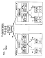
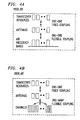
- Each geographical area called a microcell (M1 - MM), includes a radio port (RP1 - RPM) used to transmit and receive multiplexed radio frequency (RF) signals to/from multiple mobiles (101-110, 111-120).
- RP1 - RPM radio port
- RF radio frequency
- Each mobile has a separate channel in the multiplexed RF signal (e.g., 101 uses RF1).
- the different radio frequency (RF) channels served by a radio port are defined in time (i.e., TDMA), frequency (i.e., FDMA), or code space (i.e., CDMA), or some combination thereof.
- Each RF signal channel received by the radio port is processed by a multi-channel receiver module (e.g., MCR1) which produces a received digital signal stream from each channel (e.g., DIR from RFIR).
- MCR1 multi-channel receiver module
- the transmitted signals require a multi-channel transmitter module (e.g., MCT1) at the radio port.
- the radio ports are connected via dedicated baseband digital lines (130) to a local radio access controller (140) which provides access to the switching network (160) via dedicated baseband digital lines (150).
- microcell In a PCS network, there are expected to be numerous radio ports, each using low power and radiating in a limited geographical area called a microcell. Smaller cells allow more frequency re-use within a geographical area, thus resulting in a larger capacity (maximum number of calls for given radio spectrum) in that area. With smaller cells, the RF transmission power can be lower.
- a microcell is expected to have a radius from 150 to 300 meters. For many scenarios, e.g., residential suburbs, the microcell size choice is driven more by low-power (10 to 100 mW) requirements than capacity requirements. The small cell size results in a very large number of microcells, each with a radio port, needed to cover a given geographical area.
- FIG. 1B shows another illustrative prior art proposed PCS network with analog RF transport and fixed simulcasting (for example, see Cablevision Systems Corporation's FCC Experimental License Progress Reports , November 1992 and August 1993).
- Radio access within a microcell is provided by a platform microcell repeater (RI - RM).
- the multi-channel transmitter (MCT1) and receiver (MCRl) in FIGS. 1A and 1B are similar and operate in the same manner. In FIG. 1B, they are shared by the microcells MI - MM and located remotely from them in base station 180.
- the radio users in FIGS. I A and 1B (101-110, 111-120) are identical and operate in the same manner.
- the air interface signals are transported in analog form between the repeaters R1 - RM and the base station over coaxial cable network 170.
- the downstream signals and upstream signals undergo block frequency conversion in the transmit block frequency converters (TFC1 - TFCM) and the receive frequency converters (RFC1 - RFCM), respectively.
- the base station 180 provides access to the switching network 160 using digital lines 150. Capacity is shared among a group of microcells by radiating the same air-frequency signal from the repeaters of the microcells in the group. In the upstream direction, the information received by each repeater is combined with that of other repeaters in the group. We call this mode of operation single-frequency simulcasting.
- Prior art microcellular systems that use analog RF transport like the one shown in FIG. 1B, use fixed simulcasting in which the composition of the simulcast group of microcells is predetermined and fixed. Since the microcells of a simulcast group also define a radio coverage area over which capacity is shared, there are fixed simulcast areas in which capacity is shared.
- the prior art includes the concept of cell-splitting in which a simulcast group is split into two simulcast groups in order to accommodate a growth in traffic.
- the prior art systems are limited, however, in that they cannot respond to dynamic variations in the spatial distribution of traffic.
- the radio port in the prior art has some of the technology needed for effecting a reconfiguration of the simulcast group, the prior art systems do not include a control architecture that supports dynamic reconfiguration. Moreover, superimposing a control architecture on the system shown in FIG. 1B is not sufficient.
- EP-A-0 368 673 discloses a communications system having a base centre with radio transceivers for providing a number of RF communications links and a plurality of fixed radio ports through which RF signals can be transmitted and received over the air.
- a fibre optic network interconnects the RF transceivers and the fixed radio ports, and carries the RF signals by means of optical signals.
- a matrix switch selectively interconnects the transceivers and the radio ports through the fibre optic network.
- the microcellular system includes a local radio access controller which dynamically controls the assignment of a radio port to one of a plurality of sets, each served by a radio port group server. Radio ports in one set are operated in single-frequency or multi-frequency simulcast mode. Multi-frequency simulcast refers to operation in which the information transmitted from multiple radio ports is the same, but the air-frequency bands are different.
- the radio ports in one set share the capacity of a radio port group server, and all the capacity of the radio port group server can be made available to one radio port. More particularly, the present invention enables radio ports assigned to a first set to be reassigned by the server to a second radio port set in response to a predetermined condition.
- One illustrative condition is when the number of active users in the first set approaches the maximum user capacity of the first set.
- the system can be used for FDMA, TDMA, and CDMA types of radio transmissions over the air.
- the transport medium connecting the radio ports can be coaxial cable, optical cable, or a radio type facility.
- radio port identification information is communicated from the radio ports to the group server by a signal either superimposed on the data signals or carried on a separate channel, thus allowing the group server to map the dynamic distribution of users.
- the mobile units of FIG. 1A (e.g., 101-110) and of FIG. 2A (e.g., 270-279) are identical and operate in the same manner.
- Each mobile unit (e.g., 101) may receive voice or data which is digitized, illustratively, into a digital channel (e.g., D1) and then modulated onto one of the RF frequencies (RF1 - RFN) available at radio port RP1.
- RF1 - RFN RF frequencies
- mobile unit 101 was assigned RF frequency RF1, although it could have been assigned to any unoccupied radio frequency in the frequency band RF1 - RFN handled by radio port RP1.
- the multi-channel receiver module MCR1 of RP1 receives the modulated signal RFIR transmitted from mobile unit 101 and converts it into the received digital signal DIR. Similarly, the transmitted digital signal DIT is modulated by multi-channel transmitter MCT1 to produce a modulated signal RFIT (RF1T ⁇ RFIR) transmitted from RP1 and received by mobile unit 101. Controller I of RP1 controls the selection of radio frequencies RF1- RFN and the modulation/demodulation of the digital signal/RF signal, respectively. Controller 1 also controls the transmitting/receiving of the digital signals to/from the Local Radio Access Controller (LRAC) 140 over one of the communication facilities 130. In radio port RPM, controller M and multi-channel module MCRM and multi-channel transmitter module MCTM perform the same functions for mobile units 111-120.
- LRAC Local Radio Access Controller
- FIG. 2A is described as utilizing well-known Frequency-Division Multiple Access (FDMA) over the common-air interface, other well-known modulation schemes such as Time Division Multiple Access (TDMA) or Code Division Multiple Access (CDMA) could also be utilized.
- FDMA Frequency-Division Multiple Access
- TDMA Time Division Multiple Access
- CDMA Code Division Multiple Access
- the function of the radio port RP1 is that of a receiving/transmitting antenna and frequency converter. This is implemented with very low-cost RF components.
- the components used here are close to the bare minimum for any radio port attached to a broadband coax medium. Any analog transport scheme using broadband coax would typically use frequency conversion to enable transport at frequencies compatible with the coaxial cable transmission characteristics, as well as the frequency spectrum of other services which share the cable (e.g., cable television (CATV) distribution).
- CATV cable television
- the use of programmable oscillators (PO) rather than fixed ones provides an improvement of the present invention over the prior art illustratively shown in FIG. 1B.
- the programmable oscillator allows the radio port to dynamically access any of the radio port group servers which are on the same network. For example, each radio port group server would be assigned its own frequency band for communicating to its simulcast set of radio ports over the shared broadband network. By simply retuning the programmable oscillator in the radio port, the radio port could be reassigned from the simulcast sets of a first radio port group server to that of a second radio port group server.
- the simulcast groups of radio ports access their respective radio port group servers using dynamic frequency-division multiple access (FDMA). This functionality is achieved at nominal increase in cost and complexity and will be discussed more completely in the description of FIG. 3.
- FDMA dynamic frequency-division multiple access
- Another feature of the present invention is the centralized location and sharing of hardware resources.
- the radio ports do not include digital transceiver resources. Instead, these transceiver resources are located centrally at the server 200 location. Further, the dynamic FDMA feature of the present invention allows optimal sharing of the transceiver resources. Since the radio ports share resources at a central location and do not have dedicated resources, two important cell-planning issues of adequate radio coverage and adequate capacity (spectrum and transceiver resources) are decoupled. Radio ports (microcells) can be installed to provide adequate radio coverage, while the capacity demands of a geographic region are met by the aggregate capacity of all the multi-channel transceivers at the hub.
- a transceiver which serves 10 microcells would have to have 30 frequency channels to provide the same blocking, probability, a 56% reduction from the dedicated case. These 30 channels would be shared by the mobile units served by all the radio ports, RP1- RPM, served by server 200 of FIG. 2A.
- each of the radio ports RP1...RPM can utilize up to 30 channels so long as the total of the channels utilized by radio ports RP1...RPM (served by server 200) does not exceed 30 channels.
- Utilization of the PCS network of the present invention results in either 1) a reduced probability of blocking for a given number of mobile units or 2) a greater number of mobile units being accommodated with the same probability of blocking than is possible in the proposed prior art PCS network of FIG. 1A.
- an improvement provided by the present invention is the ability to dynamically allocate hardware resources and spectrum.
- the FIG. 2A arrangement is designed to enable this grouping in a flexible manner.
- a straightforward means of grouping a set of microcells together is to radiate the same information from the radio ports of the microcells in the group. Similarly, during a receive operation, all the information at all the radio ports in the set is combined as one. This mode of operation is called simulcast.
- the radio ports which operate in simulcast mode are fixed in a predetermined manner such that it is difficult to change the composition of radio ports in the simulcast groups; we term this fixed simulcast.
- the present invention provides for multiple radio port group servers to share the same broadband medium using FDMA. By exploiting the functionality of the programmable oscillators and filters in the radio port, each radio port can be assigned to select the signal from any one of the radio port group servers.
- the set of radio ports which communicate with one radio port group server and form a simulcast group can be modified in an arbitrary and dynamic manner.
- This capability further increases the efficiency of transceiver use because the effective number of users sharing the resources is larger than in the fixed simulcast case. Thus even fewer transceiver channels are required to provide a particular blocking probability.
- this operation dynamic simulcast.
- a system involving simulcast typically involves a handoff when the mobile moves from one simulcast group server to another, but not when a mobile moves within a simulcast group.
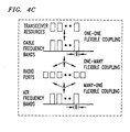
- each antenna has a one-to-one relationship with the air frequency bands (each air frequency band may include one or more channels).
- DCA Dynamic Channel Allocation
- the hardware resources are shared within one cell while the air spectrum is shared across multiple cells as shown in FIG. 4B. In other words, the air channels that can be used at one antenna are not fixed to one band, but are dynamically allocated.
- the hardware resources are dedicated to each cell. Under non-uniform traffic distribution across cells, even though the spectral resources are used efficiently through dynamic channel allocation, the hardware resources at each cell must be budgeted for some maximum traffic. This could be wasteful, especially as the size of (micro)cells shrinks.
- the present invention shares both spectrum and hardware resources.
- the assignment of radio ports to cable bands (with each cable band serving one simulcast group) is flexible. So is the choice of the air bands used at each of the radio ports.
- Dynamic allocation is achieved by dedicating hardware resources and spectrum to each resource-sharing group server, and allowing the assignment of microcells to group servers to be dynamic and flexible. Capacity allocation thus involves channel allocation as well as hardware resource allocation.
- a hotspot is a highly localized group of radio users which can potentially overload a microcell. For example, mobile units located in automobiles stuck in a traffic jam overload the local microcells while other microcells along the highway remain less utilized. In a system with immobile users, such as wireless subscriber loop, a hotspot can occur when one or more users in one microcell take up a lot of bandwidth. Dynamic allocation enables the server to reassign a radio port from a busy simulcast group to another less busy simulcast group, thereby enabling the remaining radio ports of the busy simulcast group to increase their average traffic per cell. In the most extreme case, a single radio port can take all the resources of the multi-channel transceiver, the simulcast group therefore consisting of exactly one radio port.
- multi-channel transmitter/receiver (transceiver) module e.g., MCR1 and MCT1 typically found in an RP1, as shown in FIG. 1A
- MCR1 and MCT1 typically found in an RP1, as shown in FIG. 1A
- multi-channel transceiver 201 resources are shared among all mobile units of all of the microcells (RP1, RP2, ... RPM) rather than having each microcell transceiver shared only among the mobile units of that cell.
- each radio port RPI - RPM does not demodulate the RF signal to a digital signal stream as in FIG. 1, but rather functions as a frequency converter to convert the modulated RF signal to a frequency band compatible with the coaxial cable, optical fiber, or microwave radio distribution network, hereinafter network 230, used to distribute the RF signals between server 200 and radio ports RP1 - RPM.
- the network 230 can utilize a tree-and-branch or other topology.
- the signals carried between the server 200 and the radio ports RP1 - RPM are multiplexed, modulated RF analog signals (analog transport).
- the frequency conversion of the RF frequencies in the radio ports RP1- RPM ensure that low-loss and spectrum-compatible transmission occurs over the network 230.
- the RF components utilized in radio port RP1 250, of FIG. 2A are essentially the same low-cost RF components that would have been utilized in the RF front end of the radio ports of FIG. 1.
- the programmable oscillators (PO) 253 and 262 replace the fixed oscillator of the radio ports of FIG. 1.
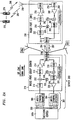
- the PCS network of FIG. 2A includes a server 200 including radio port group server 210 and multi-channel transceiver 201 which connects over dedicated baseband digital lines 202 to switching center 202A.
- the server 200 connects over network 230 to radio ports RP1 (250), RP2 through RPM.
- Controller 221 of server 200 sends/receives control signals over a control signaling channel of network 230 to controller 264 of radio port 250.
- the control signal enables controller 221 of radio port group server 210 to control the frequency of programmable oscillator 253 and 262 of radio port 250.
- the multi-channel transceiver 201 of server 200 includes the transceiver utilized by radio ports RP1 - RPM.
- Radio port group server 210 includes narrowband filter 211 which couples the multiple bands of analog frequency signals from the multi-channel transmitter 203 of transceiver 201 to mixer 212.
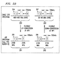
- mixer 212 the multiple frequency bands from filter 211 are mixed with the frequency from programmable oscillator PO 222 into the cable spectrum frequency bands shown by 290 of FIG. 2B.
- the bandpass filter 213 couples the signals from mixer 212 to amplifier 214 which amplifies the signal before it is coupled through directional coupler 215 to network 230.
- radio port 250 is handling the downlink frequency band (shown as 294 of FIGS. 2A and 2B) that extends from 480.0 - 480.7 MHz.
- the frequency band signal at 480.0 - 480.7 MHz passes through splitter/coupler 251 to bandpass filter 252.
- the filtered output signal then is up-converted or modulated in mixer 254 with a 1700 MHz signal from PO 253 to generate a 2180.0 - 2180.7 MHz signal (shown as frequency band 295 of FIGS. 2A and 2B).
- the 2180.0 - 2180.7 MHz signal is filtered by narrowband filter 255, amplified by amplifier 256 and coupled via directional coupler 257 to antenna 258 of radio port 250.
- the 2180.0 - 2180.7 MHz signal is then transmitted to the active mobile units 270 - 279.
- the corresponding 2130.0 - 2130.7 MHz uplink signal (shown as frequency band 296 of FIGS. 2A and 2B) is received from the active mobile units (270 - 279) by antenna 258 and coupled by directional coupler 257 to narrowband filter 259.
- the uplink signal output of narrowband filter 259 is amplified by amplifier 260 and down-converted or demodulated in mixer 261 using a 2100 MHz signal from PO 262 to obtain a 30.0 -30.7 MHz signal representing the uplink frequency band (shown as 297 of FIGS. 2A and 2B).
- the output of mixer 261 is filtered by 263 and coupled by directional coupler 251 to network 230.
- the 30.0 - 30.7 MHz uplink frequency band signal 297 is coupled by directional coupler 215 to filter 216.
- the output of filter 216 is demodulated in mixer 217 using the signal from PO 218, filtered by filter 219 and amplified by amplifier 220.
- the signal output of amplifier 220 is converted to a digital signal in the multi-channel receiver 204 of transceiver 201 and sent over digital lines 202 to switching network 202A.
- radio port server 210 handles the frequency band 1 (comprising the frequency band 480.0 - 480.7 MHz).
- the frequency band I can be accessed by any of the radio ports RP1 - RPM which connect to network 230.
- control unit 221 can dynamically assign 10 communication channels among the users in microcells M1 - MM served by the radio ports RP1 - RPM.
- each of the radio ports RP1 - RPM can serve up to 10 active users so long as the total number of active users served by radio ports RP1 - RPM does not exceed 10 active users
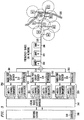
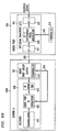
- a server 350 (including multiple radio pon group servers 301, 302 and 303) can share, via coupler 314. the distribution network 320 and radio ports A 1 - A 4, B 1 - B 3, and C 1 - C 2.
- group servers 301, 302 and 303, transceiver hardware resources 307, 308 and 309, and radio ports A 1 - A 4, B 1 - B 3 and C 1 - C 2 operate in the same manner as previously described in FIG. 2.
- Server 350 connects, via local radio access controller 340, to switching center 300.
- Each simulcast group server 301 - 303 is mapped to its own cable frequency band 304 - 306, respectively, and allocated a set of transceiver hardware resources 307 - 309, respectively.
- each group server all the users in the microcells belonging to the group share the network band and hardware resources.
- a user in a microcell served by radio port A 1 can use a frequency channel 311 and maintain that channel when he/she moves to another microcell in the same simulcast group, such as the microcell served by radio port A 2.
- the network channel will be determined by a time slot and a user code, respectively.
- users served by radio port A 1 can "hog" all the channels of frequency band A 304 allocated to server A 301, leaving no channels for users in the microcells served by radio ports A 2, A 3 and A 4.
- the total frequency channel allocation to server A 301 can be arbitrarily shared among the radio ports A 1, A 2, A 3 and A 4. This is the same as fixed simulcast.
- the assignment of radio ports can be changed from one group server to another in response to predetermined conditions.
- group server B 302 and its associated radio ports B1- B 3 are located to serve a highway 330.
- the group server B 302 has transceiver hardware 308 sufficient to handle M channels (or users).
- up to M channels can be utilized by any of the radio ports B 1 - B 3 so long as the total used by all of the radio ports B 1 - B 3 do not exceed the M channels allocated to group server B 302.
- the controller 318 of group server B 302 includes means for detecting when the number of active users equals a predetermined number M1 which is less than or equal to its user capacity M. When this occurs, the controller 318 of group server B 302 communicates over path 312 to the controller 317 of group server A 301 to arrange the reassigning of radio port B 3 to server group A 301.
- group server A 301 If group server A 301 is operating at an active user load of N1, well below its maximum user capacity of N, then it may be willing to accept that assignment of radio port B 3 as long as the resulting user load N2 is still less than N. The result is that radio port B 3 would be reassigned as radio port A 5 as part of group server A 301. Group server B 302 would then be able to distribute its total user capacity M among only radio ports B 1 and B 2. The result is that each radio port B 1 and/or B 2 could now accept additional users.
- group server B 302 If user traffic further increased, it might be possible for group server B 302 to reassign radio port B 1 or B 2 to group server A 301 or to another group server, C 303, if excess capacity were available thereat. Rather than having controller 318 of group server B 302 checking with both the controllers 317 and 319 of group server A 301 and group server C 303, respectively, it may be more practical to have local radio access controller 340 monitor user traffic at group servers A - C and do the reassignment control function.
- the dynamic simulcast feature enables any radio port to access any multi-channel transceiver 307-309 of server 350.
- FIG. 6A illustrates a system control architecture of the present invention.
- the local radio access controller 340 is shown along with controller 310 of switching center 300, server A 350A, and a radio port 250.
- the control paths e.g., bus or channel 602, 604, 606) are shown as fine lines, and data paths (e.g., bus or channel 603, 605, 605A) are shown as bold lines.
- the controller intelligence can be distributed over one or more of the controller subsystems 310, 317, 340 and 610, or centralized at the radio access controller.
- the different controller subsystems 310, 317 and 340 communicate over a control channel.
- a digital control bus 602 provides control interfaces between the local radio access controller 340, the switch controller 310, and the radio port group server controller 317.
- a passband control channel 606 is provided between the radio port group server and the radio ports.
- the passband control channel 606 could be common for all of the radio ports in one group by using a common frequency carrier on the communications medium. It is also possible to have a dedicated control channel for each radio port. According to another aspect of the invention, the control information could be superimposed on the upstream air interface signals transported from the radio port to the radio port group server. Note that it is possible to implement the control architecture of the dynamic simulcasting system without altering the air interface protocol.
- the control channel 606 is used primarily to enable the dynamic monitoring of system condition and to perform dynamic configuration by changing assignment of the radio port from one cable band (and radio port group server) to another.
- a control bus 613 provides interfaces between the downstream transport section 612, upstream transport section 611 and controller 610.
- the controller 610 has direct access to the received upstream air interface signal. A possible use for this is to provide a radio port control function whereby the controller 610 monitors the received RF power. If the RF power is below a predetermined level as would occur when there are no active users in that microcell, the controller 610 could switch the radio port to standby by switching off the upstream amplifier (e.g., 260 of FIG. 2A). This would reduce the thermal noise delivered to the radio port group server A 301.
- Radio Port Identification and User Mapping Another radio port control function can be to support the Radio Port Identification and User Mapping (RPIUM) procedure, which we describe here.
- the controller 610 and the upstream signal transport section 611 of the radio port jointly send information back to the local radio access controller 340 to identify the particular radio port being used by each user.
- RPIUM procedures can be implemented with superimposed phase, frequency, or amplitude modulation.
- FIG. 6B illustratively shows an RPIUM procedure using superimposed phase information.
- the upstream transport section 611 of FIG. 6A is divided into sections UT-1 (625) and UT-3 (627).
- Radio port ID information is transmitted on a control channel 628 from the controller 610 and superimposed as phase information in a UT-2 stage 626.
- the signal with superimposed radio identification is transported upstream over the network 320.
- the radio port group server 301 that serves the simulcast group to which the radio port 250 belongs selects and block-translates the frequency band of the simulcast group.
- the receiver 620 selects the user channel through RF front end 623.
- the radio port ID information is extracted in the radio port ID extraction stage 622 and sent to the controller 317 over bus 624. This information can be shared with the various controllers shown in FIG. 6A in order to maintain a map of user distribution across the network.
- the user distribution information could be obtained by means other than the RPIUM procedure described above. For instance, information about the number of users being served by one radio port 250 could be estimated by the total received RF power at that port.
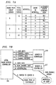
- the radio port group servers A, B, and C in FIG. 3 serve radio ports A1 - A4, B1- B3, and C1- C2, respectively. Let each radio port group server have a capacity of 20 radio users. From the RPIUM procedure, the local radio access controller 340 has a map of the user distribution. An illustrative distribution of users in shown in FIG. 7A. There are 16 users served by server A, 6 users served by server B, and 10 users by server C. The radio access controller 340 detects that there is an imbalance in user load across the three radio port group servers and that server A is at 80 percent of its capacity.
- the local radio access controller 340 determines that about 5 users should be transferred from server A to server B. Since microcells A3 and A4 each have 4 users, they are good candidates for transfer to server B. From the radio port map as shown in FIG. 3, it is apparent that microcell A3 adjoins the simulcast zone of server B whereas microcell A4 does not. The local radio access controller 340 thus selects A3 for transfer.
- the above is only an illustrative reconfiguration algorithm. Other algorithms could be used to address criteria such as load balance, cell contiguity, algorithm stability, fairness, mobility tracking, etc. Also, if user map information is not available, an algorithm which blindly transfers microcells one at a time until the load is balanced could be used.
- FIG. 7B shows an illustrative control flowchart for implementing dynamic reconfiguration for the transfer of radio port A3 to server B as described above. It is assumed that the RPIUM procedure includes the following steps in its operation:
- the radio port group server 500 includes the elements 211 - 214 and 216 - 222 of radio port group server 210 of FIG. 2A.
- the output of amplifier 214 is coupled via capacitor 501 to modulate optical transmitter (e.g., laser) 502.
- the modulated output of laser 502 passes over fiber 503 and directional coupler (combiner/splitter) 504 to fiber optic distribution network 505.
- the radio ports RP1 - RPM connect to the fiber optic network 505 via one or more couplers 506.
- Radio port RP1 510 includes the elements 252 - 264 of radio port 250 of FIG. 2A.
- the modulated optical signal passes through directional coupler 511 to optical detector 512 which converts the optical signal to an RF signal and couples the signal to filter 252. It is then processed as in FIG. 2A.
- the mobile unit RF signals received by antenna 258 are filtered, amplified, frequency-translated (by 259 - 261), and coupled by filter 263 to RF amplifier 515.
- the output of amplifier 515 is coupled via capacitor 516 to modulate optical transmitter (e.g., laser) 517.
- the optical signal passes over optical fiber 518 and directional coupler 511 to fiber optic network 505.
- radio port group server 500 the modulated optical signal passes through directional coupler 504 and is converted to an RF signal by optical detector 519.
- the RF signal output is then passed to filter 216 as previously described in FIG. 2A.
- the arrangement described in FIG. 5 enables the direct modulation (and demodulation) of an optical laser intensity by (and into) RF signals and allows subcarrier multiplexing of the signals over the optical network 505.
- the multiple access of the radio port group servers is still achieved by FDMA of the intensity-modulated signals.
- Other optical modulation techniques could be used, such as phase or frequency modulation of the optical carrier.
- the RF frequencies over the network can be chosen such that the requirements on the optical transmitters (linearity and frequency response) are relaxed from those of typical CATV transmitters.
- the capacity of the spectrum or hardware resources in terms of number of users.
- a more general measure of capacity is in terms of information bandwidth, in which one user using a high data rate uses up more capacity than a low data-rate user.
- the users mentioned throughout are not limited to end users.
- a user could be an interface or terminal in another communication system such as a PBX or LAN.
- the network does not have to be symmetric in terms of the uplink and downlink number of users or bandwidth. It is possible and may be preferable to use different multiplexing schemes and even different composition of simulcast groups for the downlink and uplink of the communication system.
- the controller for monitoring the system and reassigning radio ports to radio port group servers can be located anywhere in the system, including but not limited to being separate from other system components, in one or a number of radio port group servers, in one or a number of radio ports, or distributed across any combination of the above components.
- the controller can transmit and receive signaling and control information to and from any combination of the switching center, radio port group servers, radio ports, and users.
- the monitoring of the traffic load distribution across the multiple radio ports can be achieved by means other than radio port tagging of the uplink signals from the users.
- Another technique is to detect the average received RF power at the radio port which, with power control over the common-air interface, is roughly porporitonal to the number of active users in that microcell. Reassignment of a radio port to another radio port group server in this case would require new call setups for the users in the reassigned microcell, because the radio port group server would not know which users would be switched.
- the tagging of the uplink signal at a radio port is not limited to a phase modulation superimposed on the user signal.
- Radio port identification could also be imposed by modulating the gain of the RF amplifier, or the power of the programmable oscillator, in order to superimpose an AM tag.
- An FM tag could be imposed by modulating the frequency of the programmable oscillator at the radio port.
- the radio port identification tagging does not have to be limited to signals sent downstream to a group server. It would be possible to tag signals in the downstream direction and let the users extract the radio port identification. The radio users could then add the radio port identification data to their upstream information signal:
- the system controller could also use dynamic estimates of the distribution of users rather than direct measure, and reconfigure the simulcast groups accordingly. For example, the controller could apply an hourly and daily schedule to the configuration of the simulcast groups. The schedule would be determined from user demographics and traffic studies.
- the filtering, frequency-translation, and transmission of the appropriate cable band could be realized by RF circuitry other than that shown in FIG. 2.
- RF circuitry other than that shown in FIG. 2.
- a two-stage frequency conversion in one or both directions might be necessary in order to effect the translation with standard image-rejection filters.
- either one or both of the oscillators would be programmable.
- appropriate frequency bands are available on the shared broadband medium, it might be possible to use a single programmable oscillator for both the downlink and uplink mixers.
- the frequency band selection might be achieved with a high-performance programmable filter or sequence of filters.
- the system is not limited to systems using frequency-division-duplex (FDD) over the air and over the shared broadband medium. While this is the simplest case, any combination of time-division duplex (TDD) and FDD over the cable and over the air could be accommodated. For example, with an oscillator at the radio port whose frequency is shifted synchronously with the upstream and downstream time frames of a time-division-duplex common air format, the system could operate with FDD over the transport medium and TDD over the air.
- FDD frequency-division-duplex
- the multiple access of the radio port group servers over the shared broadband medium is not limited to FDMA.
- the radio port group servers could share access using CDMA or TDMA.
- CDMA Code Division Multiple Access
- each radio port group server would have its own code and the radio ports of that simulcast group would select their signal by correlating with the appropriate code. It is not necessary that the downstream and upstream multiplexing be of the same type.
- the controller could simply monitor the number of active channels in a radio port group server. If it nears capacity, the controller could transfer radio ports in that group to other servers until the load is more balanced. Also, if there is frequency planning over the air in which each microcell transmits a fraction of the total air bandwidth in order to keep interference below an acceptable level, the air frequency used by the user would provide some information for user mapping.
Claims (10)
- Système de communication comprenant :un premier serveur de groupe de ports radio (302) ayant une capacité d'information qui ne dépasse pas une capacité d'information prédéterminée M pour communiquer sur un support de transmission (320) vers un premier ensemble de ports radio (B1 à B3), chaque port radio étant agencé pour communiquer avec un ou plusieurs utilisateurs radio sur une liaison radio, la capacité d'information M étant partagée entre le premier ensemble de ports radio (B1 à B3), etun second serveur de groupe de ports radio (301) pour communiquer sur ledit support de transmission (320) et ayant une seconde capacité d'information prédéterminée N, CARACTERISE PAR :un contrôleur (340) pour communiquer avec le premier ensemble de ports radio (B1 à B3) en réponse à une condition prédéterminée détectée pour amener un premier port radio à changer une attribution dudit premier serveur de groupe (302) audit second serveur de groupe (301) de telle sorte que ledit premier port radio communique avec ledit second serveur de groupe (301) à l'aide d'une capacité d'information qui ne dépasse pas la seconde capacité d'information prédéterminée N.
- Système de communication selon la revendication 1
CARACTERISE EN CE QUE
ledit contrôleur (340) communique des informations de contrôle, comprenant le changement d'attribution dudit premier port radio, audit premier serveur de groupe (302). - Système de communication selon la revendication 1
CARACTERISE EN CE QUE
ledit second serveur de groupe (301) communique vers un second ensemble de ports radio (A1 à A4), chaque port radio du second ensemble étant agencé pour communiquer avec un ou plusieurs utilisateurs radio sur une seconde liaison radio ayant une capacité d'information qui ne dépasse pas la seconde capacité d'information prédéterminée N, la seconde capacité d'information prédéterminée N étant partagée entre à la fois le second ensemble de ports radio (Al à A4) et ledit premier port radio attribué audit second serveur de groupe (301). - Système de communication selon la revendication 1
CARACTERISE EN CE QUE
la condition prédéterminée est lorsque la capacité d'information utilisée par ledit premier ensemble de ports radio (B1 à B3) atteint une capacité préétablie M1 inférieure à M. - Système de communication selon la revendication 1
CARACTERISE EN CE QUE
le premier ensemble de ports radio (B1 à B3) comprend
des moyens programmables de sélection d'une bande de fréquence (B) pour communiquer avec ledit premier serveur de groupe (302) en réponse à un signal de contrôle reçu et
des convertisseurs de fréquence pour convertir entre ladite bande de fréquence sélectionnée (B) et une bande de fréquence (A) utilisée pour communiquer avec les utilisateurs radio. - Système de communication selon la revendication 1
CARACTERISE EN CE QUE
lesdits premier (302) et second (301) serveurs de groupe se connectent à un centre de commutation (300), lesdits premier et second serveurs de groupe comprenant
des moyens d'émetteur-récepteur pour convertir entre des signaux de communication, utilisés pour communiquer avec le premier ensemble de ports radio (B1 à B3) sur ledit support de transmission (320) et des signaux numériques utilisés pour communiquer avec ledit centre de commutation (300). - Système de communication selon la revendication 1
CARACTERISE EN CE QUE
chaque utilisateur radio communique un signal marqueur d'identification de port radio pour permettre audit premier serveur de groupe (302) de déterminer quel port radio est utilisé par chaque utilisateur radio. - Système de communication selon la revendication 1
CARACTERISE EN CE QUE
un signal descendant du premier serveur de groupe (302) au premier ensemble d'utilisateurs radio est transporté sur une première bande de fréquence dudit support de transmission, traduit en une fréquence au niveau des ports radio du premier ensemble et rayonné vers les utilisateurs radio dans le premier ensemble, et dans lequel
un signal ascendant du premier ensemble d'utilisateurs radio est reçu par au moins un du premier ensemble de ports radio (B1 à B3), traduit en une fréquence au niveau du port radio sur la première bande de fréquence dudit support de transmission et transporté vers le premier serveur de groupe de ports radio. - Système de communication selon la revendication 1
CARACTERISE EN CE QUE
au moins un utilisateur radio est un terminal radio mobile qui se déplace de la zone de couverture de liaison radio d'un port radio (B1 à B3) à un autre. - Procédé de fonctionnement d'un système de communication comprenant les étapes
au niveau d'un premier serveur de groupe de ports radio (302),
de communication sur un support de transmission (320) vers un premier ensemble de ports radio (B1 à B3) avec une capacité d'information M qui est partagée entre le premier ensemble de ports radio ;
au niveau de chaque port radio,
de communication avec un ou plusieurs utilisateurs radio sur une liaison radio ayant une capacité d'information qui ne dépasse pas M ;
au niveau d'un second serveur de groupe de ports radio (301) et
de communication sur ledit support de transmission (320) jusqu'à une capacité d'information N ;
CARACTERISE PAR :au niveau d'un contrôleur (340),une communication avec le premier ensemble de ports radio (B1 à B3) en réponse à une condition prédéterminée détectée, pour amener un premier port radio à changer une attribution dudit premier serveur de groupe (302) audit second serveur de groupe (301) de telle sorte que ledit premier port radio communique avec ledit second serveur de groupe à l'aide d'une capacité d'information qui ne dépasse pas N.
Applications Claiming Priority (2)
| Application Number | Priority Date | Filing Date | Title |
|---|---|---|---|
| US253464 | 1994-06-03 | ||
| US08/253,464 US5519691A (en) | 1994-06-03 | 1994-06-03 | Arrangement for and method of providing radio frequency access to a switching system |
Publications (3)
| Publication Number | Publication Date |
|---|---|
| EP0685973A2 EP0685973A2 (fr) | 1995-12-06 |
| EP0685973A3 EP0685973A3 (fr) | 1999-09-08 |
| EP0685973B1 true EP0685973B1 (fr) | 2006-01-04 |
Family
ID=22960381
Family Applications (1)
| Application Number | Title | Priority Date | Filing Date |
|---|---|---|---|
| EP95303489A Expired - Lifetime EP0685973B1 (fr) | 1994-06-03 | 1995-05-24 | Allocation de portes radio dans un système de communication cellulaire mobile |
Country Status (4)
| Country | Link |
|---|---|
| US (1) | US5519691A (fr) |
| EP (1) | EP0685973B1 (fr) |
| JP (1) | JP2868434B2 (fr) |
| DE (1) | DE69534730T2 (fr) |
Cited By (2)
| Publication number | Priority date | Publication date | Assignee | Title |
|---|---|---|---|---|
| US7983217B2 (en) | 1997-02-06 | 2011-07-19 | At&T Mobility Ii Llc | Method for frequency division duplex communications |
| WO2013123522A1 (fr) * | 2012-02-16 | 2013-08-22 | Aviat Networks, Inc. | Systèmes et procédés de communications par émetteur-récepteur multi-canal |
Families Citing this family (108)
| Publication number | Priority date | Publication date | Assignee | Title |
|---|---|---|---|---|
| AU672054B2 (en) * | 1992-12-30 | 1996-09-19 | Radio Communication Systems Ltd. | Bothway RF repeater for personal communications systems |
| US5790527A (en) * | 1994-12-20 | 1998-08-04 | Research Triangle Park | Trunked radio frequency communication system for accommodating both frequency and time division based RF communications |
| US5901144A (en) * | 1995-04-13 | 1999-05-04 | Hitachi, Ltd. | Mobile radio communications system |
| US5675732A (en) * | 1995-05-08 | 1997-10-07 | Lucent Technologies Inc. | Dynamic channel assignment for TCP/IP data transmitted via cable television channels by managing the channels as a single sub network |
| GB9510619D0 (en) * | 1995-05-25 | 1995-07-19 | Philips Electronics Uk Ltd | Telecommunications system |
| US6108364A (en) * | 1995-08-31 | 2000-08-22 | Qualcomm Incorporated | Time division duplex repeater for use in a CDMA system |
| US5729531A (en) * | 1995-10-18 | 1998-03-17 | Telefonaktiebolaget Lm Ericsson | Bandwidth allocation |
| US5880863A (en) * | 1996-02-13 | 1999-03-09 | Gte Laboratories Incorporated | Reconfigurable ring system for the transport of RF signals over optical fibers |
| JPH1084299A (ja) * | 1996-09-09 | 1998-03-31 | Matsushita Electric Ind Co Ltd | 時分割多重fdd/tddデュアルモード無線機および時分割多重tddデュアルバンド無線機 |
| DE19640447C1 (de) * | 1996-09-30 | 1998-05-07 | Siemens Ag | Verfahren zur Realisierung von ISDN-Verbindungen über eine Luftschnittstelle |
| US5845199A (en) * | 1996-12-05 | 1998-12-01 | Ericsson Inc. | Simulcasting system with diversity reception |
| IL119832A (en) * | 1996-12-15 | 2001-01-11 | Foxcom Wireless Ltd | Wireless communications systems employing optical fibers |
| US6169789B1 (en) * | 1996-12-16 | 2001-01-02 | Sanjay K. Rao | Intelligent keyboard system |
| US5960353A (en) * | 1996-12-24 | 1999-09-28 | Lucent Technologies, Inc. | Microcell load measurement using feedback control |
| US6501771B2 (en) | 1997-02-11 | 2002-12-31 | At&T Wireless Services, Inc. | Delay compensation |
| US6584144B2 (en) | 1997-02-24 | 2003-06-24 | At&T Wireless Services, Inc. | Vertical adaptive antenna array for a discrete multitone spread spectrum communications system |
| US5960351A (en) * | 1997-02-26 | 1999-09-28 | Ericsson Inc. | Radio frequency planning and assignment in a discontiguous spectrum environment |
| US5828961A (en) * | 1997-04-21 | 1998-10-27 | Northern Telecom Limited | System and method for partitioning a cellular environment |
| US6389000B1 (en) * | 1997-09-16 | 2002-05-14 | Qualcomm Incorporated | Method and apparatus for transmitting and receiving high speed data in a CDMA communication system using multiple carriers |
| US6665285B1 (en) | 1997-10-14 | 2003-12-16 | Alvarion Israel (2003) Ltd. | Ethernet switch in a terminal for a wireless metropolitan area network |
| US6907048B1 (en) | 1997-10-14 | 2005-06-14 | Alvarion Israel (2003) Ltd. | Method and apparatus for transporting ethernet data packets via radio frames in a wireless metropolitan area network |
| US6539031B1 (en) | 1997-10-14 | 2003-03-25 | Innowave Eci Wireless Systems Ltd. | Adaptive countermeasures for wireless communication of fast ethernet data packages |
| CA2306803A1 (fr) | 1997-10-14 | 1999-04-22 | Winnet Mcs, Inc. | Procede et appareil de maintien d'une qualite de transmission predefinie dans un reseau sans fil pour une zone urbaine |
| US6985451B1 (en) | 1997-10-14 | 2006-01-10 | Alvarion Israel (2003) Ltd. | Method and apparatus for baseband transmission between a top floor unit and an outdoor unit in a terminal for a wireless metropolitan area network |
| US7002941B1 (en) | 1997-10-14 | 2006-02-21 | Alvarion Israel (2003) Ltd. | Method and apparatus for synchronizing fast ethernet data packets to radio frames in a wireless metropolitan area network |
| US6480477B1 (en) | 1997-10-14 | 2002-11-12 | Innowave Eci Wireless Systems Ltd. | Method and apparatus for a data transmission rate of multiples of 100 MBPS in a terminal for a wireless metropolitan area network |
| US6631140B1 (en) * | 1998-01-29 | 2003-10-07 | Telefonaktiebolaget Lm Ericsson (Publ) | Shared communications protocol layer for interfacing between wireless networks |
| US6259910B1 (en) * | 1998-02-13 | 2001-07-10 | Lucent Technologies, Inc. | Wireless telecommunications system architecture supporting block radio technology |
| US6539239B1 (en) | 1998-02-13 | 2003-03-25 | Lucent Technologies, Inc. | Wireless telecommunications system architecture supporting receive diversity |
| US6904024B1 (en) * | 1998-10-16 | 2005-06-07 | Alcatel Canada Inc. | Cellular base station with integrated multipoint radio access and intercell linking |
| US6535736B1 (en) | 1998-12-11 | 2003-03-18 | Lucent Technologies Inc. | System and method for variably delaying access requests in wireless communications system |
| US6741575B1 (en) | 1999-02-26 | 2004-05-25 | Hughes Electronics Corporation | Apparatus and method for efficient delivery of multicast data over personal access communications system (PACS) |
| US6847633B1 (en) * | 1999-02-26 | 2005-01-25 | The Directv Group, Inc. | Internet-augmented radio port controller unit (RPCU) of personal acces communications systems (PACS) |
| GB9913697D0 (en) * | 1999-06-11 | 1999-08-11 | Adaptive Broadband Ltd | Dynamic channel allocation in a wireless network |
| EP1061680B1 (fr) * | 1999-06-16 | 2001-12-19 | Alcatel | Méthode pour partager la capacité dans un système de radiocommunication mobile AMCR |
| KR100376298B1 (ko) * | 1999-09-13 | 2003-03-17 | 가부시끼가이샤 도시바 | 무선통신시스템 |
| US7933249B2 (en) * | 2000-02-08 | 2011-04-26 | Ipr Licensing, Inc. | Grade of service and fairness policy for bandwidth reservation system |
| WO2001074100A1 (fr) * | 2000-03-27 | 2001-10-04 | Transcept Opencell, Inc. | Architecture de systeme sans fil reparti multi-protocole |
| WO2001074013A2 (fr) | 2000-03-29 | 2001-10-04 | Transcept Opencell, Inc. | Operations et architecture de maintenance pour systeme distribue multiprotocole |
| US6704545B1 (en) | 2000-07-19 | 2004-03-09 | Adc Telecommunications, Inc. | Point-to-multipoint digital radio frequency transport |
| US6801767B1 (en) * | 2001-01-26 | 2004-10-05 | Lgc Wireless, Inc. | Method and system for distributing multiband wireless communications signals |
| US6993050B2 (en) | 2001-03-14 | 2006-01-31 | At&T Corp. | Transmit and receive system for cable data service |
| US20020191565A1 (en) * | 2001-06-08 | 2002-12-19 | Sanjay Mani | Methods and systems employing receive diversity in distributed cellular antenna applications |
| US7127175B2 (en) | 2001-06-08 | 2006-10-24 | Nextg Networks | Method and apparatus for multiplexing in a wireless communication infrastructure |
| US6826164B2 (en) | 2001-06-08 | 2004-11-30 | Nextg Networks | Method and apparatus for multiplexing in a wireless communication infrastructure |
| US6826163B2 (en) | 2001-06-08 | 2004-11-30 | Nextg Networks | Method and apparatus for multiplexing in a wireless communication infrastructure |
| US6865390B2 (en) * | 2001-06-25 | 2005-03-08 | Lucent Technologies Inc. | Cellular communications system featuring a central radio pool/traffic router |
| US7184728B2 (en) * | 2002-02-25 | 2007-02-27 | Adc Telecommunications, Inc. | Distributed automatic gain control system |
| US20040198453A1 (en) * | 2002-09-20 | 2004-10-07 | David Cutrer | Distributed wireless network employing utility poles and optical signal distribution |
| US8094613B2 (en) * | 2002-09-24 | 2012-01-10 | Alcatel Lucent | Enhanced high traffic density CDMA wireless systems |
| NO319065B1 (no) * | 2002-10-11 | 2005-06-13 | Telenor Asa | Apen aksessnettverks-arkitektur |
| US8958789B2 (en) | 2002-12-03 | 2015-02-17 | Adc Telecommunications, Inc. | Distributed digital antenna system |
| US7787854B2 (en) * | 2005-02-01 | 2010-08-31 | Adc Telecommunications, Inc. | Scalable distributed radio network |
| US20070008939A1 (en) * | 2005-06-10 | 2007-01-11 | Adc Telecommunications, Inc. | Providing wireless coverage into substantially closed environments |
| US7805073B2 (en) | 2006-04-28 | 2010-09-28 | Adc Telecommunications, Inc. | Systems and methods of optical path protection for distributed antenna systems |
| US7844273B2 (en) * | 2006-07-14 | 2010-11-30 | Lgc Wireless, Inc. | System for and method of for providing dedicated capacity in a cellular network |
| US7848770B2 (en) * | 2006-08-29 | 2010-12-07 | Lgc Wireless, Inc. | Distributed antenna communications system and methods of implementing thereof |
| US7817958B2 (en) * | 2006-12-22 | 2010-10-19 | Lgc Wireless Inc. | System for and method of providing remote coverage area for wireless communications |
| US8583100B2 (en) | 2007-01-25 | 2013-11-12 | Adc Telecommunications, Inc. | Distributed remote base station system |
| US8737454B2 (en) | 2007-01-25 | 2014-05-27 | Adc Telecommunications, Inc. | Modular wireless communications platform |
| US8005050B2 (en) | 2007-03-23 | 2011-08-23 | Lgc Wireless, Inc. | Localization of a mobile device in distributed antenna communications system |
| US20080236393A1 (en) * | 2007-03-28 | 2008-10-02 | Adc Dsl Systems, Inc. | Filter assembly |
| US20080240090A1 (en) * | 2007-03-28 | 2008-10-02 | Adc Dsl Systems, Inc. | Programmable high speed crossbar switch |
| US8010116B2 (en) | 2007-06-26 | 2011-08-30 | Lgc Wireless, Inc. | Distributed antenna communications system |
| US9112547B2 (en) * | 2007-08-31 | 2015-08-18 | Adc Telecommunications, Inc. | System for and method of configuring distributed antenna communications system |
| US8942647B2 (en) * | 2010-09-30 | 2015-01-27 | Broadcom Corporation | Method and system for antenna switching for 60 GHz distributed communication |
| US8942645B2 (en) * | 2010-09-30 | 2015-01-27 | Broadcom Corporation | Method and system for communication via subbands in a 60 GHZ distributed communication system |
| US9008593B2 (en) * | 2010-09-30 | 2015-04-14 | Broadcom Corporation | Method and system for 60 GHz distributed communication |
| US9002300B2 (en) * | 2010-09-30 | 2015-04-07 | Broadcom Corporation | Method and system for time division duplexing (TDD) in a 60 GHZ distributed communication system |
| US8942646B2 (en) * | 2010-09-30 | 2015-01-27 | Broadcom Corporation | Method and system for a 60 GHz communication device comprising multi-location antennas for pseudo-beamforming |
| US8977219B2 (en) * | 2010-09-30 | 2015-03-10 | Broadcom Corporation | Method and system for mitigating leakage of a 60 GHz transmitted signal back into an RF input of a 60 GHz device |
| US20090307739A1 (en) | 2008-06-05 | 2009-12-10 | Qualcomm Incorporated | Remote distributed antenna |
| US8310963B2 (en) * | 2008-06-24 | 2012-11-13 | Adc Telecommunications, Inc. | System and method for synchronized time-division duplex signal switching |
| US9001811B2 (en) | 2009-05-19 | 2015-04-07 | Adc Telecommunications, Inc. | Method of inserting CDMA beacon pilots in output of distributed remote antenna nodes |
| CN102036430B (zh) * | 2009-09-29 | 2014-05-14 | 国际商业机器公司 | 无线通信收发器及其模式开关装置 |
| US9525488B2 (en) | 2010-05-02 | 2016-12-20 | Corning Optical Communications LLC | Digital data services and/or power distribution in optical fiber-based distributed communications systems providing digital data and radio frequency (RF) communications services, and related components and methods |
| US20110268446A1 (en) | 2010-05-02 | 2011-11-03 | Cune William P | Providing digital data services in optical fiber-based distributed radio frequency (rf) communications systems, and related components and methods |
| US8509850B2 (en) * | 2010-06-14 | 2013-08-13 | Adc Telecommunications, Inc. | Systems and methods for distributed antenna system reverse path summation using signal-to-noise ratio optimization |
| US20110312359A1 (en) * | 2010-06-17 | 2011-12-22 | Nokia Siemens Networks Oy | Energy Savings For Multi-Point Transmission Wireless Network |
| US8472579B2 (en) | 2010-07-28 | 2013-06-25 | Adc Telecommunications, Inc. | Distributed digital reference clock |
| WO2012024247A1 (fr) | 2010-08-16 | 2012-02-23 | Corning Cable Systems Llc | Grappes d'antennes distantes, et systèmes, composants et procédés associés adaptés pour prendre en charge une propagation de signaux de données numériques entre des unités d'antennes distantes |
| US9252874B2 (en) | 2010-10-13 | 2016-02-02 | Ccs Technology, Inc | Power management for remote antenna units in distributed antenna systems |
| US8532242B2 (en) | 2010-10-27 | 2013-09-10 | Adc Telecommunications, Inc. | Distributed antenna system with combination of both all digital transport and hybrid digital/analog transport |
| TW201246816A (en) * | 2010-12-08 | 2012-11-16 | Broadcom Corp | RF module control interface |
| US8462683B2 (en) | 2011-01-12 | 2013-06-11 | Adc Telecommunications, Inc. | Distinct transport path for MIMO transmissions in distributed antenna systems |
| CN203504582U (zh) | 2011-02-21 | 2014-03-26 | 康宁光缆系统有限责任公司 | 一种分布式天线系统及用于在其中分配电力的电源装置 |
| US8842788B2 (en) | 2011-10-17 | 2014-09-23 | Aviat U.S., Inc. | Systems and methods for improved high capacity in wireless communication systems |
| US9337879B2 (en) | 2011-04-25 | 2016-05-10 | Aviat U.S., Inc. | Systems and methods for multi-channel transceiver communications |
| US8983400B2 (en) | 2011-04-25 | 2015-03-17 | Aviat U.S., Inc. | Systems and methods for reduction of triple transit effects in transceiver communications |
| US9715001B2 (en) * | 2011-06-13 | 2017-07-25 | Commscope Technologies Llc | Mobile location in a remote radio head environment |
| SG11201401543RA (en) | 2011-10-17 | 2014-05-29 | Aviat Networks Inc | Systems and methods for signal frequency division in wireless communication systems |
| US8693342B2 (en) | 2011-10-28 | 2014-04-08 | Adc Telecommunications, Inc. | Distributed antenna system using time division duplexing scheme |
| US10200844B2 (en) * | 2012-08-23 | 2019-02-05 | Nokia Solutions And Networks Oy | Massive discovery of devices |
| CA2901666A1 (fr) | 2013-02-22 | 2014-08-28 | Adc Telecommunications, Inc. | Tete radio distante universelle |
| EP2959664B1 (fr) | 2013-02-22 | 2018-12-12 | ADC Telecommunications, Inc. | Référence principale pour interface réseau de stations de base émanant d'un système d'antennes distribuées |
| WO2015018444A1 (fr) * | 2013-08-07 | 2015-02-12 | Telefonaktiebolaget L M Ericsson (Publ) | Procédé de commande d'un système de stations de base |
| US9750082B2 (en) | 2013-10-07 | 2017-08-29 | Commscope Technologies Llc | Systems and methods for noise floor optimization in distributed antenna system with direct digital interface to base station |
| US9787457B2 (en) | 2013-10-07 | 2017-10-10 | Commscope Technologies Llc | Systems and methods for integrating asynchronous signals in distributed antenna system with direct digital interface to base station |
| WO2015126828A1 (fr) | 2014-02-18 | 2015-08-27 | Commscope Technologiees Llc | Combinaison sélective de signaux en liaison montante dans des systèmes d'antennes distribués |
| US9686379B2 (en) | 2014-06-11 | 2017-06-20 | Commscope Technologies Llc | Bitrate efficient transport through distributed antenna systems |
| US10659163B2 (en) | 2014-09-25 | 2020-05-19 | Corning Optical Communications LLC | Supporting analog remote antenna units (RAUs) in digital distributed antenna systems (DASs) using analog RAU digital adaptors |
| WO2016071902A1 (fr) | 2014-11-03 | 2016-05-12 | Corning Optical Communications Wireless Ltd. | Antennes planes monopôles multibandes configurées pour faciliter une isolation radiofréquence (rf) améliorée dans un système d'antennes entrée multiple sortie multiple (mimo) |
| WO2016075696A1 (fr) | 2014-11-13 | 2016-05-19 | Corning Optical Communications Wireless Ltd. | Systèmes d'antennes distribuées (das) analogiques prenant en charge une distribution de signaux de communications numériques interfacés provenant d'une source de signaux numériques et de signaux de communications radiofréquences (rf) analogiques |
| US9930725B2 (en) * | 2014-12-16 | 2018-03-27 | Apple Inc. | Wireless electronic device with multiradio controller integrated circuit |
| WO2016098109A1 (fr) | 2014-12-18 | 2016-06-23 | Corning Optical Communications Wireless Ltd. | Modules d'interface numérique (dim) pour une distribution flexible de signaux de communication numériques et/ou analogiques dans des réseaux d'antennes distribuées (das) analogiques étendus |
| WO2016098111A1 (fr) | 2014-12-18 | 2016-06-23 | Corning Optical Communications Wireless Ltd. | Modules d'interface numérique-analogique (daim) pour une distribution flexible de signaux de communications numériques et/ou analogiques dans des systèmes étendus d'antennes distribuées analogiques (das) |
| US10334572B2 (en) | 2015-02-05 | 2019-06-25 | Commscope Technologies Llc | Systems and methods for emulating uplink diversity signals |
| US10499269B2 (en) | 2015-11-12 | 2019-12-03 | Commscope Technologies Llc | Systems and methods for assigning controlled nodes to channel interfaces of a controller |
Family Cites Families (11)
| Publication number | Priority date | Publication date | Assignee | Title |
|---|---|---|---|---|
| US4870408A (en) * | 1987-04-30 | 1989-09-26 | Motorola, Inc. | Method for dynamically allocating data channels on a trunked communication system |
| GB8826476D0 (en) * | 1988-11-11 | 1988-12-14 | British Telecomm | Communications system |
| GB2242806B (en) * | 1990-04-06 | 1994-04-20 | Stc Plc | Handover techniques |
| EP0476569B1 (fr) * | 1990-09-17 | 1996-12-18 | Nec Corporation | Système de communication mobile |
| US5276907A (en) * | 1991-01-07 | 1994-01-04 | Motorola Inc. | Method and apparatus for dynamic distribution of a communication channel load in a cellular radio communication system |
| US5327573A (en) * | 1991-02-15 | 1994-07-05 | Motorola, Inc. | Method for supporting voice communications between communication systems |
| CA2067637C (fr) * | 1991-07-29 | 1997-11-18 | John Lappington | Systeme de distribution de signaux de radiotelephonie via un reseau de television par cable |
| US5233643A (en) * | 1991-10-08 | 1993-08-03 | Network Access Corporation | Method and system network for providing an area with limited bandwidth bi-direction burst personnel telecommunications |
| US5280630A (en) * | 1992-01-21 | 1994-01-18 | Motorola, Inc. | Method and apparatus for dynamic channel allocation |
| US5276730A (en) * | 1992-04-30 | 1994-01-04 | At&T Bell Laboratories | Access method for distributed dynamic channel allocation in microcells |
| US5351240A (en) * | 1992-05-08 | 1994-09-27 | Scientific-Atlanta, Inc. | Communication link having dynamically allocatable auxiliary channel for data bursts |
-
1994
- 1994-06-03 US US08/253,464 patent/US5519691A/en not_active Expired - Lifetime
-
1995
- 1995-05-24 DE DE69534730T patent/DE69534730T2/de not_active Expired - Lifetime
- 1995-05-24 EP EP95303489A patent/EP0685973B1/fr not_active Expired - Lifetime
- 1995-05-31 JP JP7155536A patent/JP2868434B2/ja not_active Expired - Fee Related
Cited By (5)
| Publication number | Priority date | Publication date | Assignee | Title |
|---|---|---|---|---|
| US7983217B2 (en) | 1997-02-06 | 2011-07-19 | At&T Mobility Ii Llc | Method for frequency division duplex communications |
| US8305990B2 (en) | 1997-02-06 | 2012-11-06 | At&T Mobility Ii Llc | Method for frequency division duplex communications |
| US8693432B2 (en) | 1997-02-06 | 2014-04-08 | At&T Mobility Ii Llc | Method for frequency division duplex communications |
| US9088388B2 (en) | 1997-02-06 | 2015-07-21 | At&T Mobility Ii Llc | Method for frequency division duplex communications |
| WO2013123522A1 (fr) * | 2012-02-16 | 2013-08-22 | Aviat Networks, Inc. | Systèmes et procédés de communications par émetteur-récepteur multi-canal |
Also Published As
| Publication number | Publication date |
|---|---|
| DE69534730T2 (de) | 2006-08-10 |
| EP0685973A2 (fr) | 1995-12-06 |
| JPH07336751A (ja) | 1995-12-22 |
| JP2868434B2 (ja) | 1999-03-10 |
| US5519691A (en) | 1996-05-21 |
| DE69534730D1 (de) | 2006-03-30 |
| EP0685973A3 (fr) | 1999-09-08 |
Similar Documents
| Publication | Publication Date | Title |
|---|---|---|
| EP0685973B1 (fr) | Allocation de portes radio dans un système de communication cellulaire mobile | |
| US5978117A (en) | Dynamic reconfiguration of a wireless network using flexible wavelenght multiplexing | |
| CA2268309C (fr) | Systeme cellulaire a liaison optique entre un central telephonique mobile et des sites cellulaires | |
| EP1807939B1 (fr) | Systeme et procede de telecommunication | |
| EP0583232B1 (fr) | Architecture d'un système intégré de communications personnel/cellulaire | |
| US6374124B1 (en) | Dynamic reallocation of transceivers used to interconnect wireless telephones to a broadband network | |
| US6477154B1 (en) | Microcellular mobile communication system | |
| EP1037411A2 (fr) | Egalisation de gain pour un réseau de distribution de fibres optiques | |
| JPH02288624A (ja) | 移動ラジオシステム | |
| JP3122415B2 (ja) | 衛星ベースの通信ネットワークにおいて地球規模の可変データ速度接続を行う方法およびシステム | |
| US20080318589A1 (en) | Transmission Optimization in a Wireless Base Station System Based on Load-Sharing | |
| JPH1023497A (ja) | 集中基地局を利用したセルラ無線電話システム | |
| KR20010018024A (ko) | 역방향 성능 향상을 위한 무선통신 시스템 | |
| JP2000505622A (ja) | 基地局を制御するための方法及び基地局 | |
| JPH0570335B2 (fr) | ||
| JP2966290B2 (ja) | マルチビーム移動体衛星通信方式における回線管理方法 | |
| KR100205645B1 (ko) | 위성통신 시스템의 미러드 방식을 이용한 2채널 배정방법 및 그 장치 | |
| KR0173903B1 (ko) | 무선망을 이용한 양방향 멀티미디어 송수신 시스템 | |
| JPH06253356A (ja) | 衛星通信を基地局間に用いた移動体通信網 | |
| JP2830829B2 (ja) | Mc/tdma移動体衛星通信システムおよびその通信チャネル割り当て方式 | |
| KR100395626B1 (ko) | 섹터분할 전송시스템 및 방법 | |
| KR100205643B1 (ko) | 위성통신 시스템의 양방향 음성통신을 위한 2채널 인접 배정방법 및 그 장치 | |
| KR100205644B1 (ko) | 위성통신 시스템의 미러드 방식을 이용한 2채널 배정방법 및 그 장치 | |
| JPH02285824A (ja) | 加入者無線通信方式 | |
| JPS58213540A (ja) | 衛星通信方式 |
Legal Events
| Date | Code | Title | Description |
|---|---|---|---|
| PUAI | Public reference made under article 153(3) epc to a published international application that has entered the european phase |
Free format text: ORIGINAL CODE: 0009012 |
|
| AK | Designated contracting states |
Kind code of ref document: A2 Designated state(s): DE FR GB IT |
|
| PUAL | Search report despatched |
Free format text: ORIGINAL CODE: 0009013 |
|
| AK | Designated contracting states |
Kind code of ref document: A3 Designated state(s): DE FR GB IT |
|
| 17P | Request for examination filed |
Effective date: 20000223 |
|
| 17Q | First examination report despatched |
Effective date: 20021213 |
|
| RTI1 | Title (correction) |
Free format text: RADIO-PORT ASSIGNMENT IN A MOBILE CELLULAR COMMUNICATION SYSTEM |
|
| GRAP | Despatch of communication of intention to grant a patent |
Free format text: ORIGINAL CODE: EPIDOSNIGR1 |
|
| GRAS | Grant fee paid |
Free format text: ORIGINAL CODE: EPIDOSNIGR3 |
|
| GRAA | (expected) grant |
Free format text: ORIGINAL CODE: 0009210 |
|
| AK | Designated contracting states |
Kind code of ref document: B1 Designated state(s): DE FR GB IT |
|
| PG25 | Lapsed in a contracting state [announced via postgrant information from national office to epo] |
Ref country code: IT Free format text: LAPSE BECAUSE OF FAILURE TO SUBMIT A TRANSLATION OF THE DESCRIPTION OR TO PAY THE FEE WITHIN THE PRE;WARNING: LAPSES OF ITALIAN PATENTS WITH EFFECTIVE DATE BEFORE 2007 MAY HAVE OCCURRED AT ANY TIME BEFORE 2007. THE CORRECT EFFECTIVE DATE MAY BE DIFFERENT FROM THE ONE RECORDED.SCRIBED TIME-LIMIT Effective date: 20060104 |
|
| REG | Reference to a national code |
Ref country code: GB Ref legal event code: FG4D |
|
| REF | Corresponds to: |
Ref document number: 69534730 Country of ref document: DE Date of ref document: 20060330 Kind code of ref document: P |
|
| ET | Fr: translation filed | ||
| PLBE | No opposition filed within time limit |
Free format text: ORIGINAL CODE: 0009261 |
|
| STAA | Information on the status of an ep patent application or granted ep patent |
Free format text: STATUS: NO OPPOSITION FILED WITHIN TIME LIMIT |
|
| 26N | No opposition filed |
Effective date: 20061005 |
|
| REG | Reference to a national code |
Ref country code: FR Ref legal event code: TP Owner name: ALCATEL-LUCENT USA INC., US Effective date: 20130823 Ref country code: FR Ref legal event code: CD Owner name: ALCATEL-LUCENT USA INC., US Effective date: 20130823 |
|
| REG | Reference to a national code |
Ref country code: GB Ref legal event code: 732E Free format text: REGISTERED BETWEEN 20140102 AND 20140108 |
|
| REG | Reference to a national code |
Ref country code: GB Ref legal event code: 732E Free format text: REGISTERED BETWEEN 20140109 AND 20140115 |
|
| REG | Reference to a national code |
Ref country code: FR Ref legal event code: GC Effective date: 20140410 |
|
| PGFP | Annual fee paid to national office [announced via postgrant information from national office to epo] |
Ref country code: GB Payment date: 20140521 Year of fee payment: 20 |
|
| PGFP | Annual fee paid to national office [announced via postgrant information from national office to epo] |
Ref country code: DE Payment date: 20140521 Year of fee payment: 20 Ref country code: FR Payment date: 20140527 Year of fee payment: 20 |
|
| REG | Reference to a national code |
Ref country code: FR Ref legal event code: RG Effective date: 20141015 |
|
| REG | Reference to a national code |
Ref country code: DE Ref legal event code: R071 Ref document number: 69534730 Country of ref document: DE |
|
| REG | Reference to a national code |
Ref country code: GB Ref legal event code: PE20 Expiry date: 20150523 |
|
| PG25 | Lapsed in a contracting state [announced via postgrant information from national office to epo] |
Ref country code: GB Free format text: LAPSE BECAUSE OF EXPIRATION OF PROTECTION Effective date: 20150523 |