EP0685582B1 - Cushioning structure - Google Patents
Cushioning structure Download PDFInfo
- Publication number
- EP0685582B1 EP0685582B1 EP95301504A EP95301504A EP0685582B1 EP 0685582 B1 EP0685582 B1 EP 0685582B1 EP 95301504 A EP95301504 A EP 95301504A EP 95301504 A EP95301504 A EP 95301504A EP 0685582 B1 EP0685582 B1 EP 0685582B1
- Authority
- EP
- European Patent Office
- Prior art keywords
- layer portion
- cushioning
- cushioning structure
- surface layer
- protuberances
- Prior art date
- Legal status (The legal status is an assumption and is not a legal conclusion. Google has not performed a legal analysis and makes no representation as to the accuracy of the status listed.)
- Expired - Lifetime
Links
Images
Classifications
-
- D—TEXTILES; PAPER
- D03—WEAVING
- D03D—WOVEN FABRICS; METHODS OF WEAVING; LOOMS
- D03D11/00—Double or multi-ply fabrics not otherwise provided for
- D03D11/02—Fabrics formed with pockets, tubes, loops, folds, tucks or flaps
-
- A—HUMAN NECESSITIES
- A47—FURNITURE; DOMESTIC ARTICLES OR APPLIANCES; COFFEE MILLS; SPICE MILLS; SUCTION CLEANERS IN GENERAL
- A47C—CHAIRS; SOFAS; BEDS
- A47C27/00—Spring, stuffed or fluid mattresses or cushions specially adapted for chairs, beds or sofas
- A47C27/12—Spring, stuffed or fluid mattresses or cushions specially adapted for chairs, beds or sofas with fibrous inlays, e.g. made of wool, of cotton
-
- A—HUMAN NECESSITIES
- A47—FURNITURE; DOMESTIC ARTICLES OR APPLIANCES; COFFEE MILLS; SPICE MILLS; SUCTION CLEANERS IN GENERAL
- A47C—CHAIRS; SOFAS; BEDS
- A47C27/00—Spring, stuffed or fluid mattresses or cushions specially adapted for chairs, beds or sofas
- A47C27/14—Spring, stuffed or fluid mattresses or cushions specially adapted for chairs, beds or sofas with foamed material inlays
- A47C27/16—Spring, stuffed or fluid mattresses or cushions specially adapted for chairs, beds or sofas with foamed material inlays reinforced with sheet-like or rigid elements, e.g. profiled
-
- D—TEXTILES; PAPER
- D03—WEAVING
- D03D—WOVEN FABRICS; METHODS OF WEAVING; LOOMS
- D03D15/00—Woven fabrics characterised by the material, structure or properties of the fibres, filaments, yarns, threads or other warp or weft elements used
- D03D15/50—Woven fabrics characterised by the material, structure or properties of the fibres, filaments, yarns, threads or other warp or weft elements used characterised by the properties of the yarns or threads
- D03D15/567—Shapes or effects upon shrinkage
-
- Y—GENERAL TAGGING OF NEW TECHNOLOGICAL DEVELOPMENTS; GENERAL TAGGING OF CROSS-SECTIONAL TECHNOLOGIES SPANNING OVER SEVERAL SECTIONS OF THE IPC; TECHNICAL SUBJECTS COVERED BY FORMER USPC CROSS-REFERENCE ART COLLECTIONS [XRACs] AND DIGESTS
- Y10—TECHNICAL SUBJECTS COVERED BY FORMER USPC
- Y10T—TECHNICAL SUBJECTS COVERED BY FORMER US CLASSIFICATION
- Y10T428/00—Stock material or miscellaneous articles
- Y10T428/23—Sheet including cover or casing
- Y10T428/233—Foamed or expanded material encased
-
- Y—GENERAL TAGGING OF NEW TECHNOLOGICAL DEVELOPMENTS; GENERAL TAGGING OF CROSS-SECTIONAL TECHNOLOGIES SPANNING OVER SEVERAL SECTIONS OF THE IPC; TECHNICAL SUBJECTS COVERED BY FORMER USPC CROSS-REFERENCE ART COLLECTIONS [XRACs] AND DIGESTS
- Y10—TECHNICAL SUBJECTS COVERED BY FORMER USPC
- Y10T—TECHNICAL SUBJECTS COVERED BY FORMER US CLASSIFICATION
- Y10T428/00—Stock material or miscellaneous articles
- Y10T428/23—Sheet including cover or casing
- Y10T428/237—Noninterengaged fibered material encased [e.g., mat, batt, etc.]
-
- Y—GENERAL TAGGING OF NEW TECHNOLOGICAL DEVELOPMENTS; GENERAL TAGGING OF CROSS-SECTIONAL TECHNOLOGIES SPANNING OVER SEVERAL SECTIONS OF THE IPC; TECHNICAL SUBJECTS COVERED BY FORMER USPC CROSS-REFERENCE ART COLLECTIONS [XRACs] AND DIGESTS
- Y10—TECHNICAL SUBJECTS COVERED BY FORMER USPC
- Y10T—TECHNICAL SUBJECTS COVERED BY FORMER US CLASSIFICATION
- Y10T428/00—Stock material or miscellaneous articles
- Y10T428/23—Sheet including cover or casing
- Y10T428/239—Complete cover or casing
-
- Y—GENERAL TAGGING OF NEW TECHNOLOGICAL DEVELOPMENTS; GENERAL TAGGING OF CROSS-SECTIONAL TECHNOLOGIES SPANNING OVER SEVERAL SECTIONS OF THE IPC; TECHNICAL SUBJECTS COVERED BY FORMER USPC CROSS-REFERENCE ART COLLECTIONS [XRACs] AND DIGESTS
- Y10—TECHNICAL SUBJECTS COVERED BY FORMER USPC
- Y10T—TECHNICAL SUBJECTS COVERED BY FORMER US CLASSIFICATION
- Y10T428/00—Stock material or miscellaneous articles
- Y10T428/24—Structurally defined web or sheet [e.g., overall dimension, etc.]
- Y10T428/24025—Superposed movable attached layers or components
-
- Y—GENERAL TAGGING OF NEW TECHNOLOGICAL DEVELOPMENTS; GENERAL TAGGING OF CROSS-SECTIONAL TECHNOLOGIES SPANNING OVER SEVERAL SECTIONS OF THE IPC; TECHNICAL SUBJECTS COVERED BY FORMER USPC CROSS-REFERENCE ART COLLECTIONS [XRACs] AND DIGESTS
- Y10—TECHNICAL SUBJECTS COVERED BY FORMER USPC
- Y10T—TECHNICAL SUBJECTS COVERED BY FORMER US CLASSIFICATION
- Y10T428/00—Stock material or miscellaneous articles
- Y10T428/24—Structurally defined web or sheet [e.g., overall dimension, etc.]
- Y10T428/24149—Honeycomb-like
-
- Y—GENERAL TAGGING OF NEW TECHNOLOGICAL DEVELOPMENTS; GENERAL TAGGING OF CROSS-SECTIONAL TECHNOLOGIES SPANNING OVER SEVERAL SECTIONS OF THE IPC; TECHNICAL SUBJECTS COVERED BY FORMER USPC CROSS-REFERENCE ART COLLECTIONS [XRACs] AND DIGESTS
- Y10—TECHNICAL SUBJECTS COVERED BY FORMER USPC
- Y10T—TECHNICAL SUBJECTS COVERED BY FORMER US CLASSIFICATION
- Y10T428/00—Stock material or miscellaneous articles
- Y10T428/24—Structurally defined web or sheet [e.g., overall dimension, etc.]
- Y10T428/24479—Structurally defined web or sheet [e.g., overall dimension, etc.] including variation in thickness
- Y10T428/24496—Foamed or cellular component
- Y10T428/24504—Component comprises a polymer [e.g., rubber, etc.]
- Y10T428/24512—Polyurethane
-
- Y—GENERAL TAGGING OF NEW TECHNOLOGICAL DEVELOPMENTS; GENERAL TAGGING OF CROSS-SECTIONAL TECHNOLOGIES SPANNING OVER SEVERAL SECTIONS OF THE IPC; TECHNICAL SUBJECTS COVERED BY FORMER USPC CROSS-REFERENCE ART COLLECTIONS [XRACs] AND DIGESTS
- Y10—TECHNICAL SUBJECTS COVERED BY FORMER USPC
- Y10T—TECHNICAL SUBJECTS COVERED BY FORMER US CLASSIFICATION
- Y10T428/00—Stock material or miscellaneous articles
- Y10T428/24—Structurally defined web or sheet [e.g., overall dimension, etc.]
- Y10T428/24479—Structurally defined web or sheet [e.g., overall dimension, etc.] including variation in thickness
- Y10T428/24521—Structurally defined web or sheet [e.g., overall dimension, etc.] including variation in thickness with component conforming to contour of nonplanar surface
- Y10T428/24529—Structurally defined web or sheet [e.g., overall dimension, etc.] including variation in thickness with component conforming to contour of nonplanar surface and conforming component on an opposite nonplanar surface
-
- Y—GENERAL TAGGING OF NEW TECHNOLOGICAL DEVELOPMENTS; GENERAL TAGGING OF CROSS-SECTIONAL TECHNOLOGIES SPANNING OVER SEVERAL SECTIONS OF THE IPC; TECHNICAL SUBJECTS COVERED BY FORMER USPC CROSS-REFERENCE ART COLLECTIONS [XRACs] AND DIGESTS
- Y10—TECHNICAL SUBJECTS COVERED BY FORMER USPC
- Y10T—TECHNICAL SUBJECTS COVERED BY FORMER US CLASSIFICATION
- Y10T428/00—Stock material or miscellaneous articles
- Y10T428/24—Structurally defined web or sheet [e.g., overall dimension, etc.]
- Y10T428/24479—Structurally defined web or sheet [e.g., overall dimension, etc.] including variation in thickness
- Y10T428/24562—Interlaminar spaces
Definitions
- This invention relates to a cushioning structure constituted by a three-dimensional multiple woven texture. More specifically, this invention relates to a cushioning structure constituted by a three-dimensional multiple woven texture, which structure can be used in the fields requiring an air permeability, cushioning properties, washability and the like, such as bed, a sheet for vehicles, a sheet for chair, a sheet for Japanese cushion, a sheet for drawing-room suite, a sports material and the like.
- Three-dimensional cushioning structures have been hitherto used in various fields which are roughly classified into a resin form mat typified by an urethane mat, a cushioning fiber structure utilizing a space of a monofilament assembly and a structure of a three-dimensional woven texture utilizing a space of a multiple woven texture.
- these ordinary three-dimensional cushioning structures have defects in practical use.
- a resin foam mat such as an urethane mat, which has a roughened surface and possesses a controlled compression pressure. Nevertheless, since the internal space is formed of a foam resin, air is not passed therethrough. Thus, the resin foam mat is lacking in air permeability.
- the urethane mat has a decreased compression (resistance) pressure when it is used for a long period of time, and then it becomes unusable as a cushioning structure.
- the cushioning fiber structure utilizing the space of the monofilament assembly is relatively good in air permeability, but is low in durability. That is, as the cushioning fiber structure is repetitively used, collapse occurs, so that an inner space (void) ratio decreases and cushioning properties are almost lost. Further, in case of the structure of the three-dimensional woven texture utilizing the space of the multiple woven texture, a durability is relatively excellent, but a fiber fillability is high, with the result that an air permeability is poor and cushioning properties are low. Besides, there is a defect that since a big uneven shape is not present on the surface, a pressure distribution hardly becomes uniform.
- This document describes a cushioning woven fabric characterized in that a woven material obtained by using at least two kinds of synthetic resin fibers having a sufficient potential heat shrinkage difference as a warp, or as a weft, or as a warp and a weft is heat-relaxed under suitable temperature conditions to form a wavy resilient surface portion that is formed by flexing of the synthetic resin fiber having a lower heat shrinkage, the flexing being realized by heat shrinkage of the synthetic resin fiber having a higher heat shrinkage to the higher extent.
- This cushioning woven fabric is either a single-woven cushioning material having a wavy surface or a double-woven, sheet-like cushioning material in which pipy space portions formed by flexing are arranged in parallel and whose both surfaces are flat.
- the structure of this cushioning material is at most a structure of a monolayered wavy woven fabric, and has poor cushioning properties and insufficient pressure distribution and lacks a durability.
- This document describes a shoes mat whose surface material is formed of a cushioning woven fabric in which at least two kinds of synthetic resin fibers having a sufficient potential heat shrinkage difference are used, and a wavy resilient portion is formed by flexing of the synthetic resin fiber having a lower heat shrinkage, the flexing being realized by heat shrinking of the synthetic fiber having a higher heat shrinkage to the higher extent.
- This cushioning woven fabric is obtained by simply heat-treating a plain fabric or a gauze fabric, and has a thickness of at most about 5 mm. Accordingly, cushioning properties of the fabric are very poor, and said fabric is quite unsuitable as a cushioning material for bed pad or vehicle sheet.
- This document describes a cloth of a three-dimensional structure in which fabric textures of front and back surfaces are connected with connecting yarns and which is knitted with a double raschel knitting machine or a moquette knitting machine, the connecting yarns being two or more kinds of yarns each having heat shrinkage different from the other by at least 5 %, the space ratio of the cloth being 0.4 to 0.98, and the thickness of the cloth being 1 to 15 mm, as well as a cloth of a three-dimensional structure which is obtained by heat-treating the above cloth to develop an uneven appearance.
- this cloth is a relatively thin structure formed of the front and back fabrics.
- a cloth having a thickness of 6.5 mm is actually shown in the document. This document indicates that the above cloth is used as a surface material for a mattress, a sheet, a bed pad and clothing. Accordingly, the cloth is thin and has low cushioning properties.
- a narrow woven tubular fabric having a flattened oval cross-section said fabric comprising an upper layer and a lower layer, both of said layers containing monofilament filling yarns, said monofilament filling yarns having a denier between 100 to 2080, said layers being connected together along their longitudinal edges and said layers being resiliently separated by a plurality of monofilament warp yarns alternately intermittently woven with each of said layers, said monofilament warp yarns having a denier of between 100 to 2080, the sum of the denier of a monofilament filling yarn plus a monofilament warp yarn being in the range of from 430 denier to 4200 denier and the ratio of denier of monofilament filling yarn to monofilament warp yarn being from 20:1 to 1:20.”
- the above invention relates to a narrow woven tubular fabric with two layers resiliently separated from one another to provide a cushion or sponge effect.
- This fabric is used in shoulder straps of brassieres, straps on knapsacks or back-packing equipment or straps on scuba diving equipment. Accordingly, the above fabric is a narrow structure such as a strap, and has low cushioning properties. Thus, the fabric cannot be used as a cushioning material for a bed pad or vehicle sheet.
- FR-A-2063535 which represents the most relevant state of the art, describes a multi-layer expandable fabric for use in a composite structure such as rigid cellular panels, panels of reinforced foam or inflatable structures.
- the multi-layer expandable fabric is characterized by excellent compressive and shearing strength and is of one-piece including at least two upper and lower woven outer layers interconnected by non-woven thread plies transverse to the outer layers.
- the threads of the transverse plies are continuous and have a laid-out length equal to the width of the flat fabric and occupy an oblique position relative to the mid-plane of the fabric in the expanded state.
- the ordinary cushioning structures when used in beds, sheets for vehicles, sheets for chairs, sheets for Japanese cushions, sports material and the like, were not said to satisfy such conditions required of the cushioning structure that heat or sweat generated from a human body is absorbed, durability is provided and pressure distribution is uniform.
- a second object of this invention is to provide a cushioning structure excellent in cushioning properties, uniformity of a pressure distribution without causing a bottom-hit feel, air permeability, washability and durability.
- a third object of this invention is to provide a cushioning structure which is relatively light in weight and can be used for widely differing applications such as beds, sheets for vehicles, sheets for chairs, sheets for Japanese cushions, drawing-room suites, sports material and the like.
- a cushioning structure which is a three-dimensional multiple woven texture constituted by a spatial surface layer portion and a spatial intermediate layer portion, said surface layer portion having a structure that is integrally formed on one side or both sides of the spatial intermediate layer portion, wherein protuberances are formed on said one side or both sides of the surface layer portion at least unidirectionally, characterised in that said protuberances have an average height of 2 to 15 mm, an average width of one side of the protuberance being 2 to 30 mm; in that said intermediate layer portion is formed of one or more layers, each layer having a plurality of communicating hollow portions which are arranged in parallel unidirectionally, and a cross section, perpendicular to the longitudinal direction, of the communicating hollow portion in the intermediate layer portion having the shape of a trapezoid; and in that the surface layer portion is integrally woven into the surface of the intermediate layer portion.
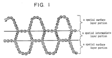
- Fig. 1 is a schematic view of a cross section of a cushioning structure obtained in Example 1.
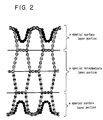
- Fig. 2 is a schematic view of a cross section of a cushioning structure obtained in Example 2.
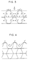
- Fig. 3 is a schematic view of a cross section of a portion in which two layers having communicating hollow portions are formed in an intermediate layer portion of the cushioning structure of this invention.
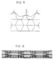
- Fig. 4 is a schematic view of a state where a woven fabric using stretchable bulky yarns is integrally fabricated between the tops of the protuberances in the surface layer portion by the woven texture on the surface layer portion of the cushioning structure of this invention.
- Fig. 5 is a schematic view of a cross section in a state where a pressure is partially exerted in the state shown in Figure 4.
- Fig. 6 is a schematic view of a cross section of a woven fabric (not shrunk) obtained in Example 2.
- the cushioning structure of this invention is a three-dimensional structure obtained by texturing a woven fabric of filament fibers and formed of a spatial surface layer portion and a spatial intermediate layer portion, said surface layer portion having a structure that it is integrally formed on one side or both sides of the intermediate layer portion.
- Said cushioning structure is characterized in that protuberances having a fixed size and a fixed shape are formed on the surface layer portion, and the intermediate layer portion is formed of one or more layers each having a plurality of communicating hollow portions which are arranged in parallel unidirectionally.
- the three-dimensional multiple woven texture of this invention is substantially formed of a filament fiber.
- a filament fiber may be an ordinary fiber.
- the fiber include a polyester fiber, a polyamide fiber (nylon fiber), an aromatic polyamide fiber, a polyvinyl alcohol fiber, a polypropylene fiber, a polyethylene fiber and a glass fiber. These fibers can be used in combination of two or more. Especially, it is preferred to use a combination of the nylon fiber and the polyester fiber.
- the filament of the filament fiber is a monofilament or a multifilament.
- a warp filament constituting the monofilament is a nylon filament excellent in deformation recovery.
- the cushioning structure which is the three-dimensional multiple woven texture of this invention has the surface layer portion in which protuberances are formed on one side or both sides thereof.
- the protuberances may be unidirectional protuberances, i.e., wavy protuberances or trapezoidal protuberances. It is desirous that the cross section of the protuberance takes a shape of a gentle curve. It is advisable that the shape of the protuberance on the surface is regularly formed such that a depression formed between the two adjacent protuberances on the surface has an inverse protuberance shape.
- the protuberances on the surface layer portion may be, as shown in Figure 1, formed on both sides or on one side only.
- the protuberance can take a wavy shape, as shown in Figure 1, which is formed unidirectionally.
- a height of the protuberance corresponds to a straight distance from the surface of the intermediate layer portion in contact with the protuberance to the top of the protuberance. It is on the average 2 to 15 mm, preferably 3 to 13 mm.
- the width of one side of the protuberance (on the average a straight distance between the tops of the two adjacent protuberances) is on the average 2 to 30 mm, preferably 3 to 25 mm.
- the ratio of height of the protuberance/width of one side of the protuberance is 1/5 to 2/1, preferably 1/4 to 3/2.
- the height of the protuberance is 1/3 or less, preferably 1/4 or less of the thickness of the cushioning structure.
- the pressure is hardly distributed uniformly.
- the cushioning structure tends to bend and collapse due to the pressure. This is, therefore, undesirable.
- the width of one side of the protuberance is less than 2 mm, the surface layer portion becomes too flat, and the pressure is hardly distributed uniformly.
- the width of one side of the protuberance exceeds 30 mm, the pressure is likewise hardly distributed uniformly.
- the woven fabric forming the surface layer portion is, as shown in Figs. 1 and 2, integrally woven texturally into the surface of the intermediate layer portion on the bottom of the protuberance.
- the cushioning structure formed of the three-dimensional multiple woven texture of this invention has the intermediate layer portion as shown in Figures 1 and 2.
- the intermediate layer portion may be formed of single layer as shown in Figure 1, two layers as shown in Figure 2 or three layers. In case of two or more layers, the layers are integrally laminated. From the aspects of ease of the production and practical use, it is suitable that the intermediate layer portion is formed of two or three layers.
- the one layer forming the intermediate layer portion has a plurality of communicating hollow portions which are arranged in parallel unidirectionally in the cross section.
- the shape of the cross section intersecting perpendicularly to the longitudinal direction, of the communicating hollow portion is approximately trapezoidal, which is advantageous for cushioning properties and durability. It is advisable that the trapezoid in the cross section is so designed that the two trapezoids next to each other form together a parallelogram and the parallelogram is repeated as one unit in one layer.
- Figure 3 is a schematic view of a cross section of a portion formed by laminating two layers having communicating hollow portions in the intermediate layer portion.
- a trapezoid (X) surrounded by four sides A, B, B' and D is formed.
- the same trapezoid (Y) is formed by four sides A'', B'', B''' and D'.
- a trapezoid of the same shape as that of these trapezoids is formed inversely between the trapezoids (X) and (Y).
- the respective trapezoids are symmetrically formed via sides D and D' (laminating surfaces).
- the plurality of the hollow portions that communicate in the intermediate layer portion are present in parallel unidirectionally.
- one hollow portion does not necessarily communicate completely from one end to another in the cushioning structure. That is, the hollow portion may be closed in one part by stitching, sewing with a machine or the like so far as a performance as a structure is maintained, and it is sufficient that the communicating hollow portions may usually communicate with one another with a length of 5 cm or more, preferably 10 cm or more.
- the number of the layers having the plurality of the communicating hollow portions in the intermediate layer portion is 1 to 5, preferably 1 to 3, and the surface layer portions having the protuberances are formed on one side or both sides, preferably both sides, of the intermediate layer portion.
- the practical thickness of the structure is 10 to 50 mm, preferably 15 to 40 mm. For special usages, the structure may be thicker.
- the intermediate layer portion is preferably formed of two or three layers.
- the cushioning structure of this invention is formed substantially of filament fibers and three-dimensionally textured. Accordingly, the space ratio is as high as 90 % or more, preferably 93 % or more. Therefore, the cushioning structure is very light in weight as a whole and easy to carry.
- a compression pressure required to compress said cushioning structure in the thickness direction by 10 mm is 20 to 300 g/cm 2 , preferably 30 to 250 g/cm 2 , and an air permeability is at least 20 cc/cm 2 ⁇ sec, preferably 30 to 500 g/cm 2 ⁇ sec, especially preferably 40 to 350 g/cm 2 ⁇ sec.
- the cushioning structure of this invention has both the suitable compression pressure and the excellent air permeability. Therefore, when the cushioning structure of this invention is used, for example, as bed, a wet feeling is reduced and a pressure is suitably distributed uniformly, to thereby give a comfortable feeling in bed. Particularly, when the cushioning structure is used as bed for patients requiring a long-term medical care, it is hygienically good and effective for prevention against bedsore.
- the cushioning structure in which the woven fabric using stretchable bulky yarns as a warp or a warp and a weft are integrally fabricated in the protuberances on the surface of the surface layer portion having the protuberances formed thereon by the woven texture feels soft in touching the surface, gives a soft feeling in contact with a body, and is therefore much superior as a cushioning material.
- an apparent length for forming the two adjacent protuberances of the surface layer portion is longer by 10 to 100 %, preferably 15 to 90 % than an apparent length for forming the two adjacent protuberances of the woven fabric fabricated in the surface layer portion. That is, it is preferable that the woven fabric is integrally fabricated between the tops of the two adjacent protuberances in the surface layer portion in such a state that the woven fabric is bridged therebetween in a depressed state which is gentler than the depressed state formed by said two protuberances.
- the stretchable bulky yarns of the woven fabric fabricated in the surface layer portion are woven in a crimped state (i.e., in a state where the crimp is developed) between the two adjacent protuberances.
- Figures 4 and 5 are schematic views of a cross section in a state where a surface layer portion having protuberances is formed on one side of an intermediate layer portion obtained by laminating two layers having communicating hollow portions and a woven fabric formed of stretchable bulky yarns is integrally fabricated between the tops of the protuberances on the surface layer portion by the woven texture.
- E, E' and E'' are the tops of the protuberances on the surface layer portion wherein the woven fabric is integrated.
- F and F' are depressions of the woven fabric formed between the two adjacent protuberances.
- Figure 4 shows a state where a pressure is not applied
- Figure 5 shows a state where a pressure is applied to the top E' of the protuberance.
- the cushioning structure of this invention is a three-dimensional woven structure which makes use of spaces of the multiple woven texture.
- This structure is quite low in fiber fillability and has a raised/depressed structure of a specific shape on the surface. Therefore, the cushioning structure is excellent in air permeability, cushioning properties, uniformity of pressure distribution and washability. Accordingly, the cushioning structure of this invention is suited for bed pad, pillow, chair, vehicle sheet and the like.
- the cushioning structure of this invention is a flat material having a thickness of about 10 to 50 mm, it can be used as a cushioning material of a bed pad.
- a cushioning structure of a predetermined size can be used as a cushioning material for bed pad by accommodating it into a cover of an ordinary cloth.
- the cushioning structure is accommodated within a cover having an air permeability of 5 cc/cm 2 ⁇ sec or less.
- a cushioning structure having a thickness of 20 to 40 mm, especially 25 to 35 mm is suitable for bed pad.
- the cushioning structure may be directly laid on a bed pad or on a bed pad stuffed with short fibers or cotton. Or the cushioning structure may be laid on a carpet. In this case, too, it feels also quite comfortable.
- the cushioning structure of this invention is, as mentioned above, quite excellent in air permeability and excellent in uniformity of pressure distribution. Consequently, when said cushioning structure is used as a cushioning material for bed pad, it provides a comfortable feeling in bed but not a wet feeling in bed.
- the cushioning material for bed pad using the cushioning structure of this invention is quite effective for prevention against a bedsore of a patient who has to undergo long-term medical care in bed.
- a change of his posture is usually required every 2 or 3 hours with the conventional bed pad.
- the bed pad using the cushioning structure of this invention is employed, no substantial bedsore is observed even if the posture is changed every 4 or 5 hours. This shows that the cushioning structure of this invention is quite excellent in air permeability and excellent in uniformity of pressure distribution.
- the cushioning structure of this invention is quite excellent in durability. For example, when the cushioning structure of this invention is used every day as a cushioning material for bed pad, no substantial change is observed, after three or more years, with respect to the compression pressure and the uniformity of pressure distribution.
- Air permeability was measured with JISL-1079 (Frazier-type air permeability tester). Air was drawn in such that a pressure difference became 1/2 inch, and an amount of flowing air per unit area and unit time on that occasion was taken as the air permeability.
- a stress distribution of a sacrum portion was measured with a TEX ⁇ SCAN tactile sensor system manufactured by Nitta K.K.
- the pressure sensor has a size of 43 cm x 48 cm, and has an ability to measure a pressure at each of spots by 10 mm apart.
- a sample material was compressed at a rate of 50 mm/min using a compression disc described in JISK-6401-5.4.2, and the pressure was measured when the sample was compressed by 10 mm.
- Loading and unloading of a 200 kg weight in an area having a diameter of 20 cm was repeated 50,000 times, and a change in thickness before and after the test was measured. A degree of collapse was shown by a ratio (%) of the decreased thickness to the thickness before measured.
- a copolyethylene terephthalate fiber containing 13 mol%, based on the total acid components, of an isophthalic acid component was used as a highly shrinkable yarn.
- a denier of a monofilament in this yarn was 4, a total denier was 1,000, an intrinsic viscosity [ ⁇ ] was 0.8, a strength was 5.5 g/de, a thermal shrinkage stress value was 0.52 g/de, and a boiling-off water shrinkage factor was 47 % (using SOCRATEX, a trade name for a yarn manufactured by Teijin Limited).
- the woven fabric was set at a dry heat of 170°C and the highly shrinkable yarns as the warp were shrunk to obtain a highly air-permeable cushioning structure having a thickness of 25 mm, a cross sectional shape of said structure being shown in Figure 1.
- a white circle (0) shows a polyethylene terephthalate monofilament (weft) having a denier of 400, and a warp woven in the white circle shows a nylon monofilament having a denier of 440.
- Two solid lines which were drawn in parallel laterally, as shown in Figure 1, show originally highly shrinkable yarns which have been shrunk, and the intermediate layer portion (single layer) was formed by the two highly shrinked yarns.
- polyethylene terephthalate woollie yarns SD (144 filaments having a denier of 475) were used as a weft outer layer, and the polyethylene terephthalate monofilaments having a denier of 300 were woven in the four layers of the intermediate layer portion to obtain a woven fabric of a structure shown in Figure 6.
- the obtained woven fabric was set at 170°C for about 2 minutes, and the highly shrinkable yarns were shrunk by 40 % in the longitudinal direction of the woven fabric to obtain a highly air-permeable cushioning structure having a thickness of 30 mm, a cross sectional shape of said structure being shown in Figure 2.
- a black circle ( ⁇ ) of the weft shows a polyethylene terephthalate woollie yarn.
- a dotted line woven in the black circle is a warp of a polyethylene terephthalate woollie yarn.
- a white circle and a circle with cross show warps of polyethylene terephthalate monofilaments.
- Solid lines woven in the white circle and the circle with cross show wefts of nylon monofilaments.
- the highly shrinkable yarns (three thick solid lines drawn in parallel laterally) are formed by three layers which form an intermediate layer portion (two layers).
- the polyethylene terephthalate woollie yarns, the nylon monofilaments and the highly shrinkable yarns are integrated texturally with one another in some portions, as shown Fig. 2.
- Example 2 1 Compression pressure (g/cm 2 ) 65 40 2 Air permeability (cc/cm 2 ⁇ sec) 800 78 3 Texture fillability (%) [Space ratio %] 4 [96] 4.5 [95.5] 4 Degree of collapse (%) 5.8 4.5 5 Stress distribution All 100 g/cm 2 or less All 70 g/cm 2 or less 6 Height of a protuberance on a surface layer portion (mm) 7 4 Width of one side of the protuberance on the surface layer portion (mm) 16 16 7 Total thickness (mm) 25 30
- Portions which were 10 cm spaced apart from both ends in the longitudinal (warp) direction of the cushioning structure obtained in Example 2 were sewed with a machine.
- the longitudinal and lateral ends were subjected to a piping-Adler processing with a piping tape having a width of 70 mm (a tape obtained by laminating a urethane film having a back surface of 100 ⁇ in thickness on a back surface of a pile tricot and slitting the laminate with a width of 70 mm) with a special machine in which Adler-205 type sewing machine (a trade name for a machine manufactured by Durkoepp Adler GmbH) was fitted with a head and a V-shaped element. There was obtained a bed mattress formed of the good cushioning structure.
- polyethylene terephthalate woollie yarns SD (144 filaments having a denier of 475) were used as a weft outer layer (32.35 filaments/inch), and the polyethylene terephthalate monofilaments having a denier of 300 (60.65 monofilaments/inch) were woven in the four layers of the intermediate layer portion to obtain a woven fabric of a structure shown in Figure 6.
- the obtained woven fabric was set at 130°C for about 2 minutes, and the highly shrinkable yarns were shrunk by 38 % in the longitudinal direction of the woven fabric to obtain a highly air-permeable cushioning structure having a thickness of 30.5 mm, a cross sectional shape of said structure being shown in Figure 2.
- the properties of the obtained cushioning structure are shown in Table 2.
- Properties Example 4 1 Compression pressure (g/cm 2 ) 60 2 Air permeability (cc/cm 2 ⁇ sec) 170 3 Texture fillability (%) [Space ratio %] 3.2 [96.8] 4 Degree of collapse (%) 2.4 5 Stress distribution All 107 g/cm 2 or less 6 Height of a protuberance on a surface layer portion (mm) 4.5 Width of one side of the protuberance on the surface layer portion (mm) 16.5 7 Total thickness (mm) 30.5
- a cushioning material for bed pad having a width of 92 cm, a length of 195 cm and a thickness of 3.05 cm was prepared by using the cushioning structure obtained in Example 4. This cushioning structure was used by accommodating it into an ordinary cotton plain fabric (the density of 77 ends/inch and 140 pick/inch using cotton yarn of 40 s/1).
- the pressure distribution of the cushioning material for bed pad was measured in each of the following modes by laying said cushioning material on a carpet or on a standard bed pad which was placed on the carpet.
- a grown-up man (height 175, weight 70 kg) lied on his back on the bed pad in each mode, and a pressure sensor was placed between his hip and the bed pad. In this posture, the distribution of the pressure exerted on the hip was measured.
- a tactile sensor system GSCAN (BIG-MAT) manufactured by Nitta K.K. was used as a measuring instrument. This measuring instrument can measure the pressure exerted on the hip with a unit of 1 cm 2 .
- the cushioning structure of this invention is excellent in air permeability and uniformity of pressure distribution.
- a cushioning structure excellent in air permeability, cushioning properties, uniformity of pressure distribution, durability, washability and soft feeling to touch. It is useful as a cushioning material for use in a bed, a sheet for vehicles, a sheet for chair, a sheet for Japanese cushion, a sheet for drawing-room suite, a sports material and the like.
Description
- This invention relates to a cushioning structure constituted by a three-dimensional multiple woven texture. More specifically, this invention relates to a cushioning structure constituted by a three-dimensional multiple woven texture, which structure can be used in the fields requiring an air permeability, cushioning properties, washability and the like, such as bed, a sheet for vehicles, a sheet for chair, a sheet for Japanese cushion, a sheet for drawing-room suite, a sports material and the like.
- Three-dimensional cushioning structures have been hitherto used in various fields which are roughly classified into a resin form mat typified by an urethane mat, a cushioning fiber structure utilizing a space of a monofilament assembly and a structure of a three-dimensional woven texture utilizing a space of a multiple woven texture. However, these ordinary three-dimensional cushioning structures have defects in practical use. There is a resin foam mat, such as an urethane mat, which has a roughened surface and possesses a controlled compression pressure. Nevertheless, since the internal space is formed of a foam resin, air is not passed therethrough. Thus, the resin foam mat is lacking in air permeability. Especially, the urethane mat has a decreased compression (resistance) pressure when it is used for a long period of time, and then it becomes unusable as a cushioning structure.
- On the other hand, the cushioning fiber structure utilizing the space of the monofilament assembly is relatively good in air permeability, but is low in durability. That is, as the cushioning fiber structure is repetitively used, collapse occurs, so that an inner space (void) ratio decreases and cushioning properties are almost lost. Further, in case of the structure of the three-dimensional woven texture utilizing the space of the multiple woven texture, a durability is relatively excellent, but a fiber fillability is high, with the result that an air permeability is poor and cushioning properties are low. Besides, there is a defect that since a big uneven shape is not present on the surface, a pressure distribution hardly becomes uniform.
- The hitherto known cushioning materials are explained in detail below.
- This document describes a cushioning woven fabric characterized in that a woven material obtained by using at least two kinds of synthetic resin fibers having a sufficient potential heat shrinkage difference as a warp, or as a weft, or as a warp and a weft is heat-relaxed under suitable temperature conditions to form a wavy resilient surface portion that is formed by flexing of the synthetic resin fiber having a lower heat shrinkage, the flexing being realized by heat shrinkage of the synthetic resin fiber having a higher heat shrinkage to the higher extent. This cushioning woven fabric is either a single-woven cushioning material having a wavy surface or a double-woven, sheet-like cushioning material in which pipy space portions formed by flexing are arranged in parallel and whose both surfaces are flat. The structure of this cushioning material is at most a structure of a monolayered wavy woven fabric, and has poor cushioning properties and insufficient pressure distribution and lacks a durability.
- This document describes a shoes mat whose surface material is formed of a cushioning woven fabric in which at least two kinds of synthetic resin fibers having a sufficient potential heat shrinkage difference are used, and a wavy resilient portion is formed by flexing of the synthetic resin fiber having a lower heat shrinkage, the flexing being realized by heat shrinking of the synthetic fiber having a higher heat shrinkage to the higher extent. This cushioning woven fabric is obtained by simply heat-treating a plain fabric or a gauze fabric, and has a thickness of at most about 5 mm. Accordingly, cushioning properties of the fabric are very poor, and said fabric is quite unsuitable as a cushioning material for bed pad or vehicle sheet.
- This document describes a cloth of a three-dimensional structure in which fabric textures of front and back surfaces are connected with connecting yarns and which is knitted with a double raschel knitting machine or a moquette knitting machine, the connecting yarns being two or more kinds of yarns each having heat shrinkage different from the other by at least 5 %, the space ratio of the cloth being 0.4 to 0.98, and the thickness of the cloth being 1 to 15 mm, as well as a cloth of a three-dimensional structure which is obtained by heat-treating the above cloth to develop an uneven appearance. In the above cloth of the three-dimensional structure, the fabric textures of the front and back surfaces are connected with the connecting yarns, the yarns each having the heat shrinkage different from the other are used, the yarns are subjected to heat-shrinkage thereby to form the raised and depressed portions on the surface. Basically, this cloth is a relatively thin structure formed of the front and back fabrics. A cloth having a thickness of 6.5 mm is actually shown in the document. This document indicates that the above cloth is used as a surface material for a mattress, a sheet, a bed pad and clothing. Accordingly, the cloth is thin and has low cushioning properties.
- This document includes the description about "a narrow woven tubular fabric having a flattened oval cross-section, said fabric comprising an upper layer and a lower layer, both of said layers containing monofilament filling yarns, said monofilament filling yarns having a denier between 100 to 2080, said layers being connected together along their longitudinal edges and said layers being resiliently separated by a plurality of monofilament warp yarns alternately intermittently woven with each of said layers, said monofilament warp yarns having a denier of between 100 to 2080, the sum of the denier of a monofilament filling yarn plus a monofilament warp yarn being in the range of from 430 denier to 4200 denier and the ratio of denier of monofilament filling yarn to monofilament warp yarn being from 20:1 to 1:20."
- In brief, the above invention relates to a narrow woven tubular fabric with two layers resiliently separated from one another to provide a cushion or sponge effect. This fabric is used in shoulder straps of brassieres, straps on knapsacks or back-packing equipment or straps on scuba diving equipment. Accordingly, the above fabric is a narrow structure such as a strap, and has low cushioning properties. Thus, the fabric cannot be used as a cushioning material for a bed pad or vehicle sheet.
- FR-A-2063535, which represents the most relevant state of the art, describes a multi-layer expandable fabric for use in a composite structure such as rigid cellular panels, panels of reinforced foam or inflatable structures. The multi-layer expandable fabric is characterized by excellent compressive and shearing strength and is of one-piece including at least two upper and lower woven outer layers interconnected by non-woven thread plies transverse to the outer layers. The threads of the transverse plies are continuous and have a laid-out length equal to the width of the flat fabric and occupy an oblique position relative to the mid-plane of the fabric in the expanded state.
- As noted above, the ordinary cushioning structures, when used in beds, sheets for vehicles, sheets for chairs, sheets for Japanese cushions, sports material and the like, were not said to satisfy such conditions required of the cushioning structure that heat or sweat generated from a human body is absorbed, durability is provided and pressure distribution is uniform.
- It is a first object of this invention to provide a cushioning structure having a new structure that solves the defects associated with the cushioning structures in the above prior arts.
- A second object of this invention is to provide a cushioning structure excellent in cushioning properties, uniformity of a pressure distribution without causing a bottom-hit feel, air permeability, washability and durability.
- A third object of this invention is to provide a cushioning structure which is relatively light in weight and can be used for widely differing applications such as beds, sheets for vehicles, sheets for chairs, sheets for Japanese cushions, drawing-room suites, sports material and the like.
- According to the researches of the present inventors, it has been found that the objects of this invention are achieved by a cushioning structure which is a three-dimensional multiple woven texture constituted by a spatial surface layer portion and a spatial intermediate layer portion, said surface layer portion having a structure that is integrally formed on one side or both sides of the spatial intermediate layer portion, wherein protuberances are formed on said one side or both sides of the surface layer portion at least unidirectionally, characterised in that said protuberances have an average height of 2 to 15 mm, an average width of one side of the protuberance being 2 to 30 mm; in that said intermediate layer portion is formed of one or more layers, each layer having a plurality of communicating hollow portions which are arranged in parallel unidirectionally, and a cross section, perpendicular to the longitudinal direction, of the communicating hollow portion in the intermediate layer portion having the shape of a trapezoid; and in that the surface layer portion is integrally woven into the surface of the intermediate layer portion.
- Fig. 1 is a schematic view of a cross section of a cushioning structure obtained in Example 1. Fig. 2 is a schematic view of a cross section of a cushioning structure obtained in Example 2. Fig. 3 is a schematic view of a cross section of a portion in which two layers having communicating hollow portions are formed in an intermediate layer portion of the cushioning structure of this invention. Fig. 4 is a schematic view of a state where a woven fabric using stretchable bulky yarns is integrally fabricated between the tops of the protuberances in the surface layer portion by the woven texture on the surface layer portion of the cushioning structure of this invention. Fig. 5 is a schematic view of a cross section in a state where a pressure is partially exerted in the state shown in Figure 4. Fig. 6 is a schematic view of a cross section of a woven fabric (not shrunk) obtained in Example 2.
- The cushioning structure of this invention is a three-dimensional structure obtained by texturing a woven fabric of filament fibers and formed of a spatial surface layer portion and a spatial intermediate layer portion, said surface layer portion having a structure that it is integrally formed on one side or both sides of the intermediate layer portion. Said cushioning structure is characterized in that protuberances having a fixed size and a fixed shape are formed on the surface layer portion, and the intermediate layer portion is formed of one or more layers each having a plurality of communicating hollow portions which are arranged in parallel unidirectionally.
- The three-dimensional multiple woven texture of this invention is substantially formed of a filament fiber. Such a fiber may be an ordinary fiber. Examples of the fiber include a polyester fiber, a polyamide fiber (nylon fiber), an aromatic polyamide fiber, a polyvinyl alcohol fiber, a polypropylene fiber, a polyethylene fiber and a glass fiber. These fibers can be used in combination of two or more. Especially, it is preferred to use a combination of the nylon fiber and the polyester fiber. The filament of the filament fiber is a monofilament or a multifilament. A warp filament constituting the monofilament is a nylon filament excellent in deformation recovery.
- The cushioning structure which is the three-dimensional multiple woven texture of this invention has the surface layer portion in which protuberances are formed on one side or both sides thereof. The protuberances may be unidirectional protuberances, i.e., wavy protuberances or trapezoidal protuberances. It is desirous that the cross section of the protuberance takes a shape of a gentle curve. It is advisable that the shape of the protuberance on the surface is regularly formed such that a depression formed between the two adjacent protuberances on the surface has an inverse protuberance shape.
- The protuberances on the surface layer portion may be, as shown in Figure 1, formed on both sides or on one side only. The protuberance can take a wavy shape, as shown in Figure 1, which is formed unidirectionally. A height of the protuberance corresponds to a straight distance from the surface of the intermediate layer portion in contact with the protuberance to the top of the protuberance. It is on the average 2 to 15 mm, preferably 3 to 13 mm. The width of one side of the protuberance (on the average a straight distance between the tops of the two adjacent protuberances) is on the average 2 to 30 mm, preferably 3 to 25 mm. The ratio of height of the protuberance/width of one side of the protuberance is 1/5 to 2/1, preferably 1/4 to 3/2.
- It is desirable that the height of the protuberance is 1/3 or less, preferably 1/4 or less of the thickness of the cushioning structure. When the height of the protuberance is lower than 2 mm, the pressure is hardly distributed uniformly. On the other hand, when it exceeds 15 mm, the cushioning structure tends to bend and collapse due to the pressure. This is, therefore, undesirable. When the width of one side of the protuberance is less than 2 mm, the surface layer portion becomes too flat, and the pressure is hardly distributed uniformly. On the other hand, when the width of one side of the protuberance exceeds 30 mm, the pressure is likewise hardly distributed uniformly.
- The woven fabric forming the surface layer portion is, as shown in Figs. 1 and 2, integrally woven texturally into the surface of the intermediate layer portion on the bottom of the protuberance.
- The cushioning structure formed of the three-dimensional multiple woven texture of this invention has the intermediate layer portion as shown in Figures 1 and 2. The intermediate layer portion may be formed of single layer as shown in Figure 1, two layers as shown in Figure 2 or three layers. In case of two or more layers, the layers are integrally laminated. From the aspects of ease of the production and practical use, it is suitable that the intermediate layer portion is formed of two or three layers.
- The one layer forming the intermediate layer portion has a plurality of communicating hollow portions which are arranged in parallel unidirectionally in the cross section. The shape of the cross section intersecting perpendicularly to the longitudinal direction, of the communicating hollow portion is approximately trapezoidal, which is advantageous for cushioning properties and durability. It is advisable that the trapezoid in the cross section is so designed that the two trapezoids next to each other form together a parallelogram and the parallelogram is repeated as one unit in one layer.
- In case of laminating two or three layers having the plurality of the communicating hollow portions, it is more preferable for cushioning properties and durability that the cross sectional shapes of the communicating hollow portions are symmetrical about the laminating surface in the laminating direction. This is specifically explained below by referring to Figure 3.
- Figure 3 is a schematic view of a cross section of a portion formed by laminating two layers having communicating hollow portions in the intermediate layer portion. In Figure 3, a trapezoid (X) surrounded by four sides A, B, B' and D is formed. The same trapezoid (Y) is formed by four sides A'', B'', B''' and D'. A trapezoid of the same shape as that of these trapezoids is formed inversely between the trapezoids (X) and (Y). On the layer under the layer in which the trapezoids (X) and (Y) are formed, the respective trapezoids are symmetrically formed via sides D and D' (laminating surfaces).
- For example, in Figure 3, when a pressure is exerted on the upper surface of the intermediate layer portion as shown by a white arrow, the pressure is applied in a left direction on the sides B, B'', C and C'', while the pressure is applied in a right direction on the sides B', B"', C' and C"'. Thus, the individual sides are curled, as shown in dotted lines, toward the outside of the trapezoids. The whole cushioning properties are exhibited by the curling force. On the other hand, the force is applied internally (in the arrow direction) to the sides D and D', but filament yarns obtained by shrinking highly shrinkable yarns are not elongated on the sides D and D', with the consequence a fiber hardly causes a fatigue and has a durability. Meanwhile, monofilament yarns (warps or warps and wefts) of the portions A and A'' are textured, and though a pulling force is applied thereto, they are hard to flow. Accordingly, that the cross sectional shape of the communicating hollow portion in the intermediate layer portion is trapezoidal and the plurality of the communicating hollow portions are gathered and laminated to form a honeycomb structure as a whole is considered to contribute to exhibiting the cushioning properties and the durability of the cushioning structure.
- In the communicating hollow portions in the intermediate layer portion, the plurality of the hollow portions that communicate in the intermediate layer portion are present in parallel unidirectionally. However, one hollow portion does not necessarily communicate completely from one end to another in the cushioning structure. That is, the hollow portion may be closed in one part by stitching, sewing with a machine or the like so far as a performance as a structure is maintained, and it is sufficient that the communicating hollow portions may usually communicate with one another with a length of 5 cm or more, preferably 10 cm or more. Especially, there can be also achieved an effect that removal of a filament yarn from the end relative to the communicating direction of the hollow portion can be prevented by closing the hollow portion at the end of the cushioning structure through sewing with a machine.
- In the cushioning structure of this invention, the number of the layers having the plurality of the communicating hollow portions in the intermediate layer portion is 1 to 5, preferably 1 to 3, and the surface layer portions having the protuberances are formed on one side or both sides, preferably both sides, of the intermediate layer portion. The practical thickness of the structure is 10 to 50 mm, preferably 15 to 40 mm. For special usages, the structure may be thicker. Especially as a cushioning structure for bed pad, the intermediate layer portion is preferably formed of two or three layers.
- The cushioning structure of this invention is formed substantially of filament fibers and three-dimensionally textured. Accordingly, the space ratio is as high as 90 % or more, preferably 93 % or more. Therefore, the cushioning structure is very light in weight as a whole and easy to carry.
- Further, in the cushioning structure of this invention, a compression pressure required to compress said cushioning structure in the thickness direction by 10 mm is 20 to 300 g/cm2, preferably 30 to 250 g/cm2, and an air permeability is at least 20 cc/cm2·sec, preferably 30 to 500 g/cm2·sec, especially preferably 40 to 350 g/cm2·sec. Thus, the cushioning structure of this invention has both the suitable compression pressure and the excellent air permeability. Therefore, when the cushioning structure of this invention is used, for example, as bed, a wet feeling is reduced and a pressure is suitably distributed uniformly, to thereby give a comfortable feeling in bed. Particularly, when the cushioning structure is used as bed for patients requiring a long-term medical care, it is hygienically good and effective for prevention against bedsore.
- According to the researches of the present inventors, it has been found that the cushioning structure in which the woven fabric using stretchable bulky yarns as a warp or a warp and a weft are integrally fabricated in the protuberances on the surface of the surface layer portion having the protuberances formed thereon by the woven texture feels soft in touching the surface, gives a soft feeling in contact with a body, and is therefore much superior as a cushioning material.
- When the woven fabric is thus further integrated with the surface layer portion having the protuberances, it is advisable that in the cross section of the surface layer portion, an apparent length for forming the two adjacent protuberances of the surface layer portion is longer by 10 to 100 %, preferably 15 to 90 % than an apparent length for forming the two adjacent protuberances of the woven fabric fabricated in the surface layer portion. That is, it is preferable that the woven fabric is integrally fabricated between the tops of the two adjacent protuberances in the surface layer portion in such a state that the woven fabric is bridged therebetween in a depressed state which is gentler than the depressed state formed by said two protuberances. Besides, it is especially preferable that the stretchable bulky yarns of the woven fabric fabricated in the surface layer portion are woven in a crimped state (i.e., in a state where the crimp is developed) between the two adjacent protuberances.
- When the structure in which the woven fabric formed of the stretchable bulky yarns is fabricated in the surface layer portion in the above-mentioned state is used as a cushioning material and when a pressure is exerted on such structure, the pressure is uniformly distributed as a whole and a pressure resistance is distributed uniformly in a wide region even if one of the protuberances is independently deforms due to the pressure; this is because the length of the surface of the woven fabric is properly short and the woven fabric is crimped. This is explained below by referring to Figures 4 and 5.
- Figures 4 and 5 are schematic views of a cross section in a state where a surface layer portion having protuberances is formed on one side of an intermediate layer portion obtained by laminating two layers having communicating hollow portions and a woven fabric formed of stretchable bulky yarns is integrally fabricated between the tops of the protuberances on the surface layer portion by the woven texture. In Figures 4 and 5, E, E' and E'' are the tops of the protuberances on the surface layer portion wherein the woven fabric is integrated. F and F' are depressions of the woven fabric formed between the two adjacent protuberances. Figure 4 shows a state where a pressure is not applied, and Figure 5 shows a state where a pressure is applied to the top E' of the protuberance. In Figure 5, the shape of the top E' of the protuberance bends and collapses, but the depressions F and F' of the woven fabric rise, and the structure flattens owing to the pressure. Thus, the force to pull the top of the adjacent protuberances E and E'' is applied to the surface of the woven fabric, whereby the pressure is distributed uniformly.
- The cushioning structure of this invention is a three-dimensional woven structure which makes use of spaces of the multiple woven texture. This structure is quite low in fiber fillability and has a raised/depressed structure of a specific shape on the surface. Therefore, the cushioning structure is excellent in air permeability, cushioning properties, uniformity of pressure distribution and washability. Accordingly, the cushioning structure of this invention is suited for bed pad, pillow, chair, vehicle sheet and the like.
- In particular, since the cushioning structure of this invention is a flat material having a thickness of about 10 to 50 mm, it can be used as a cushioning material of a bed pad. In this case, a cushioning structure of a predetermined size can be used as a cushioning material for bed pad by accommodating it into a cover of an ordinary cloth. For heat insulation, it is advisable that the cushioning structure is accommodated within a cover having an air permeability of 5 cc/cm2·sec or less. A cushioning structure having a thickness of 20 to 40 mm, especially 25 to 35 mm is suitable for bed pad. The cushioning structure may be directly laid on a bed pad or on a bed pad stuffed with short fibers or cotton. Or the cushioning structure may be laid on a carpet. In this case, too, it feels also quite comfortable.
- Further, the cushioning structure of this invention is, as mentioned above, quite excellent in air permeability and excellent in uniformity of pressure distribution. Consequently, when said cushioning structure is used as a cushioning material for bed pad, it provides a comfortable feeling in bed but not a wet feeling in bed.
- In particular, the cushioning material for bed pad using the cushioning structure of this invention is quite effective for prevention against a bedsore of a patient who has to undergo long-term medical care in bed. In order to prevent the bedsore of the patient under the long-term medical care in bed, a change of his posture is usually required every 2 or 3 hours with the conventional bed pad. However, when the bed pad using the cushioning structure of this invention is employed, no substantial bedsore is observed even if the posture is changed every 4 or 5 hours. This shows that the cushioning structure of this invention is quite excellent in air permeability and excellent in uniformity of pressure distribution.
- Further, the cushioning structure of this invention is quite excellent in durability. For example, when the cushioning structure of this invention is used every day as a cushioning material for bed pad, no substantial change is observed, after three or more years, with respect to the compression pressure and the uniformity of pressure distribution.
- This invention will be illustrated specifically by referring to the following Examples. In the Examples, the following properties were measured by apparatus and conditions mentioned below.
- Air permeability was measured with JISL-1079 (Frazier-type air permeability tester). Air was drawn in such that a pressure difference became 1/2 inch, and an amount of flowing air per unit area and unit time on that occasion was taken as the air permeability.
- A stress distribution of a sacrum portion was measured with a TEX·SCAN tactile sensor system manufactured by Nitta K.K. The pressure sensor has a size of 43 cm x 48 cm, and has an ability to measure a pressure at each of spots by 10 mm apart.
- A sample material was compressed at a rate of 50 mm/min using a compression disc described in JISK-6401-5.4.2, and the pressure was measured when the sample was compressed by 10 mm.
- Loading and unloading of a 200 kg weight in an area having a diameter of 20 cm was repeated 50,000 times, and a change in thickness before and after the test was measured. A degree of collapse was shown by a ratio (%) of the decreased thickness to the thickness before measured.
- A copolyethylene terephthalate fiber containing 13 mol%, based on the total acid components, of an isophthalic acid component was used as a highly shrinkable yarn. A denier of a monofilament in this yarn was 4, a total denier was 1,000, an intrinsic viscosity [η] was 0.8, a strength was 5.5 g/de, a thermal shrinkage stress value was 0.52 g/de, and a boiling-off water shrinkage factor was 47 % (using SOCRATEX, a trade name for a yarn manufactured by Teijin Limited).
- As a warp, two layers of the highly shrinkable yarns (each layer 19 ends/inch) in an intermediate layer portion and three layers of nylon monofilaments having a denier of 440 (each layer 36 filaments/inch) were respectively wound on two beams, and a warp of four-fold weave was prepared using the double-beams. As a weft, four layers all formed of polyethylene terephthalate monofilaments having a denier of 400 (each layer 36 ends/inch) were used. The thus obtained warp and weft were woven. The woven fabric was set at a dry heat of 170°C and the highly shrinkable yarns as the warp were shrunk to obtain a highly air-permeable cushioning structure having a thickness of 25 mm, a cross sectional shape of said structure being shown in Figure 1.
- In Figure 1, a white circle (0) shows a polyethylene terephthalate monofilament (weft) having a denier of 400, and a warp woven in the white circle shows a nylon monofilament having a denier of 440. Two solid lines which were drawn in parallel laterally, as shown in Figure 1, show originally highly shrinkable yarns which have been shrunk, and the intermediate layer portion (single layer) was formed by the two highly shrinked yarns.
- As a warp, three layers of the same highly shrinkable yarns (total denier 1,000) as those used in Example 1 (each layer 19 ends/inch) in an intermediate layer portion, four layers of nylon monofilaments having a denier of 330 (each layer 36 ends/inch), and polyethylene terephthalate woollie yarns SD (144 filaments having a denier of 475: KG156W supplied by Teijin Limited) as outermost layers (each layer 36 yarns/inch) were respectively wound on three beams, and a modified five-fold weave was formed by the triple beams with a Rapier loom (having a dobby). At this time, polyethylene terephthalate woollie yarns SD (144 filaments having a denier of 475) were used as a weft outer layer, and the polyethylene terephthalate monofilaments having a denier of 300 were woven in the four layers of the intermediate layer portion to obtain a woven fabric of a structure shown in Figure 6. The obtained woven fabric was set at 170°C for about 2 minutes, and the highly shrinkable yarns were shrunk by 40 % in the longitudinal direction of the woven fabric to obtain a highly air-permeable cushioning structure having a thickness of 30 mm, a cross sectional shape of said structure being shown in Figure 2.
- In Figure 2 (also in Figure 6), a black circle () of the weft shows a polyethylene terephthalate woollie yarn. A dotted line woven in the black circle is a warp of a polyethylene terephthalate woollie yarn. A white circle and a circle with cross (x mark inside the white circle) show warps of polyethylene terephthalate monofilaments. Solid lines woven in the white circle and the circle with cross show wefts of nylon monofilaments. The highly shrinkable yarns (three thick solid lines drawn in parallel laterally) are formed by three layers which form an intermediate layer portion (two layers). The polyethylene terephthalate woollie yarns, the nylon monofilaments and the highly shrinkable yarns are integrated texturally with one another in some portions, as shown Fig. 2.
- The properties of the cushioning structures obtained in Examples 1 and 2 are shown in Table 1.
Properties Example 1 Example 2 1 Compression pressure (g/cm2) 65 40 2 Air permeability (cc/cm2·sec) 800 78 3 Texture fillability (%) [Space ratio %] 4 [96] 4.5 [95.5] 4 Degree of collapse (%) 5.8 4.5 5 Stress distribution All 100 g/cm2 or less All 70 g/cm2 or less 6 Height of a protuberance on a surface layer portion (mm) 7 4 Width of one side of the protuberance on the surface layer portion (mm) 16 16 7 Total thickness (mm) 25 30 - Portions which were 10 cm spaced apart from both ends in the longitudinal (warp) direction of the cushioning structure obtained in Example 2 were sewed with a machine. The longitudinal and lateral ends were subjected to a piping-Adler processing with a piping tape having a width of 70 mm (a tape obtained by laminating a urethane film having a back surface of 100 µ in thickness on a back surface of a pile tricot and slitting the laminate with a width of 70 mm) with a special machine in which Adler-205 type sewing machine (a trade name for a machine manufactured by Durkoepp Adler GmbH) was fitted with a head and a V-shaped element. There was obtained a bed mattress formed of the good cushioning structure.
- Removal of the yarn at the end was not observed in this bed mattress. As to the properties, the air permeability was 76 cc/cm2·sec, and the other properties were almost the same as those in Example 2.
- As a warp, three layers of the same highly shrinkable yarns (total denier 1,000) as those used in Example 1 (each layer 19 ends/inch) in an intermediate layer portion, four layers of nylon monofilaments having a denier of 440 (each layer 36 ends/inch), and polyethylene terephthalate woollie yarns SD (144 filaments having a denier of 475: KG156W supplied by Teijin Ltd.) as outermost layers (each layer 36 ends/inch) were respectively wound on three beams, and a modified five-fold weave (9 layers) was formed by the triple beams with a Rapier loom (having a dobby). At this time, polyethylene terephthalate woollie yarns SD (144 filaments having a denier of 475) were used as a weft outer layer (32.35 filaments/inch), and the polyethylene terephthalate monofilaments having a denier of 300 (60.65 monofilaments/inch) were woven in the four layers of the intermediate layer portion to obtain a woven fabric of a structure shown in Figure 6. The obtained woven fabric was set at 130°C for about 2 minutes, and the highly shrinkable yarns were shrunk by 38 % in the longitudinal direction of the woven fabric to obtain a highly air-permeable cushioning structure having a thickness of 30.5 mm, a cross sectional shape of said structure being shown in Figure 2. The properties of the obtained cushioning structure are shown in Table 2.
Properties Example 4 1 Compression pressure (g/cm2) 60 2 Air permeability (cc/cm2·sec) 170 3 Texture fillability (%) [Space ratio %] 3.2 [96.8] 4 Degree of collapse (%) 2.4 5 Stress distribution All 107 g/cm2 or less 6 Height of a protuberance on a surface layer portion (mm) 4.5 Width of one side of the protuberance on the surface layer portion (mm) 16.5 7 Total thickness (mm) 30.5 - A cushioning material for bed pad having a width of 92 cm, a length of 195 cm and a thickness of 3.05 cm was prepared by using the cushioning structure obtained in Example 4. This cushioning structure was used by accommodating it into an ordinary cotton plain fabric (the density of 77 ends/inch and 140 pick/inch using cotton yarn of 40 s/1).
- The pressure distribution of the cushioning material for bed pad was measured in each of the following modes by laying said cushioning material on a carpet or on a standard bed pad which was placed on the carpet.
- A grown-up man (height 175, weight 70 kg) lied on his back on the bed pad in each mode, and a pressure sensor was placed between his hip and the bed pad. In this posture, the distribution of the pressure exerted on the hip was measured. A tactile sensor system GSCAN (BIG-MAT) manufactured by Nitta K.K. was used as a measuring instrument. This measuring instrument can measure the pressure exerted on the hip with a unit of 1 cm2.
- The modes of the cushioning structure are shown below.
- Mode 1:
- a carpet only
- Mode 2:
- a combination of a carpet and a standard bed pad placed thereon
- Mode 3:
- a combination of a carpet and the cushioning material for bed pad placed thereon
- Mode 4:
- a combination of a carpet, a standard bed pad placed on the carpet and the cushioning material for bed pad placed on the standard bed pad
- In this measurement, there were used a needle punch carpet having a width of 92 cm, a length of 195 cm and a thickness of 5 mm and a standard bed pad obtained by uniformly packing a cotton into a cloth bag and having a width of 92 cm, a length of 195 cm, a thickness of 7 cm (no load), and a weight of 5.8 kg. The results are shown in Table 3. In the Table 3, the figures indicate areas (cm2) that responded to the respective pressures (g/cm2).

- The above Table 3 reveals that in modes 3 and 4 using the cushioning structure of this invention, the pressure is widely distributed as compared to the other modes not using the cushioning structure of this invention. That is, in regard to the total of the unit area (cm2) to which a great load (e.g., greater than 107 g/cm2) is exerted, mode 3 is reduced compared with mode 1, and mode 4 is much reduced compared with mode 2.
- Five patients who have to be under medical care in bed and cannot change their postures by themselves used the cushioning structure of this invention as a bed pad, and the effect for prevention against bedsore was examined.
- They used the cushioning material for bed pad obtained in Example 4 in mode 4, and lied thereon for six months.
- Their postures were changed every 4 or 5 hours for six months. Consequently, no bedsore was observed on any one of the five patients. In order to prevent the bedsore with the ordinary bed pad (e.g., mode 2), it was required to change the posture every 2 hours. From this fact, it follows that the cushioning structure of this invention is excellent in air permeability and uniformity of pressure distribution.
- In accordance with this invention, there is provided a cushioning structure excellent in air permeability, cushioning properties, uniformity of pressure distribution, durability, washability and soft feeling to touch. It is useful as a cushioning material for use in a bed, a sheet for vehicles, a sheet for chair, a sheet for Japanese cushion, a sheet for drawing-room suite, a sports material and the like.
Claims (13)
- A cushioning structure which is a three-dimensional multiple woven texture constituted by a spatial surface layer portion and a spatial intermediate layer portion, said surface layer portion having a structure that is integrally formed on one side or both sides of the spatial intermediate layer portion, wherein protuberances are formed on said one side or both sides of the surface layer portion at least unidirectionally, characterised in that said protuberances have an average height of 2 to 15 mm, an average width of one side of the protuberance being 2 to 30 mm; in that said intermediate layer portion is formed of one or more layers, each layer having a plurality of communicating hollow portions which are arranged in parallel unidirectionally, and a cross section, perpendicular to the longitudinal direction, of the communicating hollow portion in the intermediate layer portion having the shape of a trapezoid; and in that the surface layer portion is integrally woven into the surface of the intermediate layer portion.
- The cushioning structure of claim 1 wherein the cross section, relative to the longitudinal direction, of two adjacent communicating hollow portions of one layer in the intermediate layer portion has the shape of a parallelogram.
- The cushioning structure of claim 1 which has a thickness of 10 to 50 mm.
- The cushioning structure of claim 1 wherein a compression pressure required to compress the cushioning structure by 10 mm in the thickness direction is 20 to 300 g/cm2.
- The cushioning structure of claim 1 which has a space ratio of at least 90 %.
- The cushioning structure of claim 1 which has an air permeability of at least 20 cc/cm2. sec.
- The cushioning structure of claim 1 wherein wavy protuberances are formed on one side or both sides of the surface layer portion.
- The cushioning structure of clam 1 wherein on the surface of the surface layer portion on which the protuberances are formed, a woven fabric in which stretchable bulky yarns are used as a warp or a warp and a weft is integrally fabricated in the tops of the protuberances by the woven texture.
- The cushioning structure of claim 8 wherein in the cross section in the surface layer portion, an apparent length for forming two adjacent protuberances of the surface layer portion is longer by 10 to 100 % than an apparent length for forming the two adjacent protuberances of the woven fabric integrally fabricated in the surface layer portion.
- The cushioning structure of claim 8 wherein the stretchable bulky yarns of the woven fabric integrally fabricated in the surface layer portion are woven between the two adjacent protuberances in a crimped state.
- A cushioning material for vehicle, chair or Japanese cushion which uses the cushioning structure of claim 1.
- A cushioning material for bed pad wherein the cushioning structure of claim 1 is accommodated in a cloth cover.
- The cushioning material of claim 12 wherein the air permeability of the cloth cover is 5 cc/cm2. sec or less.
Applications Claiming Priority (3)
| Application Number | Priority Date | Filing Date | Title |
|---|---|---|---|
| JP9188894 | 1994-04-28 | ||
| JP9188894 | 1994-04-28 | ||
| JP91888/94 | 1994-04-28 |
Publications (2)
| Publication Number | Publication Date |
|---|---|
| EP0685582A1 EP0685582A1 (en) | 1995-12-06 |
| EP0685582B1 true EP0685582B1 (en) | 2000-07-12 |
Family
ID=14039104
Family Applications (1)
| Application Number | Title | Priority Date | Filing Date |
|---|---|---|---|
| EP95301504A Expired - Lifetime EP0685582B1 (en) | 1994-04-28 | 1995-03-08 | Cushioning structure |
Country Status (6)
| Country | Link |
|---|---|
| US (1) | US5501891A (en) |
| EP (1) | EP0685582B1 (en) |
| KR (1) | KR100217976B1 (en) |
| CA (1) | CA2145152C (en) |
| DE (1) | DE69517873T2 (en) |
| TW (1) | TW299367B (en) |
Families Citing this family (36)
| Publication number | Priority date | Publication date | Assignee | Title |
|---|---|---|---|---|
| US6085369A (en) * | 1994-08-30 | 2000-07-11 | Feher; Steve | Selectively cooled or heated cushion and apparatus therefor |
| JP2961355B2 (en) * | 1995-03-23 | 1999-10-12 | ユニチカグラスファイバー株式会社 | Three-dimensional woven structural material and method for producing the same |
| US6010652A (en) * | 1995-03-23 | 2000-01-04 | Unitika Glass Fiber Co., Ltd. | Three-dimensional woven fabric structural material and method of producing same |
| US5741568A (en) * | 1995-08-18 | 1998-04-21 | Robert C. Bogert | Shock absorbing cushion |
| US5804277A (en) * | 1995-11-30 | 1998-09-08 | The United States Of America As Represented By The Secretary Of The Air Force | Three-dimensional fiber weave with cubic symmetry and no zero valued shear moduli |
| US5787525A (en) * | 1996-07-09 | 1998-08-04 | Life Energy Industry Inc. | Layered fabric mattress |
| US6263530B1 (en) * | 1996-09-24 | 2001-07-24 | Steve Feher | Selectively cooled or heated cushion and apparatus therefor |
| US6272707B1 (en) | 1998-11-12 | 2001-08-14 | Colbond Inc. | Support pad |
| JP2000248455A (en) * | 1999-02-25 | 2000-09-12 | Nhk Spring Co Ltd | Cushioning form and its production and apparatus therefor |
| JP4328405B2 (en) * | 1999-03-16 | 2009-09-09 | 株式会社デルタツーリング | Cushion member with 3D net |
| JP2001009269A (en) * | 1999-04-27 | 2001-01-16 | Tadayoshi Nagaoka | Three-dimensional meshlike structure such as packing material in device for performing mass transfer or the like and its manufacture |
| US6102482A (en) * | 1999-05-07 | 2000-08-15 | Collins & Aikman Products Co. | Lightweight suspension panel for vehicle seats and door panels |
| JP3730874B2 (en) * | 2001-02-13 | 2006-01-05 | 日本フイルコン株式会社 | Vehicle running aid fabric |
| JP4832663B2 (en) * | 2001-05-16 | 2011-12-07 | 株式会社デルタツーリング | Cushion structure |
| US7235504B2 (en) * | 2001-09-28 | 2007-06-26 | Seiren Co., Ltd. | Three dimensional knitted fabric having unevenness |
| NL1020206C2 (en) * | 2002-03-19 | 2003-09-23 | Francis Norbert Marie Lampe | Composite material. |
| US7086423B2 (en) * | 2003-05-15 | 2006-08-08 | Milliken & Company | Pile fabric |
| KR20030068098A (en) * | 2003-07-24 | 2003-08-19 | 문환업 | A air mat |
| US7406733B2 (en) * | 2005-05-13 | 2008-08-05 | Illinois Tool Works Inc. | Elastomeric fabric load bearing surface |
| US7117899B1 (en) * | 2005-05-18 | 2006-10-10 | Boon Do Kim | Pile mesh fabric |
| JP4094636B2 (en) * | 2005-08-09 | 2008-06-04 | 株式会社 第一織物 | fabric |
| US7380421B1 (en) * | 2007-02-09 | 2008-06-03 | Ruey Tay Fibre Industry Co., Ltd. | Fabric |
| US8151376B2 (en) * | 2008-06-13 | 2012-04-10 | ConfiHips, LLC | Compliant impact protection pad |
| US8732869B2 (en) | 2008-06-13 | 2014-05-27 | Comfihips, Llc | Compliant impact protection pad |
| DE102008029405A1 (en) * | 2008-06-23 | 2009-12-24 | Gkd - Gebr. Kufferath Ag | Fabric package for use as heat storage or regenerator in stirling engine, has fabric layers provided with more than ten chaining threads or weft threads, where contact points of fabric layers are distanced from each other |
| US20100175196A1 (en) * | 2008-12-17 | 2010-07-15 | Patrick Lafleche | Patient support |
| EP2731567B1 (en) | 2011-07-13 | 2016-12-14 | Stryker Corporation | Patient/invalid handling support |
| DE102012010479A1 (en) | 2012-05-26 | 2012-11-22 | Daimler Ag | Structural material, useful for automobile upholstery e.g. backrest, armrests, head restraint and seat cushion, comprises three-dimensionally, randomly oriented entangled fiber material, which comprises organic polymer fiber material |
| DE102013001912A1 (en) * | 2013-02-05 | 2014-08-07 | Burkhard Schmitz | Method for producing a covering for furniture and furniture, in particular a chair |
| KR101421222B1 (en) * | 2013-07-10 | 2014-07-22 | 주식회사 송이실업 | Multi-layered Three-Dimensional Fabric with Air Permeability and Elasticity |
| KR101504693B1 (en) | 2013-09-30 | 2015-03-20 | 정태복 | Anti-microbial Health Care Fabric with Flame-retardant and Electromagnetic Wave Shielding |
| DE102014213373B4 (en) | 2014-04-16 | 2021-06-24 | Johnson Controls Gmbh & Co. Kg | Upholstery element |
| TWM495137U (en) * | 2014-09-05 | 2015-02-11 | Yao I Fabric Co Ltd | Multilayer elastic breathable pad body |
| US10231549B2 (en) * | 2016-11-10 | 2019-03-19 | B/E Aerospace, Inc. | Multi-function seat cushion |
| WO2019054968A2 (en) * | 2017-09-14 | 2019-03-21 | Kipas Mensucat Isletmeleri Anonim Sirketi | A three dimensional medical woven fabric configuration |
| KR102053309B1 (en) * | 2019-06-27 | 2019-12-06 | 주식회사 아르셀라 | Manufacturing method for 3d air mesh bed clothes filling material |
Family Cites Families (12)
| Publication number | Priority date | Publication date | Assignee | Title |
|---|---|---|---|---|
| BE648780A (en) * | ||||
| FR806436A (en) * | 1936-01-15 | 1936-12-16 | complex fabrics | |
| US3359610A (en) * | 1963-12-17 | 1967-12-26 | Deering Milliken Res Corp | Woven fabrics |
| US3598159A (en) * | 1969-09-08 | 1971-08-10 | U S Plush Mills Inc | Multilayer fabric |
| BE757707A (en) * | 1969-10-21 | 1971-04-01 | Maistre Michel A J | MULTI-LAYER EXPANDABLE FABRIC |
| US3965942A (en) * | 1972-09-20 | 1976-06-29 | Hitco | Multi-ply woven article having stiffening elements between double plies |
| US4015641A (en) * | 1975-07-16 | 1977-04-05 | Johnson & Johnson | Cushioned narrow woven tubular fabric |
| FR2337774A1 (en) * | 1976-01-08 | 1977-08-05 | Sportiss Ets Jean Laurent | Woven padded fabric with three layers - all of which are stretch fabrics and which are held together by nonstretch tying yarn |
| EP0286004B1 (en) * | 1987-03-31 | 1992-07-22 | Asahi Kasei Kogyo Kabushiki Kaisha | Woven fabric having multi-layer structure and composite material comprising the woven fabric |
| JPH01321948A (en) * | 1988-03-15 | 1989-12-27 | Motomikurosu Kogyo Kk | Cushiony fabric |
| JP2927891B2 (en) * | 1989-06-19 | 1999-07-28 | 日本電気株式会社 | Voice dialing device |
| JPH04222260A (en) * | 1990-12-25 | 1992-08-12 | Unitika Ltd | Three-dimensional structure web |
-
1995
- 1995-02-16 TW TW084101401A patent/TW299367B/zh active
- 1995-02-17 US US08/390,585 patent/US5501891A/en not_active Expired - Lifetime
- 1995-03-08 EP EP95301504A patent/EP0685582B1/en not_active Expired - Lifetime
- 1995-03-08 DE DE69517873T patent/DE69517873T2/en not_active Expired - Lifetime
- 1995-03-21 CA CA002145152A patent/CA2145152C/en not_active Expired - Fee Related
- 1995-04-07 KR KR1019950008161A patent/KR100217976B1/en not_active IP Right Cessation
Also Published As
| Publication number | Publication date |
|---|---|
| CA2145152A1 (en) | 1995-10-29 |
| DE69517873D1 (en) | 2000-08-17 |
| DE69517873T2 (en) | 2001-03-15 |
| CA2145152C (en) | 1997-03-18 |
| US5501891A (en) | 1996-03-26 |
| KR100217976B1 (en) | 1999-09-01 |
| KR950030932A (en) | 1995-12-18 |
| EP0685582A1 (en) | 1995-12-06 |
| TW299367B (en) | 1997-03-01 |
Similar Documents
| Publication | Publication Date | Title |
|---|---|---|
| EP0685582B1 (en) | Cushioning structure | |
| US7827829B2 (en) | Elastic fabric and elastic face material | |
| JP4056885B2 (en) | Three-dimensional knitted fabric for seats | |
| US5735145A (en) | Weft knit wicking fabric and method of making same | |
| EP1184499A1 (en) | Three-dimensional maquisette style knitted fabric | |
| JP2011529360A (en) | Covers and related products and their manufacture | |
| KR101421222B1 (en) | Multi-layered Three-Dimensional Fabric with Air Permeability and Elasticity | |
| JP2883288B2 (en) | Cushion structure and bedding cushion material | |
| JP2010004965A (en) | Network structure | |
| JP2720985B2 (en) | Filler | |
| JPH0951994A (en) | Cushion composite body | |
| GB2029695A (en) | Bed cover | |
| JP2004190191A (en) | Heat-radiating three dimensional knitted fabric | |
| JP4584403B2 (en) | mat | |
| WO2007055152A1 (en) | Pillow | |
| JPH053894A (en) | Mattress | |
| JP2000005015A (en) | Futon (japanese bedding) | |
| JP4736087B2 (en) | Elastic fabric | |
| JP2003339480A (en) | Cushion material | |
| CN212972543U (en) | Cool silk mat made of five layers of fabrics | |
| WO2022255311A1 (en) | Upholstery material for seat and seat including same | |
| CN220403606U (en) | Prevent swift current limit 3D fabric mattress | |
| JP5260595B2 (en) | Moquette and limb support device | |
| JP3123157U (en) | Cushion structure for animals and animal cushion material comprising the same | |
| JPH11309047A (en) | Chair mat |
Legal Events
| Date | Code | Title | Description |
|---|---|---|---|
| PUAI | Public reference made under article 153(3) epc to a published international application that has entered the european phase |
Free format text: ORIGINAL CODE: 0009012 |
|
| AK | Designated contracting states |
Kind code of ref document: A1 Designated state(s): CH DE FR GB IT LI SE |
|
| 17P | Request for examination filed |
Effective date: 19960326 |
|
| 17Q | First examination report despatched |
Effective date: 19960510 |
|
| GRAG | Despatch of communication of intention to grant |
Free format text: ORIGINAL CODE: EPIDOS AGRA |
|
| GRAG | Despatch of communication of intention to grant |
Free format text: ORIGINAL CODE: EPIDOS AGRA |
|
| GRAH | Despatch of communication of intention to grant a patent |
Free format text: ORIGINAL CODE: EPIDOS IGRA |
|
| GRAH | Despatch of communication of intention to grant a patent |
Free format text: ORIGINAL CODE: EPIDOS IGRA |
|
| GRAA | (expected) grant |
Free format text: ORIGINAL CODE: 0009210 |
|
| AK | Designated contracting states |
Kind code of ref document: B1 Designated state(s): CH DE FR GB IT LI SE |
|
| PG25 | Lapsed in a contracting state [announced via postgrant information from national office to epo] |
Ref country code: LI Free format text: LAPSE BECAUSE OF FAILURE TO SUBMIT A TRANSLATION OF THE DESCRIPTION OR TO PAY THE FEE WITHIN THE PRESCRIBED TIME-LIMIT Effective date: 20000712 Ref country code: IT Free format text: LAPSE BECAUSE OF FAILURE TO SUBMIT A TRANSLATION OF THE DESCRIPTION OR TO PAY THE FEE WITHIN THE PRE;WARNING: LAPSES OF ITALIAN PATENTS WITH EFFECTIVE DATE BEFORE 2007 MAY HAVE OCCURRED AT ANY TIME BEFORE 2007. THE CORRECT EFFECTIVE DATE MAY BE DIFFERENT FROM THE ONE RECORDED.SCRIBED TIME-LIMIT Effective date: 20000712 Ref country code: CH Free format text: LAPSE BECAUSE OF FAILURE TO SUBMIT A TRANSLATION OF THE DESCRIPTION OR TO PAY THE FEE WITHIN THE PRESCRIBED TIME-LIMIT Effective date: 20000712 |
|
| REG | Reference to a national code |
Ref country code: CH Ref legal event code: EP |
|
| REF | Corresponds to: |
Ref document number: 69517873 Country of ref document: DE Date of ref document: 20000817 |
|
| ET | Fr: translation filed | ||
| PG25 | Lapsed in a contracting state [announced via postgrant information from national office to epo] |
Ref country code: SE Free format text: LAPSE BECAUSE OF FAILURE TO SUBMIT A TRANSLATION OF THE DESCRIPTION OR TO PAY THE FEE WITHIN THE PRESCRIBED TIME-LIMIT Effective date: 20001012 |
|
| REG | Reference to a national code |
Ref country code: CH Ref legal event code: PL |
|
| PLBE | No opposition filed within time limit |
Free format text: ORIGINAL CODE: 0009261 |
|
| STAA | Information on the status of an ep patent application or granted ep patent |
Free format text: STATUS: NO OPPOSITION FILED WITHIN TIME LIMIT |
|
| 26N | No opposition filed | ||
| REG | Reference to a national code |
Ref country code: GB Ref legal event code: IF02 |
|
| PGFP | Annual fee paid to national office [announced via postgrant information from national office to epo] |
Ref country code: GB Payment date: 20130321 Year of fee payment: 19 |
|
| PGFP | Annual fee paid to national office [announced via postgrant information from national office to epo] |
Ref country code: DE Payment date: 20130416 Year of fee payment: 19 |
|
| PGFP | Annual fee paid to national office [announced via postgrant information from national office to epo] |
Ref country code: FR Payment date: 20130412 Year of fee payment: 19 |
|
| REG | Reference to a national code |
Ref country code: DE Ref legal event code: R119 Ref document number: 69517873 Country of ref document: DE |
|
| GBPC | Gb: european patent ceased through non-payment of renewal fee |
Effective date: 20140308 |
|
| REG | Reference to a national code |
Ref country code: FR Ref legal event code: ST Effective date: 20141128 |
|
| REG | Reference to a national code |
Ref country code: DE Ref legal event code: R119 Ref document number: 69517873 Country of ref document: DE Effective date: 20141001 |
|
| PG25 | Lapsed in a contracting state [announced via postgrant information from national office to epo] |
Ref country code: GB Free format text: LAPSE BECAUSE OF NON-PAYMENT OF DUE FEES Effective date: 20140308 Ref country code: FR Free format text: LAPSE BECAUSE OF NON-PAYMENT OF DUE FEES Effective date: 20140331 Ref country code: DE Free format text: LAPSE BECAUSE OF NON-PAYMENT OF DUE FEES Effective date: 20141001 |