EP0684667A2 - Selbsthalterungsriegel für eine Platte - Google Patents
Selbsthalterungsriegel für eine Platte Download PDFInfo
- Publication number
- EP0684667A2 EP0684667A2 EP95302677A EP95302677A EP0684667A2 EP 0684667 A2 EP0684667 A2 EP 0684667A2 EP 95302677 A EP95302677 A EP 95302677A EP 95302677 A EP95302677 A EP 95302677A EP 0684667 A2 EP0684667 A2 EP 0684667A2
- Authority
- EP
- European Patent Office
- Prior art keywords
- board
- connector
- beams
- housing
- mounting
- Prior art date
- Legal status (The legal status is an assumption and is not a legal conclusion. Google has not performed a legal analysis and makes no representation as to the accuracy of the status listed.)
- Ceased
Links
- 238000003780 insertion Methods 0.000 claims abstract description 7
- 230000037431 insertion Effects 0.000 claims abstract description 7
- 230000004323 axial length Effects 0.000 claims description 5
- 230000014759 maintenance of location Effects 0.000 claims description 4
- 230000013011 mating Effects 0.000 claims description 4
- 239000002184 metal Substances 0.000 claims description 4
- 238000004519 manufacturing process Methods 0.000 description 3
- 239000000463 material Substances 0.000 description 3
- 229910001369 Brass Inorganic materials 0.000 description 1
- 229910000906 Bronze Inorganic materials 0.000 description 1
- OAICVXFJPJFONN-UHFFFAOYSA-N Phosphorus Chemical compound [P] OAICVXFJPJFONN-UHFFFAOYSA-N 0.000 description 1
- 239000010951 brass Substances 0.000 description 1
- 239000010974 bronze Substances 0.000 description 1
- 230000006835 compression Effects 0.000 description 1
- 238000007906 compression Methods 0.000 description 1
- 239000004020 conductor Substances 0.000 description 1
- KUNSUQLRTQLHQQ-UHFFFAOYSA-N copper tin Chemical compound [Cu].[Sn] KUNSUQLRTQLHQQ-UHFFFAOYSA-N 0.000 description 1
- 210000005069 ears Anatomy 0.000 description 1
- 238000000034 method Methods 0.000 description 1
- 229910001220 stainless steel Inorganic materials 0.000 description 1
- 239000010935 stainless steel Substances 0.000 description 1
Images


Classifications
-
- H—ELECTRICITY
- H01—ELECTRIC ELEMENTS
- H01R—ELECTRICALLY-CONDUCTIVE CONNECTIONS; STRUCTURAL ASSOCIATIONS OF A PLURALITY OF MUTUALLY-INSULATED ELECTRICAL CONNECTING ELEMENTS; COUPLING DEVICES; CURRENT COLLECTORS
- H01R12/00—Structural associations of a plurality of mutually-insulated electrical connecting elements, specially adapted for printed circuits, e.g. printed circuit boards [PCB], flat or ribbon cables, or like generally planar structures, e.g. terminal strips, terminal blocks; Coupling devices specially adapted for printed circuits, flat or ribbon cables, or like generally planar structures; Terminals specially adapted for contact with, or insertion into, printed circuits, flat or ribbon cables, or like generally planar structures
- H01R12/70—Coupling devices
- H01R12/7005—Guiding, mounting, polarizing or locking means; Extractors
-
- H—ELECTRICITY
- H01—ELECTRIC ELEMENTS
- H01R—ELECTRICALLY-CONDUCTIVE CONNECTIONS; STRUCTURAL ASSOCIATIONS OF A PLURALITY OF MUTUALLY-INSULATED ELECTRICAL CONNECTING ELEMENTS; COUPLING DEVICES; CURRENT COLLECTORS
- H01R12/00—Structural associations of a plurality of mutually-insulated electrical connecting elements, specially adapted for printed circuits, e.g. printed circuit boards [PCB], flat or ribbon cables, or like generally planar structures, e.g. terminal strips, terminal blocks; Coupling devices specially adapted for printed circuits, flat or ribbon cables, or like generally planar structures; Terminals specially adapted for contact with, or insertion into, printed circuits, flat or ribbon cables, or like generally planar structures
- H01R12/70—Coupling devices
- H01R12/71—Coupling devices for rigid printing circuits or like structures
- H01R12/72—Coupling devices for rigid printing circuits or like structures coupling with the edge of the rigid printed circuits or like structures
-
- H—ELECTRICITY
- H01—ELECTRIC ELEMENTS
- H01R—ELECTRICALLY-CONDUCTIVE CONNECTIONS; STRUCTURAL ASSOCIATIONS OF A PLURALITY OF MUTUALLY-INSULATED ELECTRICAL CONNECTING ELEMENTS; COUPLING DEVICES; CURRENT COLLECTORS
- H01R12/00—Structural associations of a plurality of mutually-insulated electrical connecting elements, specially adapted for printed circuits, e.g. printed circuit boards [PCB], flat or ribbon cables, or like generally planar structures, e.g. terminal strips, terminal blocks; Coupling devices specially adapted for printed circuits, flat or ribbon cables, or like generally planar structures; Terminals specially adapted for contact with, or insertion into, printed circuits, flat or ribbon cables, or like generally planar structures
- H01R12/50—Fixed connections
- H01R12/51—Fixed connections for rigid printed circuits or like structures
- H01R12/55—Fixed connections for rigid printed circuits or like structures characterised by the terminals
- H01R12/57—Fixed connections for rigid printed circuits or like structures characterised by the terminals surface mounting terminals
Definitions
- This invention relates to a mounting device for locking or securing components such as electrical connectors to circuit boards.
- the connector may be provided with mounting ears having bores for accepting threaded mounting bolts which extend through corresponding apertures of the circuit board and are secured by nuts on the opposite side of the board.
- U.S. Patents 5,184,963 and 5,213,515 disclose top loaded board locks which are inserted into flanges or other areas of the housing from the surface opposite the board mounting face of the connector.
- a tool or other surface When mounting such connectors to circuit boards, it is necessary to use a tool or other surface to apply force directly to the board lock members to insert them into the circuit board apertures so that the board lock devices will not move backwardly out of the connector housing in response to resistance to insertion into the circuit board apertures. It is desirable, therefore, to have a board lock member that is self-retaining in the housing and does not require use of a special insertion tool.
- U.S. Patent 5,176,349 disclosed a further approach in which the housing includes an integrally molded post adapted to be received in a circuit board aperture.
- the post has a cavity in which a resilient retaining member can be inserted from a direction that is transverse to the longitudinal axis of the post.
- the housing provides a backing surface for the retaining member when the connector or other component is mounted to a circuit board.
- a disadvantage of this type of retaining member is that a double draw mold is required to form the housing and post configuration, thereby adding to the cost of manufacturing the product.
- the assembly of the resulting connector will also require additional steps since the terminal members typically would be inserted into the housing from a different direction than that required for the retaining member.
- a board lock device that is loaded into a connector housing from the same direction in which the terminal members are loaded.
- a board mount device that is top loaded into the connector.
- the connector be able to be mounted without having to use specialized tools specifically for the board lock member.
- the board lock or holding device of the present invention is a planar member that is top loaded into a connector housing and once inserted into the housing is self-retaining, therein, that is, it is held securely in the housing such that the locking engagement is sufficient to prevent backward movement of the holding device when the connector is mounted to the board.
- the holding device of the present invention is a one-piece essentially planar metal member having a body and a pair of cantilevered beams extending in a first direction in the plane from the body to free ends. The beams have outer and inner edges defining a slot therebetween.
- the inner edges of the beams further include latching portions proximate the free ends thereof that engage a transverse locking surface at the leading end of a mounting post extending from the mating face of the connector housing.
- Each of the outer edges of the beams further include board engaging portions that extend outwardly from the mounting posts.
- the device of the present invention is mountable in a board holding device passageway that extends from a surface opposed to the mounting face of the connector and through a corresponding board mounting post that extends from the mounting face of the connector housing.
- Board mounting posts as known in the art are typically used to align connectors on a circuit board so that the corresponding connector terminals and circuit pads or through-hole apertures of a circuit board are aligned prior to full insertion of the connector.
- the board lock in the present invention in combination with the aligning or mounting posts provides a means whereby the connector can be aligned on the board as well as secured to the board. This is particularly useful when the devices are used with connectors having terminal leads that are to be received in corresponding circuit board apertures.
- the board holding device passageway of the housing extends from the upper surface of the housing and into the mounting post.
- the mounting post is formed as a pair of semicylindrical legs joined at least at the leading ends thereof and includes slots therebetween at least along side portions.
- the semicylindrical legs are joined by center rib that is tapered inwardly from the leading end to the top of the post, the rib being substantially the same length as the slot between the cantilevered beams of the board lock device.
- the inner edges of the board lock device include inwardly directed projections defining latching sections at the leading ends thereof which engage along the bottom edge of the center rib when the board lock device is fully inserted into the housing passageway.
- the total width of the cantilevered beam portion of the board lock device is greater than the width of the mounting post thereby permitting the barbs on the outer edge of the beams to extend outwardly of the slots between the pair of semicylindrical legs.
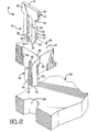
- the board lock or holding device 10 of the present invention is designed for holding an electrical connector 40 to a circuit board 60.
- Connector 40 includes a housing 42 having a mating face 44, a mounting face 46 and a device holding passageway 48 extending from a surface 47 opposed to the mounting face 46 and into a mounting post 50 extending from the mounting face 46 of housing 42.
- the connector 40 shown in Figure 1 is a surface mounted connector using flexible film circuitry having circuit traces 43 at the leading film edges for interconnection to circuit pads 64 on circuit board 60.
- the mounting post on the illustrated connector includes a pair of semicylindrical legs 51 that are joined at 54 at least at the leading ends thereof and define slots 56 therebetween.
- the legs are joined along a tapered rib like section 54 which extends from the leading end 52 toward the mounting face 46 of housing 42 as can best be seen in Figure 2.
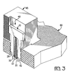
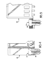
- the holding device 10 is shown in Figures 2, 3, and 5, in a flange 45 of a connector, in Figure 4 in the passageway 48 of a card edge connector 40 and in Figure 5 in the passageway 48 of a surface mountable top loaded connector 140. It is to be understood that the holding device 10 can be used in any style of connector or other component being mounting to a circuit board.
- the board lock or holding device 10 is a one-piece essentially planar metal member including a body 12 having opposed transverse edges 14 and end edges 16, and a pair of cantilevered beams 18 extending outwardly in a first direction in the plane from one of the transverse body edges 14 to free ends 24.
- the beams 18 have outer and inner edges 20,28, the inner edges 28 defining a slot 36 therebetween.
- the inner edges 28 of beams 18 further include inwardly directed projections 30 defining latching sections at the leading ends 24 thereof for lockingly engaging the transverse leading end or locking surface 57 of the board mounting post 50 when the board lock device 10 is fully inserted into the board holding device passageway 48, as best seen in Figures 3 and 4.
- body ends 15 of device 10 engage passageway stop surfaces 49.
- the inner beam edges 28 further have a lead-in surface 32 which slide along the tapered surfaces 53 of the rib like section 54 as the holding device 10 is inserted into passageway 48 thereby deflecting the beams 18 outwardly until the device 10 is fully seated in passageway 48, whereupon the projections or latching sections 30 engage the lower edge of rib section 54.
- Slot 36 is dimensioned to allow for compression of beams 18 during insertion into the board aperture 62 and to accommodate tolerance variations.
- the axial length of tapered rib section 54 is substantially equivalent to the axial length of slot 36 such that the innermost end 55 of rib 54 provides support along transverse edge 14 of device 10 intermediate the beams 18.
- the outer edges 20 of the beams 18 include a lead-in surface 22 at the free end 24 thereof and further include board locking barbs 26 extending outwardly from the outer edge.
- the width of the semicylindrical legs 51 is narrower than that of the width of the beams 18 of board holding device 10 such that the board engaging barbs 26 along the outer edges of beams 18 extend transversely outwardly of the slots 56 in the mounting post 50 and engage the sides of the retention aperture 62 of circuit board 60 when the connector 40 is mounted to the board 60.
- retention apertures 62 of board 60 may be plated thereby allowing the board locking devices 10 to be soldered in circuit board 60, by means known in the art.
- two of the holding devices 10 are used in the connector 40.
- the leading ends 52 of the mounting posts 50 align the connector 40 to assure that the terminals or other conductors within the connector are in alignment with the corresponding circuits pads 64 on the circuit board.
- the lead-in surfaces 22 along the outer edge of the board lock device 10 and the edges of the mounting post 50 guide and align the connector 40 into position.
- the tapered surfaces 27 of the barbs 26 aid in deflecting the beams 18 further inwardly thereby increasing the self-retaining force of the board lock device 10.
- the locking notches 32 of beams 18 are pushed into the leading end 52 of ribbed portion 54, thus preventing backward movement of the board lock device 10 during connector mounting. No tool, therefore, is needed to backup the end of the board lock device 10 to force it into engagement in the board.
- the device 10 has sufficient latching or self-retaining force to remain secured within passageway 48 when inserted into board apertures within the standard range associated with standard board sizes.
- the holding device 10 is stamped from a sheet of metal stock of sufficient thickness and hardness to serve as a holding device by virtue of the barbs 26 thereon engaging the interior surface 62 of the board apertures.
- Materials such as brass, phosphor bronze, or stainless steel may be employed with the thicknesses ranging on the order of about 0.008 to 0.025 inches.
- the axial length of the device 10 depends upon dimensions of the passageway 48 and thickness of the board apertures such that the body portion 12 of the device 10 is held within the passageway 48 and the beams 18 extend into the bifurcated passageway portion of the mounting post 50.
- Figure 6 shows a holding device 110 according to an alternative embodiment of the invention that is particularly suitable for thinner stock materials, in a passageway 148 of a connector flange 145.
- the leading ends of latching projections 130 are only minimally separated and extend along a greater portion of the leading end 157 of rib 154 of connector flange 145 than do the devices made of thicker stock, thereby providing essentially the same retention force as the device made from thicker stock.
- the connector assembly of the present invention is cost effective to manufacture, since the configuration of the board lock device and the housing passageway and post in which the device is loaded permit the connector housing to be molded in a single draw mold using suitable materials as known in the art. Furthermore, the ability to top load the board lock device as well as terminal members into a connector housing facilitates the use of automated processes.
Landscapes
- Coupling Device And Connection With Printed Circuit (AREA)
- Multi-Conductor Connections (AREA)
Applications Claiming Priority (2)
| Application Number | Priority Date | Filing Date | Title |
|---|---|---|---|
| US08/248,262 US5489219A (en) | 1994-05-24 | 1994-05-24 | Self-retaining board lock |
| US248262 | 1994-05-24 |
Publications (2)
| Publication Number | Publication Date |
|---|---|
| EP0684667A2 true EP0684667A2 (de) | 1995-11-29 |
| EP0684667A3 EP0684667A3 (de) | 1996-07-03 |
Family
ID=22938353
Family Applications (1)
| Application Number | Title | Priority Date | Filing Date |
|---|---|---|---|
| EP95302677A Ceased EP0684667A3 (de) | 1994-05-24 | 1995-04-21 | Selbsthalterungsriegel für eine Platte. |
Country Status (5)
| Country | Link |
|---|---|
| US (1) | US5489219A (de) |
| EP (1) | EP0684667A3 (de) |
| JP (1) | JPH0850970A (de) |
| KR (1) | KR100347241B1 (de) |
| BR (1) | BR9502479A (de) |
Families Citing this family (7)
| Publication number | Priority date | Publication date | Assignee | Title |
|---|---|---|---|---|
| US5755592A (en) * | 1996-09-27 | 1998-05-26 | The Whitaker Corporation | Combined ground strap and board lock for electrical connector assembly |
| TW323014U (en) * | 1997-06-07 | 1997-12-11 | Hon Hai Prec Ind Co Ltd | Electrical connector |
| US6000955A (en) | 1997-12-10 | 1999-12-14 | Gabriel Technologies, Inc. | Multiple terminal edge connector |
| US6123580A (en) * | 1998-04-30 | 2000-09-26 | The Whitaker Corporation | Board lock for an electrical connector |
| US6486406B1 (en) * | 2000-11-14 | 2002-11-26 | 3Com Corporation | Latching apparatus and method for providing radial alignment of a housing mounted on a circuit board |
| JP4833672B2 (ja) * | 2006-01-23 | 2011-12-07 | 株式会社東海理化電機製作所 | 固定部材、及び、取付構造 |
| JP4737544B2 (ja) * | 2006-07-26 | 2011-08-03 | 住友電装株式会社 | 基板用コネクタ |
Family Cites Families (54)
| Publication number | Priority date | Publication date | Assignee | Title |
|---|---|---|---|---|
| GB1128404A (en) * | 1966-04-07 | 1968-09-25 | Ml Aviation Co Ltd | Improvements relating to releasable fasteners |
| CH516233A (de) * | 1968-03-09 | 1971-11-30 | Hengstler Kg | Rastvorrichtung für ineinander steckbare Bauteile |
| US3577603A (en) * | 1968-10-02 | 1971-05-04 | United Carr Inc | Fastener |
| US3659243A (en) * | 1969-10-24 | 1972-04-25 | Amp Inc | Electrical connectors |
| US3778755A (en) * | 1972-11-06 | 1973-12-11 | Berg Electronics Inc | Self-staking wire grip terminal |
| US4186982A (en) * | 1973-08-01 | 1980-02-05 | Amp Incorporated | Contact with split portion for engagement with substrate |
| JPS5183793A (de) * | 1975-01-21 | 1976-07-22 | Japan Broadcasting Corp | |
| FR2386963A1 (fr) * | 1977-04-07 | 1978-11-03 | Cit Alcatel | Dispositif de fixation pour connecteur |
| US4457570A (en) * | 1980-02-12 | 1984-07-03 | Virginia Patent Development Corporation | Connector for mating modular plug with printed circuit board |
| DE7914042U1 (de) * | 1979-05-15 | 1979-08-16 | Siemens Ag, 1000 Berlin Und 8000 Muenchen | Vielfachsteckverbindung |
| GB2058485A (en) * | 1979-09-04 | 1981-04-08 | Bicc Burndy Ltd | Electrical terminals |
| US4461537A (en) * | 1981-12-24 | 1984-07-24 | Molex Incorporated | Fiber optic connector assembly |
| US4435031A (en) * | 1982-01-07 | 1984-03-06 | Holmberg Electronics Corporation | Connector block with snap latch |
| US4495548A (en) * | 1982-11-12 | 1985-01-22 | Kitagawa Industries Co., Ltd. | Spacer for wiring boards and assembled structure thereof |
| US4477142A (en) * | 1983-03-29 | 1984-10-16 | Amp Incorporated | Fastener |
| US4641901A (en) * | 1984-01-16 | 1987-02-10 | Stewart Stamping Corp. | Printed circuit board jack for modular plug connector terminated cord |
| BR8505361A (pt) * | 1984-10-29 | 1986-08-05 | Du Pont | Blindagem inteirica de conecto de painel de circuito impresso |
| US4618915A (en) * | 1984-12-17 | 1986-10-21 | Illinois Tool Works Inc. | Support member for electrical components |
| JPH035100Y2 (de) * | 1985-01-23 | 1991-02-08 | ||
| US4693532A (en) * | 1985-02-04 | 1987-09-15 | Molex Incorporated | Modular staggered multi-row electrical connector |
| US4645287A (en) * | 1985-09-09 | 1987-02-24 | Amp Incorporated | Surface mount connector |
| US4703991B1 (en) * | 1986-01-10 | 1997-05-13 | Stewart Connector Systems Inc | Low profile jack |
| US4735587A (en) * | 1986-02-12 | 1988-04-05 | Specialty Electronics, Inc. | Pin header with board retention tail |
| CA1282847C (en) * | 1986-03-05 | 1991-04-09 | Ray C. Doutrich | Electrical connector with pin retention feature |
| USD299004S (en) | 1986-03-13 | 1988-12-20 | Kitagawa Industries Co., Ltd. | Retainer for retaining boards |
| US4717219A (en) * | 1986-06-19 | 1988-01-05 | Amp Incorporated | Electrical connector and assembly eyelets |
| US4679883A (en) * | 1986-09-08 | 1987-07-14 | Amp Incorporated | Shoulder eyelet board lock |
| US4723059A (en) * | 1986-10-16 | 1988-02-02 | Teleflex Incorporated | Tachometer switch |
| DE3636065C1 (de) * | 1986-10-23 | 1988-04-28 | Klaus Lorenzen | Halterung von elektrischen Bauelementen auf einer Schaltungsplatte |
| US4721473A (en) * | 1986-11-17 | 1988-01-26 | Amp Incorporated | Retention feature for printed circuit board mounted connectors |
| US4865555A (en) * | 1987-08-03 | 1989-09-12 | Amp Incorporated | Connector with open-ended boardlock |
| US4824398A (en) * | 1987-08-21 | 1989-04-25 | Amp Incorporated | Solderable standoff boardlock |
| US4841100A (en) * | 1987-09-02 | 1989-06-20 | Minnesota Mining And Manufacturing Company | Expanding surface mount compatible retainer post |
| US4842552A (en) * | 1988-03-04 | 1989-06-27 | Amp Incorporated | Tolerance forgiving boardlock |
| US4820180A (en) * | 1988-06-09 | 1989-04-11 | Molex Incorporated | Floating panel mount for electrical connector |
| US4907987A (en) * | 1988-11-04 | 1990-03-13 | Amp Incorporated | Connector with barbed boardlock |
| US5115349A (en) * | 1989-05-25 | 1992-05-19 | Kabushiki Kaisha Machida Seisakusho | Projector system and system for detecting flaw |
| DE8907785U1 (de) * | 1989-06-26 | 1989-08-24 | Siemens AG, 1000 Berlin und 8000 München | Mit einer Leiterplatte verbindbare Koaxialsteckverbinderhälfte oder Hochstromkontakt |
| MY107281A (en) * | 1989-11-02 | 1995-10-31 | Whitaker Corp | Retaining device for electrical connectors. |
| JPH042282A (ja) * | 1990-04-19 | 1992-01-07 | Canon Inc | 撮像装置 |
| JP2791831B2 (ja) * | 1990-10-26 | 1998-08-27 | 日本エー・エム・ピー株式会社 | 電気コネクタ |
| US5080611A (en) * | 1990-12-21 | 1992-01-14 | Amp Incorporated | Boardlock for common-hole double-sided mounting |
| US5135412A (en) * | 1991-01-29 | 1992-08-04 | E. I. Du Pont De Nemours And Company | Hold-down terminal |
| JP2567344Y2 (ja) * | 1991-02-08 | 1998-04-02 | 日本エー・エム・ピー株式会社 | 表面実装型電気コネクタ |
| US5145407A (en) * | 1991-11-25 | 1992-09-08 | Amp Incorporated | Mounting device for components |
| US5154634A (en) * | 1991-12-12 | 1992-10-13 | Amp Incorporated | Connector holding device |
| WO1993018560A1 (en) * | 1992-03-13 | 1993-09-16 | Itt Industries, Inc. | Holdown key for low profile connector |
| US5161999A (en) * | 1992-03-18 | 1992-11-10 | Amp Incorporated | Surface mount electrical cohnnector and shield therefor |
| US5176349A (en) * | 1992-03-27 | 1993-01-05 | Amp Incorporated | Post retention arrangement |
| US5163851A (en) * | 1992-04-03 | 1992-11-17 | Amp Incorporated | Connector with formed wire boardlock and boardlock therefor |
| US5322452A (en) * | 1992-05-29 | 1994-06-21 | Itt Corporation | Holddown system for connector |
| US5228870A (en) * | 1992-07-30 | 1993-07-20 | Amp Incorporated | Connector to circuit board securing arrangement with holding device insertion depth compensator |
| US5238413A (en) * | 1992-10-22 | 1993-08-24 | The Whitaker Corporation | Electrical connector with board mount feature |
| US5316500A (en) * | 1993-01-11 | 1994-05-31 | Ohio Associated Enterprises, Inc. | Fastener for a printed circuit board mounted connector |
-
1994
- 1994-05-24 US US08/248,262 patent/US5489219A/en not_active Expired - Lifetime
-
1995
- 1995-04-21 EP EP95302677A patent/EP0684667A3/de not_active Ceased
- 1995-05-19 BR BR9502479A patent/BR9502479A/pt not_active IP Right Cessation
- 1995-05-24 JP JP7125343A patent/JPH0850970A/ja active Pending
- 1995-05-24 KR KR1019950012980A patent/KR100347241B1/ko not_active Expired - Fee Related
Also Published As
| Publication number | Publication date |
|---|---|
| KR100347241B1 (ko) | 2002-11-30 |
| EP0684667A3 (de) | 1996-07-03 |
| BR9502479A (pt) | 1995-12-26 |
| KR950034929A (ko) | 1995-12-28 |
| JPH0850970A (ja) | 1996-02-20 |
| US5489219A (en) | 1996-02-06 |
Similar Documents
| Publication | Publication Date | Title |
|---|---|---|
| US5393247A (en) | Component mounting device | |
| US5228870A (en) | Connector to circuit board securing arrangement with holding device insertion depth compensator | |
| US5154634A (en) | Connector holding device | |
| US5074807A (en) | Component holding device | |
| US5139446A (en) | Electrical connector assembly | |
| US5395250A (en) | Low profile board to board connector | |
| US6592382B2 (en) | Simplified board connector | |
| US5785536A (en) | Connector having press fit mating shrouds | |
| US5827089A (en) | Board lock for electrical connector | |
| US4984996A (en) | Printed circuit board edge connector | |
| US6997756B2 (en) | Connector terminal, a connector and a mounting method | |
| US5980299A (en) | Board-mountable module guide | |
| US5403195A (en) | Socket having an auxiliary electrical component mounted thereon | |
| US5575663A (en) | Electrical connector for mounting to an edge of a circuit board | |
| US4474418A (en) | Electrical connector assembly | |
| EP0068656A1 (de) | Elektrischer Anschlusskontakt mit Hohlraumausgleichmittel | |
| US5489219A (en) | Self-retaining board lock | |
| US4744771A (en) | Fixing structure of contact tails of electrical connector | |
| US6123580A (en) | Board lock for an electrical connector | |
| US5989064A (en) | Board lock | |
| US4610496A (en) | Connector mechanical interlock using ball detents | |
| US5836792A (en) | Board mountable electrical connector | |
| US5443401A (en) | Electrical connector for mother and daughter printed circuit boards | |
| US6796835B2 (en) | Electrical connector with board lock | |
| US5803765A (en) | Electrical connector with universal boardlock |
Legal Events
| Date | Code | Title | Description |
|---|---|---|---|
| PUAI | Public reference made under article 153(3) epc to a published international application that has entered the european phase |
Free format text: ORIGINAL CODE: 0009012 |
|
| AK | Designated contracting states |
Kind code of ref document: A2 Designated state(s): DE FR GB IT NL |
|
| PUAL | Search report despatched |
Free format text: ORIGINAL CODE: 0009013 |
|
| AK | Designated contracting states |
Kind code of ref document: A3 Designated state(s): DE FR GB IT NL |
|
| 17P | Request for examination filed |
Effective date: 19961122 |
|
| GRAG | Despatch of communication of intention to grant |
Free format text: ORIGINAL CODE: EPIDOS AGRA |
|
| 17Q | First examination report despatched |
Effective date: 19990324 |
|
| STAA | Information on the status of an ep patent application or granted ep patent |
Free format text: STATUS: THE APPLICATION HAS BEEN REFUSED |
|
| 18R | Application refused |
Effective date: 19990918 |