EP0683348A2 - Device for sealing the wall of a pipe at the junction between a main and a lateral pipe - Google Patents
Device for sealing the wall of a pipe at the junction between a main and a lateral pipe Download PDFInfo
- Publication number
- EP0683348A2 EP0683348A2 EP95107387A EP95107387A EP0683348A2 EP 0683348 A2 EP0683348 A2 EP 0683348A2 EP 95107387 A EP95107387 A EP 95107387A EP 95107387 A EP95107387 A EP 95107387A EP 0683348 A2 EP0683348 A2 EP 0683348A2
- Authority
- EP
- European Patent Office
- Prior art keywords
- expansion body
- shield
- channel
- wall
- duct
- Prior art date
- Legal status (The legal status is an assumption and is not a legal conclusion. Google has not performed a legal analysis and makes no representation as to the accuracy of the status listed.)
- Withdrawn
Links
Images

Classifications
-
- F—MECHANICAL ENGINEERING; LIGHTING; HEATING; WEAPONS; BLASTING
- F16—ENGINEERING ELEMENTS AND UNITS; GENERAL MEASURES FOR PRODUCING AND MAINTAINING EFFECTIVE FUNCTIONING OF MACHINES OR INSTALLATIONS; THERMAL INSULATION IN GENERAL
- F16L—PIPES; JOINTS OR FITTINGS FOR PIPES; SUPPORTS FOR PIPES, CABLES OR PROTECTIVE TUBING; MEANS FOR THERMAL INSULATION IN GENERAL
- F16L55/00—Devices or appurtenances for use in, or in connection with, pipes or pipe systems
- F16L55/26—Pigs or moles, i.e. devices movable in a pipe or conduit with or without self-contained propulsion means
- F16L55/265—Pigs or moles, i.e. devices movable in a pipe or conduit with or without self-contained propulsion means specially adapted for work at or near a junction between a main and a lateral pipe
-
- F—MECHANICAL ENGINEERING; LIGHTING; HEATING; WEAPONS; BLASTING
- F16—ENGINEERING ELEMENTS AND UNITS; GENERAL MEASURES FOR PRODUCING AND MAINTAINING EFFECTIVE FUNCTIONING OF MACHINES OR INSTALLATIONS; THERMAL INSULATION IN GENERAL
- F16L—PIPES; JOINTS OR FITTINGS FOR PIPES; SUPPORTS FOR PIPES, CABLES OR PROTECTIVE TUBING; MEANS FOR THERMAL INSULATION IN GENERAL
- F16L55/00—Devices or appurtenances for use in, or in connection with, pipes or pipe systems
- F16L55/16—Devices for covering leaks in pipes or hoses, e.g. hose-menders
- F16L55/179—Devices for covering leaks in pipes or hoses, e.g. hose-menders specially adapted for bends, branch units, branching pipes or the like
Definitions
- the invention relates to a device for sealing duct walls in the region of the connection of a secondary duct to a main duct, with a carrying and positioning device which can be moved and fixed in the main duct for a shield which can be applied to the wall of the main duct in the region of the secondary duct connection and which can be adapted to the wall curvature an inflatable expandable body which can be introduced into the secondary duct, which in the inflated state rests against the wall of the secondary duct and then forms a formwork together with the shield, such that in the space between this formwork and the adjacent walls of the main and secondary duct a sealing compound can be pressed in, which forms duct wall regions which are sealed after the expansion body has been removed from the secondary duct and the shield has been removed from the duct connection region.
- the expansion body is a tubular balloon in the uninflated state, which protrudes from the shield in the direction of the inner wall of the main line.
- a formwork is pushed over this stretchable cylinder body, the cylinder body together with the pushed-on formwork is introduced into the secondary duct by moving the shield in a radial direction to the main duct and then the balloon is pressurized.
- the formwork is expanded and pressed against the inner wall of the secondary line.
- the space between the formwork, the shield and the damaged pipe walls is then filled with a sealing compound.
- this device makes it possible to remotely seal sewer connection areas without the secondary duct, as in other renovation methods, having to be drilled out or milled out after the sealing compound has been introduced.
- the expansion body in the non-inflated state protrudes radially from the shield even in its full length, which is essentially maintained even after it has been introduced into the secondary channel. This can lead to problems when moving the shield along the main line and when positioning it in relation to the junction of the secondary channel in the main channel.
- the maximum length of the tubular balloon is limited by the diameter of the main channel, so that the maximum depth of penetration into the secondary channel and thus the maximum possible machining depth in the secondary channel is limited, starting from the junction.
- the known device presupposes secondary channels branching perpendicularly and axially to the main channel. It is hardly suitable for secondary channels branching off at a noticeably different angle from 90 degrees, since the cylinder body with the formwork pushed on would then no longer be able to be moved into the secondary channel, at least not in such a way that the formwork was flush with the entire circumference of the main channel directly adjacent wall area of the secondary duct covers. Furthermore, the known device requires the use of an additional formwork component pushed onto the cylinder body. Use without formwork components is not intended. Problems with pulling out the cylinder body from the secondary duct would then also have to be expected. The adaptation of the device to different nominal duct sizes is possible at best by complex retrofitting of components.
- a remotely controllable device for repairing channel outlets is also shown in German Offenlegungsschrift DE 42 13 898.
- This device is also equipped with an expansion body which, with its entire length, which is essentially retained even after inflation, is moved radially to the main channel, because the inflatable jacket of the Expansion body surrounds a rigid cylindrical support body.
- This device therefore also has the disadvantages mentioned above.
- European published patent application EP 114 727 A1 discloses a sewer rehabilitation method developed in the USA and known as the LSS system (Lateral Sealing System), in which a packer with two inflatable packer sleeves, which are connected to one another by an intermediate piece, enters the main duct is introduced. From the intermediate part, a hose with compressed air can be inserted into the connecting channels. Injection medium pressed in between the pipe wall and hose seals the channel. Sealing compound also gets into the annular space between the intermediate part and the wall of the main channel. In practical use, it has been found that the packer can only be removed with great difficulty in the case of large quantities of sealing material to be pressed, in particular strongly hardening material.
- LSS system Lateral Sealing System
- the intermediate part for the angular positioning of the hose relative to the junction of the secondary channel is rotatably driven between the end sleeves, and a device for unwinding or winding up the hose is also accommodated in the intermediate part, the entire device is extremely expensive to construct. Like the devices previously recognized in the prior art, it is tied to nominal nominal channel widths of relatively narrow diameter ranges and can therefore only be used with little flexibility without expensive retrofitting.
- the invention has for its object to avoid the disadvantages mentioned above in the prior art, ie to provide a device for sealing channel walls in the area of the connection of a secondary channel to a main channel, which with little design effort in one Large duct nominal diameter range can be used without retrofitting, is easy to position and can be easily removed from the connection area after sealing.
- the device should also be equally suitable for secondary duct connections which run at an acute angle and / or with a curved pipe axis and / or which are not centered on the main duct.
- a device having the features of patent claim 1 that is to say in that, in a device of the generic type, the expansion body is formed exclusively from a layer of elastic material, that the expansion body in the weakly inflated state initially has the shape of a starting from the shield, at the tip is rounded hollow cone, which with increasing inflation changes into a cylindrical shape corresponding to the diameter of the secondary channel and its angle to the main channel, the expansion body increasingly growing into the secondary channel, and that the expansion body can be removed from the secondary channel by reducing the pressure acting on it .
- the subclaims relate to advantageous refinements of the device according to the invention.
- the device corresponding to the invention thus uses an expansion body that has no support body and solely because of its elasticity and its calculated layer thicknesses after the positioning of the shield on the wall of the main channel during inflation automatically and absolutely reliably both in the radial and in the axial direction in the secondary channel grows into it and lies closely against the walls of a secondary duct branching off at any angle, even if the secondary duct is not curved or kinked axially to the main duct or directly behind the connection area.
- the mode of operation of the device is unchanged in the case of secondary ducts of different nominal widths over a large nominal diameter range.
- a certain expansion body can be used in a range from nominal width 100 to nominal width 200 of the secondary duct. Nominal diameter changes with a factor of 2 can therefore still be handled with one and the same expansion body. Conversions to adapt to channel diameters that deviate greatly from the normal channel diameter range therefore only have to be carried out in rare cases, but are then possible without any problems, since the expansion body, which is formed simply from an elastic material layer, can be replaced - and possibly to adapt to the diameter of the main channel also of the shield - requires little assembly effort.
- the expansion body can be relieved of pressure after a very short time, in which case it collapses and can be brought out of the secondary duct without impairing the wall which has just been repaired in any way. Detachment of the expansion body surface by pressure reduction is so gently possible that even not yet fully hardened sealing compound remains intact in the freshly repaired duct wall. Formwork removal of the renovated sewer area is therefore possible very early. In addition, it can be done even faster if a thin, lost separating layer, in particular a plastic film, is applied to the area of the shield facing the wall of the main duct, which remains in the refurbished duct.
- the sealing compound can be conveyed under pressure, in particular via pipes or hoses, and is introduced into the compression gap via several mouthpieces at the base of the expansion body, that is to say in the region of its connection to the shield. It is distributed in particular around the base of the expansion body.
- expansion bodies with a particularly large linear expansion capability from the shield can be used, in the surface of which adjoins the foot, one or more outlet openings for the sealing compound are formed. These outlet openings are connected to movable feed lines which, when the expansion body grows into the secondary channel, track the surface of the expansion body and follow the moving outlet opening.
- the sealant can also be applied in sufficient quantity and under sufficient pressure to damaged areas deeper in the secondary duct.
- the initial layer thickness of the elastic material layer of the expansion body is calculated as a function of its surface extension so that when it inflates, the spatial shape of a hollow cone rounded off at the top is obtained, and that as the inflation increases, there is a progression from the base of the cone, i.e. the shield adapted to the secondary channel, following the conical tip of the cylinder trains.
- This makes it possible for the expansion body to grow into the secondary channel to a sufficient depth with minimized friction on the walls of the secondary channel and, with the opposite shape change behavior, to be separated from the repaired wall after the pressure relief and to be removed from the secondary channel.
- the application can be carried out by means of negative pressure, so that the expansion body can be sucked in behind the contact surface of the sign and then in particular can be completely sunk into a flat box on the sign.
- This position can also be the starting position from which the expansion body is introduced into the secondary channel by being inflated, so that the expansion body does not protrude from the shield at all when the carrying and positioning device is moved in the main channel.
- the layer thickness of the expansion body is otherwise optimized so that its cylindrical shape is largely retained when inserted into the secondary channel, even if parts of the secondary channel wall are missing.
- the wall thickness of the expansion body is calculated in such a way that it can maintain its cylindrical shape corresponding to the nominal size of the secondary channel by controlling the internal pressure of the expansion body and the delivery pressure of the sealing compound, in particular also in the area of the defective wall parts.
- the damaged canal wall is therefore restored very precisely, or missing canal walls are newly formed to fit, so that in most cases a subsequent material-removing canal wall treatment is no longer required in the renovation practice.
- the very special advantage of the device according to the invention lies in the fact that, in contrast to the devices acknowledged at the beginning of the prior art, it is suitable for repairing from any angle to the main channel, also outside its center axis or curved secondary channels. Even if the secondary channel forms an acute angle with the main channel, the expansion body easily grows from the shield into the secondary channel due to its great adaptability when inflated. After sealing, it can then also be removed from the secondary duct just as easily by relieving pressure or applying negative pressure.
- the positioning of the shield in the region of the duct connection is also simplified with the device according to the invention, because the expansion body can be inserted into the secondary duct by inflation when its rounded hollow cone tip is located somewhere within the mouth of the secondary duct.
- the high adaptability of the expansion body to the surrounding channel walls compensates for any positioning inaccuracies. The positioning therefore does not require much effort and is quick and easy to carry out.
- the shield of the device can be formed over a large area and be provided with appropriate outlet openings for sealing compound that the star-shaped crack formation in the main channel, which frequently occurs in practice, is sealed in one operation together with the repair of the secondary channel.
- the shield is able to adapt to the wall curvature within a certain nominal diameter range of the main duct, so that at least the diameter variations that occur frequently in practice are covered, which can vary due to the tolerances permitted by DIN, e.g. B. with different materials.
- DIN e.g. B.
- it can have a rubber-like pad.
- it can be designed as a structure with lamellae which run in the longitudinal direction of the main channel and are bendable relative to one another.
- inflation of the expansion body should generally be understood to mean its expansion by applying internal pressure. This can be done using a gas, especially air. However, it is also conceivable to expand the expansion body by pumping in a liquid.
- the carrying and positioning device of the device according to the invention can, as explained below with reference to the drawing, be formed in different ways.
- the carrying and positioning device is a remote-controllable sewer rehabilitation robot.
- the shield 1 On its head, which can be moved in three degrees of freedom, the shield 1 is fastened, which can be positioned by means of the externally controllable head drive together with the expansion body 2 in the connection region of the secondary duct 3 to the main duct 4.
- FIG. 2 shows that the carrying and positioning device can also comprise a tensioning device 6, which is supported against the wall area of the main channel 4 radially opposite the plate 1 and presses the plate 1 in the channel connection area.
- a tensioning device 6 which is supported against the wall area of the main channel 4 radially opposite the plate 1 and presses the plate 1 in the channel connection area.
- Figure 3 shows a schematic representation that the carrying and positioning device can also be a carriage 7, on which the shield 1 with the expansion body 2 is rotatably mounted about an axis of rotation parallel to the axis of the main channel 4.
- the shield 1 can be positioned particularly reliably in the circumferential direction of the main channel 4.
- the carriage 7 has means for pressing the shield 1 against the wall of the main channel 4.
Landscapes
- Engineering & Computer Science (AREA)
- General Engineering & Computer Science (AREA)
- Mechanical Engineering (AREA)
- Chemical & Material Sciences (AREA)
- Combustion & Propulsion (AREA)
- Pipe Accessories (AREA)
Abstract
Description
Die Erfindung betrifft eine Vorrichtung zum Abdichten von Kanalwandungen im Bereich des Anschlusses eines Nebenkanals an einen Hauptkanal, mit einer im Hauptkanal verfahr- und festlegbaren Trage- und Positioniervorrichtung für einen im Bereich des Nebenkanalanschlusses an die Wandung des Hauptkanals anlegbaren, der Wandungskrümmung anpaßbaren Schild, der einen in den Nebenkanal einbringbaren, aufblasbaren Dehnkörper trägt, der im aufgeblasenen Zustand gegen die Wandung des Nebenkanals anliegt und dann zusammen mit dem Schild eine Schalung bildet, derart, daß in den Raum zwischen dieser Schalung und den ihr benachbarten Wandungen des Haupt- und des Nebenkanals eine Dichtmasse einpreßbar ist, die nach dem Ausbringen des Dehnkörpers aus dem Nebenkanal und dem Entfernen des Schildes aus dem Kanalanschlußbereich abgedichtete Kanalwandbereiche bildet.The invention relates to a device for sealing duct walls in the region of the connection of a secondary duct to a main duct, with a carrying and positioning device which can be moved and fixed in the main duct for a shield which can be applied to the wall of the main duct in the region of the secondary duct connection and which can be adapted to the wall curvature an inflatable expandable body which can be introduced into the secondary duct, which in the inflated state rests against the wall of the secondary duct and then forms a formwork together with the shield, such that in the space between this formwork and the adjacent walls of the main and secondary duct a sealing compound can be pressed in, which forms duct wall regions which are sealed after the expansion body has been removed from the secondary duct and the shield has been removed from the duct connection region.
Eine solche Vorrichtung ist aus der europäischen Patentschrift EP 455 764 B1 bekannt. Bei dieser ist der Dehnkörper ein in unaufgeblasenem Zustand rohrförmiger Ballon, der aus dem Schild in Richtung der Innenwand der Hauptleitung herausragt. Zum Ausbessern eines schadhaften Kanalanschlußbereichs wird über diesen dehnbaren Zylinderkörper eine Schalung geschoben, der Zylinderkörper zusammen mit der aufgeschobenen Schalung durch Verfahren des Schildes in zum Hauptkanal radialer Richtung in den Nebenkanal eingebracht und anschließend der Ballon mit Druck beaufschlagt. Dabei wird die Schalung aufgeweitet und an die Innenwand der Nebenleitung angepreßt. Der Raum zwischen der Schalung, dem Schild und den beschädigten Rohrwandungen wird anschließend mit einer Dichtungsmasse ausgefüllt.Such a device is known from the European patent EP 455 764 B1. In this case, the expansion body is a tubular balloon in the uninflated state, which protrudes from the shield in the direction of the inner wall of the main line. To repair a defective duct connection area, a formwork is pushed over this stretchable cylinder body, the cylinder body together with the pushed-on formwork is introduced into the secondary duct by moving the shield in a radial direction to the main duct and then the balloon is pressurized. The formwork is expanded and pressed against the inner wall of the secondary line. The space between the formwork, the shield and the damaged pipe walls is then filled with a sealing compound.
Diese Vorrichtung ermöglicht zwar, Kanalanschlußbereiche ferngesteuert abzudichten, ohne daß der Nebenkanal, wie bei anderen Sanierungsverfahren, im Anschluß an das Einbringen der Dichtungsmasse aufgebohrt oder ausgefräst werden muß. Sie ist aber dadurch nachteilig, daß der Deh nkörper i m nicht aufgeblasenen Zustand bereits in voller, im wesentlichen auch nach dem Einbringen in den Nebenkanal erfolgender Druckbeaufschlagung beibehaltener Länge radial von dem Schild absteht. Dies kann zu Problemen beim Verfahren des Schildes entlang der Hauptleitung und bei seiner Positionierung gegenüber der Einmündung des Nebenkanals in den Hauptkanal führen. Die maximale Längenausdehnung des rohrförmigen Ballons findet durch den Durchmesser des Hauptkanals vorgegebene Grenzen, so daß auch die maximale Eindringtiefe in den Nebenkanal und damit die maximal mögliche Bearbeitungstiefe im Nebenkanal, ausgehend von der Einmündungsstelle, begrenzt ist. Weiterhin setzt die bekannte Vorrichtung senkrecht und achsmittig zum Hauptkanal abzweigende Nebenkanäle voraus. Für in einem von 90 Grad merklich verschiedenen Winkel abzweigende Nebenkanäle ist sie kaum geeignet, da sich der Zyl inderkörper mit der aufgeschobenen Schalung dann nicht mehr in den Nebenkanal einfahren ließe, jedenfalls nicht so, daß die Schalung wandbündig den gesamten Umfang des an den Hauptkanal unmittelbar angrenzenden Wandbereichs des Nebenkanals abdeckt. Ferner erfordert die bekannte Vorrichtung den Einsatz eines zusätzlichen, auf den Zylinderkörper aufgeschobenen Schalungsbauteils. Ein Einsatz ohne Schalungsbauteil ist nicht beabsichtigt. Es müßte dann auch mit Problemen beim Herausziehen des Zylinderkörpers aus dem Nebenkanal gerechnet werden. Die Anpassung der Vorrichtung an unterschiedliche Kanalnennweiten ist allenfalls durch aufwendiges Umrüsten von Bauteilen möglich.Although this device makes it possible to remotely seal sewer connection areas without the secondary duct, as in other renovation methods, having to be drilled out or milled out after the sealing compound has been introduced. However, it is disadvantageous in that the expansion body in the non-inflated state protrudes radially from the shield even in its full length, which is essentially maintained even after it has been introduced into the secondary channel. This can lead to problems when moving the shield along the main line and when positioning it in relation to the junction of the secondary channel in the main channel. The maximum length of the tubular balloon is limited by the diameter of the main channel, so that the maximum depth of penetration into the secondary channel and thus the maximum possible machining depth in the secondary channel is limited, starting from the junction. Furthermore, the known device presupposes secondary channels branching perpendicularly and axially to the main channel. It is hardly suitable for secondary channels branching off at a noticeably different angle from 90 degrees, since the cylinder body with the formwork pushed on would then no longer be able to be moved into the secondary channel, at least not in such a way that the formwork was flush with the entire circumference of the main channel directly adjacent wall area of the secondary duct covers. Furthermore, the known device requires the use of an additional formwork component pushed onto the cylinder body. Use without formwork components is not intended. Problems with pulling out the cylinder body from the secondary duct would then also have to be expected. The adaptation of the device to different nominal duct sizes is possible at best by complex retrofitting of components.
Eine fernsteuerbare Vorrichtung zum Reparieren von Kanaleinmündungen zeigt auch die deutsche Offenlegungsschrift DE 42 13 898. Auch diese Vorrichtung ist mit einem Dehnkörper ausgestattet, der mit seiner ganzen, im wesentlichen auch nach dem Aufblasen beibehaltenen Länge radial zum Hauptkanal verfahren wird, denn der aufblasbare Mantel des Dehnkörpers umgibt einen steifen zylindrischen Stützkörper. Diese Vorrichtung weist daher ebenfalls die zuvor erwähnten Nachteile auf.A remotely controllable device for repairing channel outlets is also shown in German Offenlegungsschrift DE 42 13 898. This device is also equipped with an expansion body which, with its entire length, which is essentially retained even after inflation, is moved radially to the main channel, because the inflatable jacket of the Expansion body surrounds a rigid cylindrical support body. This device therefore also has the disadvantages mentioned above.
Schließlich ist mit der europäischen Offenlegungsschrift EP 114 727 A1 ein in den USAentwickeltes, unter der Bezeichnung LSS-System - Lateral Sealing System - bekanntgewordenes Kanalsanierungsverfahren offenbart, bei dem ein Packer mit zwei aufblasbaren Packermanschetten, die durch ein Zwischenstück miteinander verbunden sind, in den Hauptkanal eingebracht wird. Aus dem Zwischenteil kann seitlich ein Schlauch mit Druckluft in Anschlußkanäle eingefahren werden. Zwischen Rohrwandung und Schlauch eingepreßtes Injektionsmittel dichtet den Kanal ab. Abdichtmasse gelangt auch in den Ringraum zwischen dem Zwischenteil und der Wandung des Hauptkanals. Im praktischen Einsatz hat sich erwiesen, daß der Packer bei großen Mengen zu verpressenden, insbesondere stark verfestigenden Dichtmaterials nur unter großen Schwierigkeiten entfernt werden kann.Finally, European published patent application EP 114 727 A1 discloses a sewer rehabilitation method developed in the USA and known as the LSS system (Lateral Sealing System), in which a packer with two inflatable packer sleeves, which are connected to one another by an intermediate piece, enters the main duct is introduced. From the intermediate part, a hose with compressed air can be inserted into the connecting channels. Injection medium pressed in between the pipe wall and hose seals the channel. Sealing compound also gets into the annular space between the intermediate part and the wall of the main channel. In practical use, it has been found that the packer can only be removed with great difficulty in the case of large quantities of sealing material to be pressed, in particular strongly hardening material.
Da das Zwischenteil zur Winkelpositionierung des Schlauches gegenüber der Einmündung des Nebenkanals drehantreibbar zwischen den Endmanschetten gelagert ist, ferner auch eine Einrichtung zum Ab- bzw. Aufwickeln des Schlauches im Zwischenteil aufgenommen ist, ist die gesamte Vorrichtung außerordentlich konstruktionsaufwendig. Ebenso wie die zuvor zum Stand der Technik gewürdigten Vorrichtungen ist sie an Kanalnennweiten vorgegebener, relativ enger Durchmesserbereiche gebunden und daher ohne aufwendige Umrüstungen nur wenig flexibel einsetzbar.Since the intermediate part for the angular positioning of the hose relative to the junction of the secondary channel is rotatably driven between the end sleeves, and a device for unwinding or winding up the hose is also accommodated in the intermediate part, the entire device is extremely expensive to construct. Like the devices previously recognized in the prior art, it is tied to nominal nominal channel widths of relatively narrow diameter ranges and can therefore only be used with little flexibility without expensive retrofitting.
Demgegenüber liegt der Erfindung die Aufgabe zugrunde, die zuvor beim Stand der Technik genannten Nachteile zu vermeiden, d. h. eine Vorrichtung zum Abdichten von Kanalwandungen im Bereich des Anschlusses eines Nebenkanals an einen Hauptkanal anzugeben, die bei geringem konstruktiven Aufwand in einem großen Kanal-Nennweitenbereich ohne Umrüstungen verwendbar, leicht zu positionieren und problemlos nach dem Abdichten aus dem Anschlußbereich zu entfernen ist. Darüber hinaus soll die Vorrichtung ebenso wie für senkrecht abzweigende auch für unter einem spitzen Winkel und/oder mit gekrümmter Rohrachse und/oder nicht achsmittig zum Hauptkanal verlaufende Nebenkanalanschlüsse in gleicherweise geeignet sein. Schließlich sollen auch Schäden im Nebenkanal abdichtbar sein, die in einer über den Durchmesser des Hauptkanals hinausgehenden Tiefe vorliegen.In contrast, the invention has for its object to avoid the disadvantages mentioned above in the prior art, ie to provide a device for sealing channel walls in the area of the connection of a secondary channel to a main channel, which with little design effort in one Large duct nominal diameter range can be used without retrofitting, is easy to position and can be easily removed from the connection area after sealing. In addition, as well as for vertically branching, the device should also be equally suitable for secondary duct connections which run at an acute angle and / or with a curved pipe axis and / or which are not centered on the main duct. Finally, it should also be possible to seal damage in the secondary duct that is present at a depth that goes beyond the diameter of the main duct.
Die Lösung dieser Aufgabe erfolgt durch eine Vorrichtung mit den Merkmalen des Patentanspruchs 1, also dadurch, daß bei einer gattungsgemäßen Vorrichtung der Dehnkörper ausschließlich aus einer Schicht elastischen Materials gebildet ist, daß der Dehnkörper in schwach aufgeblasenem Zustand zunächst die Form eines von dem Schild ausgehenden, an der Spitze abgerundeten Hohlkegels einnimmt, die bei zunehmendem Aufblasen in eine dem Durchmesser des Nebenkanals und seiner Abwinkelung zum Hauptkanal entsprechende Zylinderform übergeht, wobei der Dehnkörper zunehmend in den Nebenkanal hineinwächst, und daß der Dehnkörper durch Verminderung des ihn beaufschlagenden Druckes aus dem Nebenkanal ausbringbar ist.This object is achieved by a device having the features of patent claim 1, that is to say in that, in a device of the generic type, the expansion body is formed exclusively from a layer of elastic material, that the expansion body in the weakly inflated state initially has the shape of a starting from the shield, at the tip is rounded hollow cone, which with increasing inflation changes into a cylindrical shape corresponding to the diameter of the secondary channel and its angle to the main channel, the expansion body increasingly growing into the secondary channel, and that the expansion body can be removed from the secondary channel by reducing the pressure acting on it .
Die Unteransprüche betreffen vorteilhafte Ausgestaltungen der erfindungsgemäßen Vorrichtung.The subclaims relate to advantageous refinements of the device according to the invention.
Die der Erfindung entsprechende Vorrichtung verwendet also einen Dehnkörper, der keinerlei Stützkörper aufweist und allein aufgrund seiner Elastizität und seiner berechneten Schichtdicken nach der Positionierung des Schildes an der Wandung des Hauptkanals beim Aufblasen selbsttätig und absolut zuverlässig sowohl in radialer als auch in axialer Richtung in den Nebenkanal hineinwächst und sich dabei eng an die Wandungen eines unter einem beliebigen Winkel abzweigenden Nebenkanals anlegt, und zwar auch dann, wenn der Nebenkanal nicht achsmittig zum Hauptkanal oder direkt hinter dem Anschlußbereich gekrümmt oder abgeknickt verläuft.The device corresponding to the invention thus uses an expansion body that has no support body and solely because of its elasticity and its calculated layer thicknesses after the positioning of the shield on the wall of the main channel during inflation automatically and absolutely reliably both in the radial and in the axial direction in the secondary channel grows into it and lies closely against the walls of a secondary duct branching off at any angle, even if the secondary duct is not curved or kinked axially to the main duct or directly behind the connection area.
Letzteres ist ein wesentlicher Vorteil der erfindungsgemäßen Vorrichtung gegenüber den eingangs zum Stand der Technik abgehandelten Abdichteinrichtungen, denn bei Sanierungsarbeiten in der Praxis ist damit zu rechnen, daß etwa 9 von 10 Nebenkanälen anders als achsmittig und geradlinig unter einem Winkel von 90 Grad zum Hauptkanal abzweigen.The latter is a significant advantage of the device according to the invention compared to the sealing devices initially dealt with in the prior art, because during renovation work in practice it is to be expected that about 9 out of 10 secondary ducts will branch off at an angle of 90 degrees to the main duct other than in the middle and straight.
Die Wirkungsweise der Vorrichtung ist dabei bei Nebenkanälen unterschiedlicher Nennweiten über einen großen Nennweitenbereich unverändert gleich. Das heißt, mit ein und demselben Dehnkörper können Nebenkanäle ganz unterschiedlicher Durchmeser ausgebessert werden. Beispielsweise kann ein bestimmter Dehnkörper in einem Bereich von Nennweite 100 bis Nennweite 200 des Nebenkanals eingesetzt werden. Nennweitenänderungen mit Faktor 2 können also noch mit ein und demselben Dehnkörper bewältigt werden. Umrüstungen zurAnpassung an von dem normalen Kanaldurchmesserbereich stark abweichende Kanaldurchmesser müssen daher nur noch in seltenen Fällen vorgenommen werden, sind dann aber problemlos möglich, da das Auswechseln des überaus einfach aus lediglich einer elastischen Materialschicht gebildeten Dehnkörpers - und ggf. zur Anpassung an den Durchmesser des Hauptkanals auch des Schildes - nur einen geringen Montageaufwand erfordert.The mode of operation of the device is unchanged in the case of secondary ducts of different nominal widths over a large nominal diameter range. This means that with one and the same expansion body, secondary channels of very different diameters can be repaired. For example, a certain expansion body can be used in a range from nominal width 100 to nominal width 200 of the secondary duct. Nominal diameter changes with a factor of 2 can therefore still be handled with one and the same expansion body. Conversions to adapt to channel diameters that deviate greatly from the normal channel diameter range therefore only have to be carried out in rare cases, but are then possible without any problems, since the expansion body, which is formed simply from an elastic material layer, can be replaced - and possibly to adapt to the diameter of the main channel also of the shield - requires little assembly effort.
Nach dem Einpressen der Dichtmasse kann der Dehnkörper schon nach sehr kurzer Zeit druckentlastet werden, wobei er kollabiert und ohne die gerade ausgebesserte Wandung in irgendeiner Weise zu beeinträchtigen aus dem Nebenkanal ausbringbar ist. Das Ablösen der Dehnkörperoberfläche durch Druckabbau ist so schonend möglich, daß auch noch nicht vollständig ausgehärtete Dichtmasse unversehrt in der frisch ausgebesserten Kanalwandung verbleibt. Das Ausschalen des sanierten Kanalbereichs ist also sehrfrühzeitig möglich. Es kann überdies noch schneller erfolgen, wenn auf den der Wandung des Hauptkanals zugewandten Bereich des Schildes eine dünne, verlorene Trennschicht, insbesondere eine Kunststoffolie aufgebracht wird, die im sanierten Kanal verbleibt.After the sealing compound has been pressed in, the expansion body can be relieved of pressure after a very short time, in which case it collapses and can be brought out of the secondary duct without impairing the wall which has just been repaired in any way. Detachment of the expansion body surface by pressure reduction is so gently possible that even not yet fully hardened sealing compound remains intact in the freshly repaired duct wall. Formwork removal of the renovated sewer area is therefore possible very early. In addition, it can be done even faster if a thin, lost separating layer, in particular a plastic film, is applied to the area of the shield facing the wall of the main duct, which remains in the refurbished duct.
Die Dichtmasse kann insbesondere über Rohre oder Schläuche unter Druck herangefördert werden und wird über mehrere Mundstücke am Fuß des Dehnkörpers, das heißt im Bereich seiner Anbindung an den Schild, in den Verpreßspalt eingebracht. Sie verteilt sich dabei insbesondere am Fuß des Dehnkörpers um diesen herum.The sealing compound can be conveyed under pressure, in particular via pipes or hoses, and is introduced into the compression gap via several mouthpieces at the base of the expansion body, that is to say in the region of its connection to the shield. It is distributed in particular around the base of the expansion body.
Für Sonderfälle von tiefer in den Nebenkanal hineinragenden Wandungsschäden können Dehnkörper mit einer besonders großen linearen Ausdehnungsfähigkeit vom Schild aus verwendet werden, in deren an den Fuß anschließender Oberfläche eine oder mehrere Austrittsöffnungen für die Dichtmasse ausgebildet sind. Diese Austrittsöffnungen stehen mit bewegbaren Zuführleitungen in Verbindung, die beim Hineinwachsen des Dehnkörpers in den Nebenkanal der Oberfläche des Dehnkörpers nachgeführt werden und der sich fortbewegenden Austrittsöffnung folgen. Die Dichtmasse kann so auch an tiefer im Nebenkanal liegende Schadstellen in ausreichender Menge und unter ausreichendem Druck herangebracht werden.For special cases of wall damage projecting deeper into the secondary duct, expansion bodies with a particularly large linear expansion capability from the shield can be used, in the surface of which adjoins the foot, one or more outlet openings for the sealing compound are formed. These outlet openings are connected to movable feed lines which, when the expansion body grows into the secondary channel, track the surface of the expansion body and follow the moving outlet opening. The sealant can also be applied in sufficient quantity and under sufficient pressure to damaged areas deeper in the secondary duct.
Die anfängliche Schichtdicke der elastischen Materialschicht des Dehnkörpers ist in Abhängigkeit von seiner Oberflächenerstreckung so berechnet, daß sich beim Aufblasen zunächst die Raumform eines an der Spitze abgerundeten Hohlkegels ergibt, und daß sich bei zunehmendem Aufblasen eine von der Kegelbasis, also dem Schild ausgehende, dem Verlauf des Nebenkanals angepaßte, der Kegelspitze folgende Zylinderform ausbildet. Dadurch wird es möglich, daß der Dehnkörper bei minimierter Reibung an den Wandungen des Nebenkanals bis in eine ausreichende Tiefe in den Nebenkanal hineinwachsen und unter umgekehrtem Formänderungsverhalten nach der Druckentlastung von derausgebesserten Wand getrennt und aus dem Nebenkanal ausgebracht werden kann.The initial layer thickness of the elastic material layer of the expansion body is calculated as a function of its surface extension so that when it inflates, the spatial shape of a hollow cone rounded off at the top is obtained, and that as the inflation increases, there is a progression from the base of the cone, i.e. the shield adapted to the secondary channel, following the conical tip of the cylinder trains. This makes it possible for the expansion body to grow into the secondary channel to a sufficient depth with minimized friction on the walls of the secondary channel and, with the opposite shape change behavior, to be separated from the repaired wall after the pressure relief and to be removed from the secondary channel.
Das Ausbringen kann mittels Unterdruck erfolgen, so daß der Dehnkörper bis hinter die Anlegefläche des Schildes einsaugbar ist und dann insbesondere komplett in einem flachen Kasten am Schild versenkt sein kann. Diese Position kann auch die Anfangsposition sein, aus der der Dehnkörper durch Aufblasen in den Nebenkanal eingebracht wird, so daß der Dehnkörper beim Verfahren der Trage- und Positioniervorrichtung im Hauptkanal überhaupt nicht über den Schild hervorsteht.The application can be carried out by means of negative pressure, so that the expansion body can be sucked in behind the contact surface of the sign and then in particular can be completely sunk into a flat box on the sign. This position can also be the starting position from which the expansion body is introduced into the secondary channel by being inflated, so that the expansion body does not protrude from the shield at all when the carrying and positioning device is moved in the main channel.
Die Schichtdicke des Dehnkörpers ist im übrigen so optimiert, daß im in den Nebenkanal eingebrachten Zustand seine Zylinderform weitgehend erhalten bleibt, auch wenn Teile der Nebenkanalwand fehlen. Dazu ist die Wandstärke des Dehnkörpers so berechnet, daß sie über eine Steuerung des Dehnkörper-Innendrucks und des Förderdrucks der Dichtmasse ihre der Nennweite des Nebenkanals entsprechende Zylinderform beizubehalten vermag, insbesondere auch im Bereich der schadhaften Wandungsteile. Die Wiederherstellung der beschädigten Kanalwand erfolgt daher recht genau bzw. fehlende Kanalwände werden paßförmig neu gebildet, so daß in der Sanierungspraxis in den meisten Fällen eine anschließende materialabtragende Kanalwandbearbeitung nicht mehr erforderlich ist.The layer thickness of the expansion body is otherwise optimized so that its cylindrical shape is largely retained when inserted into the secondary channel, even if parts of the secondary channel wall are missing. For this purpose, the wall thickness of the expansion body is calculated in such a way that it can maintain its cylindrical shape corresponding to the nominal size of the secondary channel by controlling the internal pressure of the expansion body and the delivery pressure of the sealing compound, in particular also in the area of the defective wall parts. The damaged canal wall is therefore restored very precisely, or missing canal walls are newly formed to fit, so that in most cases a subsequent material-removing canal wall treatment is no longer required in the renovation practice.
Der ganz besondere Vorteil der erfindungsgemäßen Vorrichtung liegt darin, daß sie im Gegensatz zu den eingangs zum Stand der Technik gewürdigten Vorrichtungen zum Ausbessern von unter einem beliebigen Winkel zum Hauptkanal, auch außerhalb von dessen Achsmitte oder gekrümmt verlaufenden Nebenkanälen geeignet ist. Auch wenn der Nebenkanal mit dem Hauptkanal einen spitzen Winkel bildet,wächst der Dehnkörper aufgrund seiner sehr großen Anpassungsfähigkeit beim Aufblasen problemlos vom Schild aus in den Nebenkanal hinein. Er läßt sich dann nach erfolgter Abdichtung ebenso problemlos durch Druckentlastung oder Aufbringen von Unterdruck auch wieder aus dem Nebenkanal entfernen.The very special advantage of the device according to the invention lies in the fact that, in contrast to the devices acknowledged at the beginning of the prior art, it is suitable for repairing from any angle to the main channel, also outside its center axis or curved secondary channels. Even if the secondary channel forms an acute angle with the main channel, the expansion body easily grows from the shield into the secondary channel due to its great adaptability when inflated. After sealing, it can then also be removed from the secondary duct just as easily by relieving pressure or applying negative pressure.
Schließlich ist mit der erfindungsgemäßen Vorrichtung auch die Positionierung des Schildes im Bereich des Kanalanschlusses vereinfacht, denn der Dehnkörper ist schon dann durch Aufblasen in den Nebenkanal einbringbar, wenn sich seine abgerundete Hohlkegelspitze irgendwo innnerhalb der Einmündung des Nebenkanals befindet. Die hohe Anpassungsfähigkeit des Dehnkörpers an die ihn umgebenden Kanalwandungen gleicht etwaige Positionierungenauigkeiten aus. Die Positionierung erfordert daher keinen großen Aufwand und ist schnell und einfach durchzuführen.Finally, the positioning of the shield in the region of the duct connection is also simplified with the device according to the invention, because the expansion body can be inserted into the secondary duct by inflation when its rounded hollow cone tip is located somewhere within the mouth of the secondary duct. The high adaptability of the expansion body to the surrounding channel walls compensates for any positioning inaccuracies. The positioning therefore does not require much effort and is quick and easy to carry out.
Der Schild der Vorrichtung kann so großflächig ausgebildet und mit entsprechenden Austrittsöffnungen für Dichtmasse versehen sein, daß die in der Praxis häufig auftretenden sternförmigen Rißbildungen im Hauptkanal in einem Arbeitsgang zusammen mit der Ausbesserung des Nebenkanals abgedichtet werden.The shield of the device can be formed over a large area and be provided with appropriate outlet openings for sealing compound that the star-shaped crack formation in the main channel, which frequently occurs in practice, is sealed in one operation together with the repair of the secondary channel.
Weiterhin ist der Schild aufgrund seines Aufbaus dazu in der Lage, sich innerhalb eines gewissen Nennweitenbereichs des Hauptkanals an dessen Wandkrümmung anzupassen, so daß zumindes die in der Praxis öfters vorkommenden Durchmesservariationen abgedeckt werden, die sich aufgrund der nach DIN zulässigen Toleranzen, z. B. bei verschiedenen Materialien, ergeben. Er kann dazu eine gummiartige Auflage aufweisen. Ebenso kann er als Struktur mit in Längsrichtung des Hauptkanals verlaufenden, gegeneinander abwinkelbaren Lamellen ausgebildet sein.Furthermore, due to its structure, the shield is able to adapt to the wall curvature within a certain nominal diameter range of the main duct, so that at least the diameter variations that occur frequently in practice are covered, which can vary due to the tolerances permitted by DIN, e.g. B. with different materials. For this purpose, it can have a rubber-like pad. Likewise, it can be designed as a structure with lamellae which run in the longitudinal direction of the main channel and are bendable relative to one another.
Es liegt innerhalb der Erfindung, daß unter Aufblasen des Dehnkörpers allgemein seine Aufweitung durch Aufbringen von Innendruck verstanden werden soll. Dies kann mittels eines Gases, insbesondere Luft, erfolgen. Denkbar ist aber auch, den Dehnkörper durch Einpumpen einer Flüssigkeit aufzuweiten.It is within the scope of the invention that inflation of the expansion body should generally be understood to mean its expansion by applying internal pressure. This can be done using a gas, especially air. However, it is also conceivable to expand the expansion body by pumping in a liquid.
Die Trage- und Positioniervorrichtung der erfindungsgemäßen Vorrichtung kann, wie nachfolgend anhand der Zeichnung erläutert, auf unterschiedliche Weise gebildet werden.The carrying and positioning device of the device according to the invention can, as explained below with reference to the drawing, be formed in different ways.
Die Figuren zeigen:
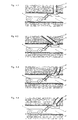
- Figur 1 : eine erste Ausführungsform der Trage- und Positioniervorrichtung,
- Figur 2 : eine zweite Ausführungsform,
- Figur 3: eine dritte Ausführungsform,
- Figur 4 : die Verwendung der erfindungsgemäßen Vorrichtung in Verbindung mit einer der ersten Ausführungsform entsprechenden Trage- und Positioniervorrichtung zum Abdichten von verschiedenartig zum Hauptkanal verlaufenden Nebenkanalanschlüssen.
- FIG. 1: a first embodiment of the carrying and positioning device,
- FIG. 2: a second embodiment,
- FIG. 3: a third embodiment,
- FIG. 4: the use of the device according to the invention in connection with a carrying and positioning device corresponding to the first embodiment for sealing secondary channel connections running differently to the main channel.
Nach einer ersten, in Figur 1 schematisch dargestellten Ausführungsform ist die Trage- und Positioniervorrichtung ein fernsteuerbarer Kanalsanierungsroboter. An dessen in drei Freiheitsgraden bewegbarem Kopf ist der Schild 1 befestigt, der mittels des von außen steuerbaren Kopfantriebs zusammen mit dem Dehnkörper 2 im Anschlußbereich des Nebenkanals 3 an den Hauptkanal 4 positioniert werden kann.According to a first embodiment, shown schematically in FIG. 1, the carrying and positioning device is a remote-controllable sewer rehabilitation robot. On its head, which can be moved in three degrees of freedom, the shield 1 is fastened, which can be positioned by means of the externally controllable head drive together with the expansion body 2 in the connection region of the secondary duct 3 to the main duct 4.
Mit Figur 2 ist dargestellt, daß die Trage- und Positioniervorrichtung auch eine Spannvorrichtung 6 umfassen kann, die sich gegen den dem Schild 1 radial gegenüberliegenden Wandungsbereich des Hauptkanals 4 abstützt und den Schild 1 im Kanalanschlußbereich anpreßt.FIG. 2 shows that the carrying and positioning device can also comprise a tensioning device 6, which is supported against the wall area of the main channel 4 radially opposite the plate 1 and presses the plate 1 in the channel connection area.
Figur 3 zeigt in schematischer Darstellung, daß die Trage- und Positioniervorrichtung auch ein Schlitten 7 sein kann, an dem der Schild 1 mit dem Dehnkörper 2 um eine zur Achse des Hauptkanals 4 parallele Drehachse drehbar befestigt ist. Der Schild 1 ist auf diese Weise besonders zuverlässig in Umfangsrichtung des Hauptkanals 4 positionierbar. Der Schlitten 7 weist Mittel zum Anpressen des Schildes 1 an die Wandung des Hauptkanals 4 auf.Figure 3 shows a schematic representation that the carrying and positioning device can also be a
Aus Figur4 ist anhand der dargestellten vier Beispiele ersichtlich, wie der Dehnkörper2 in verschiedenartig zum Hauptkanal verlaufende Nebenkanäle 3 hineinwächst, wobei anfänglich noch ein Zwischenraum zurwandung des Nebenkanals 3 vorhanden ist, der bei zunehmendem Aufblasen des Dehnkörpers 2 vollständig verschwindet, so daß der Dehnkörper 2 schließlich überall fest an der Wand anliegt.From the four examples shown in FIG. 4, it can be seen how the expansion body 2 grows into secondary channels 3 which run in different ways from the main channel, with an intermediate space for the wall of the secondary channel 3 initially being present, which completely disappears with increasing inflation of the expansion body 2, so that the expansion body 2 finally is firmly against the wall everywhere.
Es sei ausdrücklich darauf hingewiesen, daß die Figuren den Dehnkörper 2 lediglich schematisch darstellen. Seine anfängliche, beziehungsweise sich bei Druckbeaufschlagung einstellende spezielle Raumform entspricht der textlichen Beschreibung oben und den Angaben des Patentanspruchs 1.It should be expressly pointed out that the figures represent the expansion body 2 only schematically. Its initial spatial shape, or that which arises when pressure is applied, corresponds to the textual description above and the details of patent claim 1.
- 1 Schild1 sign
- 2 Dehnkörper2 expansion bodies
- 3 Nebenkanal3 secondary channel
- 4 Hauptkanal4 main channel
- 5 Kanalsanierungsroboter5 sewer renovation robots
- 6 Spannvorrichtung6 tensioning device
- 7 Schlitten7 sledges
Claims (9)
dadurch gekennzeichnet,
daß der Dehnkörper (2) ausschließlich aus einer Schicht elastischen Materials gebildet ist,
daß der Dehnkörper (2) in schwach aufgeblasenem Zustand zunächst die Form eines von dem Schild (1) ausgehenden, an der Spitze abgerundeten Hohlkegels einnimmt, die bei zunehmendem Aufblasen in eine dem Durchmesser des Nebenkanals (3) und seiner Abwinkelung zum Hauptkanal (4) entsprechende Zylinderform übergeht, wobei der Dehnkörper (2) zunehmend in den Nebenkanal (3) hineinwächst, und daß der Dehnkörper (2) durch Verminderung des ihn beaufschlagenden Druckes aus dem Nebenkanal (3) ausbringbar ist.1.Device for sealing channel walls in the area of the connection of a secondary channel (3) to a main channel (4), with a carrying and positioning device which can be moved and fixed in the main channel (4) for a in the area of the secondary channel connection to the wall of the main channel ( 4) can be applied, the wall curvature adaptable shield (1) which carries an inflatable expansion body (2) which can be inserted into the secondary duct (3), which in the inflated state rests against the wall of the secondary duct (3) and then together with the shield (1 ) forms a formwork in such a way that a sealing compound can be pressed into the space between this formwork and the adjacent walls of the main and secondary channels (4,3), which after the expansion body (2) has been removed from the secondary channel (3) and removing the shield (1) from the duct connection region forms sealed duct wall regions,
characterized,
that the expansion body (2) is formed exclusively from a layer of elastic material,
that the expansion body (2) in the slightly inflated state initially takes the form of a hollow cone starting from the shield (1) and rounded off at the tip, which, as the air inflates, increases into a diameter of the secondary channel (3) and its angling to the main channel (4) Corresponding cylindrical shape changes, the expansion body (2) growing increasingly into the secondary channel (3), and that the expansion body (2) can be brought out of the secondary channel (3) by reducing the pressure acting on it.
Applications Claiming Priority (2)
| Application Number | Priority Date | Filing Date | Title |
|---|---|---|---|
| DE4417076 | 1994-05-17 | ||
| DE19944417076 DE4417076C2 (en) | 1994-05-17 | 1994-05-17 | Device for sealing duct walls in the area of the connection of a secondary duct to a main duct |
Publications (2)
| Publication Number | Publication Date |
|---|---|
| EP0683348A2 true EP0683348A2 (en) | 1995-11-22 |
| EP0683348A3 EP0683348A3 (en) | 1997-09-03 |
Family
ID=6518172
Family Applications (1)
| Application Number | Title | Priority Date | Filing Date |
|---|---|---|---|
| EP95107387A Withdrawn EP0683348A3 (en) | 1994-05-17 | 1995-05-16 | Device for sealing the wall of a pipe at the junction between a main and a lateral pipe. |
Country Status (2)
| Country | Link |
|---|---|
| EP (1) | EP0683348A3 (en) |
| DE (1) | DE4417076C2 (en) |
Cited By (4)
| Publication number | Priority date | Publication date | Assignee | Title |
|---|---|---|---|---|
| WO1996041095A1 (en) * | 1995-06-07 | 1996-12-19 | D.T.I. Dr. Trippe | Device for repairing damaged areas of conduits, pipelines or the like |
| DE19956421A1 (en) * | 1999-11-24 | 2001-06-13 | Karlsruhe Forschzent | Inspection robot for pipeline system, has inspection devices supported by spiral deflection arms fitted to front end of carriage displaced along pipeline via relatively rotatable tubular housing |
| EP1519100A1 (en) * | 2003-09-25 | 2005-03-30 | Epros GmbH | Apparatus and method of renovating pipes |
| EP4239135A1 (en) * | 2022-03-01 | 2023-09-06 | Pipetronics GmbH & Co. KG | System for renovating damaged line walls in the region of the connection of an auxiliary line to a main line |
Families Citing this family (8)
| Publication number | Priority date | Publication date | Assignee | Title |
|---|---|---|---|---|
| DE19640698A1 (en) * | 1996-10-02 | 1998-04-16 | Willi Schwalm | Seal for repairing drain water pipe |
| DE19640697C2 (en) * | 1996-10-02 | 1999-02-25 | Willi Schwalm | Device for transporting and manipulating a tool in a sewer network |
| DE19641365C2 (en) * | 1996-10-08 | 2000-09-21 | Jt Elektronik Gmbh | Device for renovating the branch point of a house connection to a sewer pipe |
| DE19644466A1 (en) * | 1996-10-25 | 1998-04-30 | Herbert Dietrich | Renovation equipment |
| DE19758429C2 (en) * | 1997-01-11 | 2002-09-19 | Scheiff Gmbh | Device for lining a pipe branch of a sewer pipe |
| DE19700784C1 (en) * | 1997-01-11 | 1998-08-27 | Scheiff Gmbh | Drainage pipe lining process |
| DE19904475C2 (en) * | 1999-02-04 | 2002-11-21 | Bkp Berolina Polyester | Method and device for the rehabilitation of a line section of a pipeline as well as suitable flat material or connecting piece |
| DE10304934A1 (en) * | 2003-02-06 | 2004-09-16 | Bauer, Jens, Dipl.-Ing. | Method for sealing drain connection into main drain has a sealing collar fitted onto an inflatable flexible pressure body and positioned by a remote controlled trolley |
Family Cites Families (6)
| Publication number | Priority date | Publication date | Assignee | Title |
|---|---|---|---|---|
| US4484602A (en) * | 1983-01-17 | 1984-11-27 | Cues, Inc. | Packer for sealing lateral lines |
| DE3618963A1 (en) * | 1986-06-05 | 1987-12-10 | Adolf Prof Dipl Ing Voss | Process and apparatus for connecting a sewage pipe to a service pipe or the like which opens transversely therein |
| DE3810437A1 (en) * | 1988-03-26 | 1989-10-12 | Hemscheidt Maschf Hermann | METHOD FOR CONNECTING THE INLINER OF A CHANNEL PIPELINE TO THE INLET PIPES |
| CH682945A5 (en) * | 1989-12-01 | 1993-12-15 | Sika Robotics Ag | Remote controlled formwork installation in inaccessible pipe branches and junctions. |
| DE4213898A1 (en) * | 1991-05-18 | 1992-11-19 | Franz Janssen | Remote control repair equipment for underground conduits - has TV camera attached to removably insertable extension |
| DE9401637U1 (en) * | 1994-02-01 | 1995-01-12 | Schümann, Walter, 83059 Kolbermoor | Device for cutting plate-shaped objects |
-
1994
- 1994-05-17 DE DE19944417076 patent/DE4417076C2/en not_active Expired - Fee Related
-
1995
- 1995-05-16 EP EP95107387A patent/EP0683348A3/en not_active Withdrawn
Non-Patent Citations (1)
| Title |
|---|
| None |
Cited By (6)
| Publication number | Priority date | Publication date | Assignee | Title |
|---|---|---|---|---|
| WO1996041095A1 (en) * | 1995-06-07 | 1996-12-19 | D.T.I. Dr. Trippe | Device for repairing damaged areas of conduits, pipelines or the like |
| DE19956421A1 (en) * | 1999-11-24 | 2001-06-13 | Karlsruhe Forschzent | Inspection robot for pipeline system, has inspection devices supported by spiral deflection arms fitted to front end of carriage displaced along pipeline via relatively rotatable tubular housing |
| DE19956421C2 (en) * | 1999-11-24 | 2002-02-14 | Karlsruhe Forschzent | Inspection robot for pipe systems |
| EP1519100A1 (en) * | 2003-09-25 | 2005-03-30 | Epros GmbH | Apparatus and method of renovating pipes |
| US7631665B2 (en) | 2003-09-25 | 2009-12-15 | Trelleborg Pipe Seals Duisburg Gmbh | Device and method for pipeline rehabilitation |
| EP4239135A1 (en) * | 2022-03-01 | 2023-09-06 | Pipetronics GmbH & Co. KG | System for renovating damaged line walls in the region of the connection of an auxiliary line to a main line |
Also Published As
| Publication number | Publication date |
|---|---|
| DE4417076A1 (en) | 1995-11-23 |
| EP0683348A3 (en) | 1997-09-03 |
| DE4417076C2 (en) | 1996-08-01 |
Similar Documents
| Publication | Publication Date | Title |
|---|---|---|
| DE4417076C2 (en) | Device for sealing duct walls in the area of the connection of a secondary duct to a main duct | |
| EP0499153B1 (en) | Process for partially restoring a sewer buried in the ground | |
| WO2017202493A1 (en) | Sealing sleeve for pipe offsets | |
| EP0533999B1 (en) | Method for sealing pipelines | |
| DE9407896U1 (en) | Device for sealing duct walls in the area of the connection of a secondary duct to a main duct | |
| DE19702649C2 (en) | Device for the rehabilitation of sewer pipes | |
| DE19835315A1 (en) | Pipe-repairing equipment, e.g. for sewers | |
| DE19601041C2 (en) | Method and device for the rehabilitation of socket connection areas of sewage pipes and sewers | |
| EP1998099B1 (en) | Apparatus for renovating pipes | |
| DE19733029C2 (en) | Process for the rehabilitation of a pipeline, especially for civil engineering | |
| DE4418331C2 (en) | Method and device for closing a branch line opening into a main line | |
| DE102008008296B4 (en) | Method and remote controlled device for internal pipe work | |
| EP0677690B1 (en) | Socket butt sealing | |
| EP4038306A1 (en) | Device for renovating a conduit, in which an expansion element locks in place | |
| EP0493862B1 (en) | Method and device for the restoration of pipe-lines | |
| DE9400793U1 (en) | Device for sealing leak parts in pipes from inside the pipe | |
| EP0370193B1 (en) | Process for the partial reconstruction of pipes, especially drainpipes | |
| DE4418330C2 (en) | Method and device for repairing the walls in the connection area of a branch pipe to a main pipe | |
| DE19824773C2 (en) | Device and method for repairing pipes | |
| DE102020134023B4 (en) | Sleeve connection device, manufacturing method and method for integrating or renovating connections | |
| DE19717209A1 (en) | Pipe leak repair cuff surrounding pipe | |
| EP1892451A2 (en) | Method for repairing defects in conduits and ducts without digging | |
| EP0467024A1 (en) | Method for sealing the butt gap between buried pipeline sections and device and sealing element to carry out the method | |
| EP0436060A1 (en) | Method of relining of cavities, especially for the renovation of damaged ducts and pipelines | |
| EP0350802A1 (en) | Method for reconstructing pipe-lines |
Legal Events
| Date | Code | Title | Description |
|---|---|---|---|
| PUAI | Public reference made under article 153(3) epc to a published international application that has entered the european phase |
Free format text: ORIGINAL CODE: 0009012 |
|
| AK | Designated contracting states |
Kind code of ref document: A2 Designated state(s): AT CH DE FR LI |
|
| PUAL | Search report despatched |
Free format text: ORIGINAL CODE: 0009013 |
|
| AK | Designated contracting states |
Kind code of ref document: A3 Designated state(s): AT CH DE FR LI |
|
| 17P | Request for examination filed |
Effective date: 19980303 |
|
| 17Q | First examination report despatched |
Effective date: 19991208 |
|
| GRAG | Despatch of communication of intention to grant |
Free format text: ORIGINAL CODE: EPIDOS AGRA |
|
| GRAG | Despatch of communication of intention to grant |
Free format text: ORIGINAL CODE: EPIDOS AGRA |
|
| GRAH | Despatch of communication of intention to grant a patent |
Free format text: ORIGINAL CODE: EPIDOS IGRA |
|
| STAA | Information on the status of an ep patent application or granted ep patent |
Free format text: STATUS: THE APPLICATION IS DEEMED TO BE WITHDRAWN |
|
| 18D | Application deemed to be withdrawn |
Effective date: 20000918 |
|
| RAP1 | Party data changed (applicant data changed or rights of an application transferred) |
Owner name: D.T.I. DR. TRIPPE INGENIEURGES. MBH. |