EP0683079A1 - Recovery vehicle for an aerial ropeway - Google Patents
Recovery vehicle for an aerial ropeway Download PDFInfo
- Publication number
- EP0683079A1 EP0683079A1 EP95810322A EP95810322A EP0683079A1 EP 0683079 A1 EP0683079 A1 EP 0683079A1 EP 95810322 A EP95810322 A EP 95810322A EP 95810322 A EP95810322 A EP 95810322A EP 0683079 A1 EP0683079 A1 EP 0683079A1
- Authority
- EP
- European Patent Office
- Prior art keywords
- basket
- salvage
- cable
- recovery
- rope
- Prior art date
- Legal status (The legal status is an assumption and is not a legal conclusion. Google has not performed a legal analysis and makes no representation as to the accuracy of the status listed.)
- Ceased
Links
Images


Classifications
-
- B—PERFORMING OPERATIONS; TRANSPORTING
- B61—RAILWAYS
- B61B—RAILWAY SYSTEMS; EQUIPMENT THEREFOR NOT OTHERWISE PROVIDED FOR
- B61B3/00—Elevated railway systems with suspended vehicles
-
- B—PERFORMING OPERATIONS; TRANSPORTING
- B61—RAILWAYS
- B61B—RAILWAY SYSTEMS; EQUIPMENT THEREFOR NOT OTHERWISE PROVIDED FOR
- B61B12/00—Component parts, details or accessories not provided for in groups B61B7/00 - B61B11/00
- B61B12/005—Rescue devices for passengers
Definitions
- the invention relates, on the one hand, to a rescue vehicle for the transport vehicles of a cable car, with a carriage conveyed on at least one support rope and at least one traction rope, with a salvage basket and with a hanger which is pivotally mounted on the drive and on which the salvage basket hangs below, the salvage basket opposite Drive with a traction device from a driving position to a salvage position can be lowered or raised.
- the invention relates to a rescue vehicle for the transport vehicles of a cable car, with a hanger which is pivotally mounted on at least one carrying pull rope and on which a rescue basket hangs at the bottom, the rescue basket being moved from a driving position to a pulling device with respect to its reception on the carrying pull rope Salvage position can be lowered or raised.
- cable cars are to be equipped with an emergency vehicle if an area is difficult to walk on, on which the passengers cannot be roped down. Thanks to the high level of operational safety achieved by cable cars today, the recovery vehicles are practically almost unused facilities, since such emergencies generally do not occur. However, the rescue vehicles must always be available for use in accordance with the regulations for emergencies and an annual inspection of the vehicles is provided, in which their operational readiness and functionality is determined and approved.
- the hanger In a known recovery vehicle with the features mentioned above, which is provided for a cable car with two suspension cables for the transport vehicle, on which the recovery vehicle is also conveyed, the hanger consists of several square tubes articulated at their ends.
- the upper square tube hangs on Undercarriage, the salvage cage is firmly attached to the lower square tube and can be brought to the required height in several stages with a cable pulling device to the transport vehicle and locked on the square tube.
- the plurality of joints are designed as locking joints which snap into place between the square tubes.
- the well-known recovery vehicle is parked in the mountain station. Since the extended hanger is too long with its salvage basket reaching below the platform, the entire salvage vehicle with the drive is removed from the carrying cables and stored in a storage space at the mountain station.
- the salvage basket is removed from the hanger, the hanger can be folded up in the locking joints and the square tubes fastened to each other next to each other. Removing the recovery vehicle from the suspension cables or putting it back on the suspension cables until it is ready for operation takes a long time and is also a very dangerous matter.
- the task is to be solved to park the entire salvage vehicle, i.e. drive with suspension including salvage basket and pulling device, in a very confined space and to keep it fully functional and ready for use.
- the hanger consists of several traction means, preferably wire ropes, on which the traction means of the traction device acts.
- the multiple wire ropes of the suspension alternatively chains can be provided, form a (statically determined) truss, the tension rods of which consist of traction means; the clamping points or deflections of the traction means are the joints of the framework.
- the half-timbered construction gives the hanger according to the invention the necessary stability against pendulum movements around the three axes of the spatial coordinate system.
- fixed fixings of the suspension cables can also be provided.
- the rescue vehicle according to the invention is therefore resistant to disturbances during driving when driving over supports and very stable against wind influences, since it has only one, but necessary, joint in which pendulum movements are possible, through which the hanger, including the salvage basket, adapts to the different inclinations on the conveyor line. Because of the flexible half-timbered construction, the drive, hangers and salvage basket of the salvage vehicle according to the invention can be contracted while slackening the traction means of the hangers.
- a traction device is provided, as is known for example from DE 36 04 365 C2, which acts on the taut traction means of the hanger.
- the lane can consist of a support cable or two support cables and have a separate pull cable, or two of them.
- the pull rope for the recovery vehicle can belong to a winch or be guided all the way round.
- the lane of the recovery vehicle can also be the lane of the transport vehicle, for example in the case of a cable car; however, it is also possible to set up a separate lane only for the recovery vehicle between the two lanes for the transport vehicles, for example in the case of a cable car, in which case the recovery vehicle can also convey into the valley station.
- the support rope can also be a pull rope; in this case, the suspension cable has a rotating cable drive and in turn a separate lane is set up only for the recovery vehicle between the two lanes for the transport vehicles; two carrying cables can also be provided.
- the invention has a four-point suspension, consisting of four equally long wire ropes, between an upper and a lower crossbar stretched, each attack on an upper corner of the salvage basket and from there to the cable pulling device.
- This inventive design of the truss gives the hanger together with the salvage basket high stability against tipping about one of the two horizontal axes with asymmetrical loading.
- a particularly stable hanger with additional struts results in the invention if the four wire cables are each clamped at one end at the corner point of the lower crossmember, deflected at a corner point of the upper crossbar and attack at the opposite corner point of the salvage cage.
- the four wire cables of the hanger are guided on the load hooks of the cable pulling device arranged in the center of the recovery cage, which acts with its pulling rope on the lower crossbar of the hanger.
- the four wire ropes in the invention are unwound or wound up by a rope drum which is accommodated in the bottom of the recovery cage and accordingly has multiple grooves and on which they engage in the same direction of rotation, and the pulling rope of the rope pulling device engages in a further groove of the rope drum in the opposite direction a.
- the salvage basket is therefore free of hanging ropes. In the salvage position, the cable drum is locked on the ground.
- stops are provided on the recovery vehicle to limit the total stroke when lifting or lowering the recovery basket on the cable drum, which cooperate with a stop on the bottom of the recovery basket and permit approximately one full rotation of the cable drum.
- two bolts in pin holes on the bottom of the salvage basket can be repositioned to limit the partial stroke when lifting or lowering the salvage basket, strike the spokes of the cable drum and enable gradual lowering or lifting of the salvage basket.
- the rescue vehicle which is conveyed in the driving position to the mountain station, can be placed under another cable pulling device Slacken the slack in the sling in the direction of the drive from the driving position into a parking position.
- the second cable pull device always remains in the top station, is hung there for parking the recovery vehicle on the upper crossbar of the suspension and attacks with four pull cables at the corners on the bottom of the recovery basket; it remains in engagement in the parked recovery vehicle.
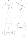
- a recovery vehicle is designated by 1 in total. It consists of a drive 2, a salvage basket 3 and a hanger 4 between drive 2 and salvage basket 3; the salvage basket 3 hangs on the bottom of four wire ropes of the hanger 4.
- the drive 2 shown is intended for a lane consisting of two suspension cables. 1b it has a rectangular frame 2 1. At the four corners of the frame 2 1 22 wheels are attached, which roll on the two cables of a cable car. In the case of a single cable car, at least two running wheels are provided on the running gear for stable guidance on the standing cable. With the frame 2 1 a triangular suspension 2 3 is firmly connected in the side view, at the lower corner of which a hinge 2 3 1 is arranged for pivotally accommodating the hanger 4 on the drive 2.
- the hanger 4 consists of an upper 431 and a lower cross member 42 and four equally long wire ropes 41. Both trusses 42 and 431 have rectangular frames.
- the upper cross member 431 is extended with a vertical rod 432 upwards and at the end of its extension in the joint 231 on the drive 2nd articulated. Between the two trusses 42 and 43 and the salvage basket 3, the four wire ropes 41 are stretched:
- Each wire rope 41 is attached at one end to a corner point of the rectangular frame of the lower cross member 42, is deflected at the diagonally opposite corner point of the upper cross member 431 and led to the associated corner point of the lower cross member 42. There it can be deflected and attack the associated upper corner point of the recovery cage 3 and in turn deflected by means of a roller 3 1 arranged there to be continued to a cable pulling device, not shown in FIG.
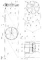
- the lower guide rollers 32 steer the suspension cables 41 from the vertical to the horizontal and guide them to a cable drum 6 housed in the bottom of the recovery basket 3, on which they are wound in the same direction.
- Fig.2c the leadership of a single wire rope 411 on the rope drum 6 is shown wound, which corresponds to the driving position of the recovery vehicle 1 according to Fig.2a.
- the four suspension cables 411 to 414 are each attached at one end via a cable clamp 45 and a cable lock 44 to a corner of the lower cross member 42 and at the other end comprise the cable drum shaft 63 with a cable loop 46.
- a cable pulling device For lowering or lifting the recovery vehicle 1, a cable pulling device , generally designated 5, is provided according to FIG .
- the pulling device 5 1 is attached to one side of the recovery basket 3, as can be seen from FIG. 3 a, and engages with its pulling rope 5 2 in the opposite direction to the four suspension cables 4 11 to 4 1 on the cable drum 6.
- the cable routing of a total of five traction ropes, these are the four suspension ropes 411 to 414 and the traction rope 52 of the cable pulling device 5, on the cable drum 6 can be seen from the detail identified in Fig.3b with IIIc from Fig.3c.
- the cable drum 6 is shown removed from its storage 36 on a cross member 34 of the bottom frame 33.
- the cable ring 6 1 of the cable drum 6 is connected via spokes 6 2 to the receptacle for the cable drum shaft 6 3.
- On the lower bearing plate 64 two stops 641 and 642 are formed, which cooperate with a corresponding stop 35 on the floor frame 33 and between the upper stop 641 and the lower stop 642 allow approximately a full rotation of the cable drum 6.
- four bolt holes 371 to 374 are arranged on the cross member 34 of the base frame 33, which cooperate with the spokes 62 of the cable drum 6 to limit the partial stroke when lowering or lifting the recovery vehicle 1 via two insertable bolts 71 and 72.
- the total stroke limitation and the partial stroke limitation when lowering or lifting the recovery vehicle 1 is explained in detail with reference to FIG. 4:
- Fig.4a The total stroke limitation is shown in Fig.4a.
- the salvage cage 3 is at the top in the driving position F, and the cable drum 6 is turned to the bottom stop 642 of the cable drum 6 at the bottom stop 35 to the right; in Fig.4a II the upper stop 641 strikes after almost a complete left turn of the cable drum 6 at the bottom stop 35, the recovery basket 3 is located below in the recovery position B.
- Fig.4b shows the partial stroke limits in individual positions I to VIII.
- the two bolts 71 and 72 can be repositioned in the four bolt holes 371 to 374 on the floor frame 33 and allow a gradual lowering or lifting of the recovery basket 3 by means of the cable 5 from the driving - F to salvage position B:
- Fig.4b I corresponds to Fig.4a I.
- the cable 5 is the unwinding of the salvage basket 3 by about 30 ° rotation angle the cable drum 6 possible until the two bolts 7 1 and 7 2 as shown in FIG. 4b II strike the next spoke 62 in the direction of rotation.
- Bolt 72 secures during the change.
- Fig.4b IV bolt 72 is plugged into hole 372 and bolt 71 secures during the plugging. Then a lowering by a further 30 ° angle of rotation of the cable drum 6 is possible until the two bolts 7 1 and 7 2 as shown in FIG. 4b V strike the spoke 6 2 following in the direction of rotation again.
- Fig.4b VI bolt 71 is inserted into hole 373, bolt 72 secures during the change; thereafter can be changed according to Fig.4b VII bolt 72 in hole 374, while bolt 71 secures, according to Fig.4b VIII a further lowering by about 30 ° angle of rotation of the cable drum 6 is possible until the next spoke 62 on the two bolts 71 , 72 strikes.
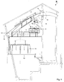
- the recovery vehicle 1 is brought from its driving position F shown in FIG. 5a (corresponds to FIG. 1b), in which it extends from the mountain station and is returned to it, into a parking position P according to FIG. 5c which it is parked in the mountain station.
- a second cable pulling device 8 is installed, which engages one end with four pulling ropes 822 at the corners at the bottom of the salvage basket 3 and the other end is hung with another pulling rope 821 on the upper cross member 43 of the hanger 4.
- the salvage vehicle 1 to be garaged is essentially unloaded by means of the second cable 8 by an operator, slackening the wire cables 4 1 of the hanger 4, until it has reached the parking position P shown in FIG.
- 5 c in which it contracts in the vertical direction in a confined space is; the second cable pulling device 8 remains in the parking position P, in the lowered driving position F it is removed and remains at the top station.
- 5b is an intermediate position shown, in which the lower cross member 42 of the hanger 4 comes into contact with the salvage basket 3.
- the cable car is a pendulum cable car with two lanes, which are formed by two supporting cables 13 each.
- the top station is designated B, the transport vehicle stopping at the top station B is designated 11; the other transport vehicle is at the valley station.
- the passengers get on and off on a shifting platform 12 that serves both lanes.
- the two suspension ropes 13 of the cable car rest on a rope saddle 14 and at the same time serve as suspension ropes 13 for the recovery vehicle 1.
- 15 is a deflection wheel for the revolving pull rope of the transport vehicle 11.
- the salvage vehicle 1 is parked in front of a platform 16 in the parking position P shown in FIG. 5c, together with the engaged second cable pulling device 8, on the cable saddle 14.
- a salvage winch 9 is arranged in the ridge of the mountain station B and attacks with its pull rope on the joint 2 3 between the drive 2 and the hanger 4.
- a third cable pulling device 10 is provided, the load hook of which is hooked on one end to the masonry of the mountain station B and the other end engages with its pulling rope on the frame of the drive 2 and provides a slack pulling rope on the recovery winch 9.
- the third cable apparatus 10 can be handled from the platform 16.
- the complete recovery vehicle 1, parked essentially unnoticed, is always ready for use.
Abstract
Description
Die Erfindung betrifft zum einen ein Bergungsfahrzeug für die Transportfahrzeuge einer Seilbahn, mit an zumindest einem Tragseil und an zumindest einem Zugseil geförderten Laufwerk, mit einem Bergungskorb und mit einem am Laufwerk schwenkbeweglich aufgenommenen Gehänge, an dem unten der Bergungskorb hängt, wobei der Bergungskorb gegenüber dem Laufwerk mit einem Zugapparat aus einer Fahrstellung in eine Bergungsstellung ablaßbar bzw. hebbar ist.The invention relates, on the one hand, to a rescue vehicle for the transport vehicles of a cable car, with a carriage conveyed on at least one support rope and at least one traction rope, with a salvage basket and with a hanger which is pivotally mounted on the drive and on which the salvage basket hangs below, the salvage basket opposite Drive with a traction device from a driving position to a salvage position can be lowered or raised.
Zum anderen betrifft die Erfindung ein Bergungsfahrzeug für die Transportfahrzeuge einer Seilbahn, mit einem an zumindest einem Trag-Zugseil schwenkbeweglich aufgenommenem Gehänge, an dem unten ein Bergungskorb hängt, wobei der Bergungskorb gegenüber seiner Aufnahme am Trag-Zugseil mit einem Zugapparat aus einer Fahrstellung in eine Bergungsstellung ablaßbar bzw. hebbar ist.On the other hand, the invention relates to a rescue vehicle for the transport vehicles of a cable car, with a hanger which is pivotally mounted on at least one carrying pull rope and on which a rescue basket hangs at the bottom, the rescue basket being moved from a driving position to a pulling device with respect to its reception on the carrying pull rope Salvage position can be lowered or raised.
Nach internationalen Standards sind Seilbahnen für den Notfall mit einem Bergungsfahrzeug auszurüsten, wenn ein schlecht begehbares Gelände überfahren wird, auf dem die Passagiere nicht abgeseilt werden können. Dank der heute allgemein erreichten hohen Betriebssicherheit von Seilbahnen handelt es sich bei den Bergungsfahrzeugen um praktisch fast nicht gebrauchte Einrichtungen, da solche Notfälle im allgemeinen nicht vorkommen. Die Bergungsfahrzeuge müssen aber nach den Vorschriften für den Notfall stets einsatzbereit zur Verfügung stehen und es ist alljährlich einmal eine Überprüfung der Fahrzeuge vorgesehen, bei der ihre Einsatzbereitschaft und Funktionsfähigkeit festgestellt und abgenommen wird.According to international standards, cable cars are to be equipped with an emergency vehicle if an area is difficult to walk on, on which the passengers cannot be roped down. Thanks to the high level of operational safety achieved by cable cars today, the recovery vehicles are practically almost unused facilities, since such emergencies generally do not occur. However, the rescue vehicles must always be available for use in accordance with the regulations for emergencies and an annual inspection of the vehicles is provided, in which their operational readiness and functionality is determined and approved.
Bei einem bekannten Bergungsfahrzeug mit den eingangs genannten Merkmalen, das für eine Pendelseilbahn mit zwei Tragseilen für das Transportfahrzeug vorgesehen ist, an denen auch das Bergungsfahrzeug gefördert wird, besteht das Gehänge aus mehreren, an ihren Enden gelenkig zusammengesteckten Vierkantrohren. Das obere Vierkantrohr hängt schwenkbeweglich am Laufwerk, am unteren Vierkantrohr ist der Bergungskorb unten fest angebracht und kann mit einem Seilzugapparat in mehreren Stufen auf die erforderliche Höhenlage zum Transportfahrzeug gebracht und am Vierkantrohr verriegelt werden. Die mehreren Gelenke sind als Rastgelenke ausgebildet, die in der Strecklage zwischen den Vierkantrohren einrasten. Das bekannte Bergungsfahrzeug wird in der Bergstation abgestellt. Da das ausgefahrene Gehänge zu lang ist, mit seinem Bergungskorb bis unter den Perron reicht, wird das gesamte Bergungsfahrzeug mit dem Laufwerk von den Tragseilen abgenommen und in einem Stauraum der Bergstation aufbewahrt. Der Bergungskorb wird vom Gehänge entfernt, das Gehänge läßt sich in den Rastgelenken zusammenklappen und die Vierkantrohre nebeneinanderliegend aneinander befestigen. Das Abnehmen des Bergungsfahrzeugs von den Tragseilen bzw. sein Wiederaufsetzen auf die Tragseile bis zur Betriebsbereitschaft dauert recht lange und ist im übrigen eine sehr gefährliche Angelegenheit.In a known recovery vehicle with the features mentioned above, which is provided for a cable car with two suspension cables for the transport vehicle, on which the recovery vehicle is also conveyed, the hanger consists of several square tubes articulated at their ends. The upper square tube hangs on Undercarriage, the salvage cage is firmly attached to the lower square tube and can be brought to the required height in several stages with a cable pulling device to the transport vehicle and locked on the square tube. The plurality of joints are designed as locking joints which snap into place between the square tubes. The well-known recovery vehicle is parked in the mountain station. Since the extended hanger is too long with its salvage basket reaching below the platform, the entire salvage vehicle with the drive is removed from the carrying cables and stored in a storage space at the mountain station. The salvage basket is removed from the hanger, the hanger can be folded up in the locking joints and the square tubes fastened to each other next to each other. Removing the recovery vehicle from the suspension cables or putting it back on the suspension cables until it is ready for operation takes a long time and is also a very dangerous matter.
Demgegenüber soll die Aufgabe gelöst werden, das gesamte Bergungsfahrzeug, also Laufwerk mit Gehänge samt Bergungskorb und Zugapparat, auf engstem Raum abzustellen und funktionsfähig aneinandergebaut einsatzbereit verfügbar zu halten.In contrast, the task is to be solved to park the entire salvage vehicle, i.e. drive with suspension including salvage basket and pulling device, in a very confined space and to keep it fully functional and ready for use.
Diese Aufgabe wird erfindungsgemäß mit den Merkmalen gelöst, daß das Gehänge in Fachwerkbauweise aus mehreren Zugmitteln, vorzugsweise Drahtseilen, besteht, an denen das Zugmittel des Zugapparats angreift.This object is achieved according to the invention with the features that the hanger consists of several traction means, preferably wire ropes, on which the traction means of the traction device acts.
Die mehreren Drahtseile des Gehänges, alternativ können auch Ketten vorgesehen sein, bilden ein (statisch bestimmtes) Fachwerk, dessen Zugstäbe aus Zugmitteln bestehen; die Einspannstellen bzw. Umlenkungen der Zugmittel sind die Gelenke des Fachwerks. Die Fachwerkbauweise verleiht dem erfindungsgemäßen Gehänge die erforderliche Stabilität gegenüber Pendelbewegungen um die drei Achsen des räumlichen Koordinatensystems. Anstatt Umlenkungen können auch feste Einspannungen der Gehängeseile vorgesehen sein.The multiple wire ropes of the suspension, alternatively chains can be provided, form a (statically determined) truss, the tension rods of which consist of traction means; the clamping points or deflections of the traction means are the joints of the framework. The half-timbered construction gives the hanger according to the invention the necessary stability against pendulum movements around the three axes of the spatial coordinate system. Instead of deflections, fixed fixings of the suspension cables can also be provided.
Das Bergungsfahrzeug nach der Erfindung ist deshalb gegenüber Störungen während des Fahrbetriebs beim Überfahren von Stützen und gegenüber Windeinflüssen sehr stabil, da es nur ein einziges, allerdings erforderliches, Gelenk hat, in dem Pendelbewegungen möglich sind, durch die sich das Gehänge samt Bergungskorb den unterschiedlichen Neigungen auf der Förderstrecke anpaßt. Wegen der flexiblen Fachwerkbauweise lassen sich Laufwerk, Gehänge und Bergungskorb des Bergungsfahrzeugs nach der Erfindung unter Erschlaffung der Zugmittel des Gehänges zusammenziehen.The rescue vehicle according to the invention is therefore resistant to disturbances during driving when driving over supports and very stable against wind influences, since it has only one, but necessary, joint in which pendulum movements are possible, through which the hanger, including the salvage basket, adapts to the different inclinations on the conveyor line. Because of the flexible half-timbered construction, the drive, hangers and salvage basket of the salvage vehicle according to the invention can be contracted while slackening the traction means of the hangers.
Um das erfindungsgemäße Bergungsfahrzeug aus der Fahrstellung, in der es von der Länge her so bemessen ist, daß es sich aus der Bergstation problemlos ausfahren und zum Transportfahrzeug fördern läßt, in die Bergungsstellung abzulassen, in der es auf die erforderliche Höhenlage zum Transportfahrzeug eingerichtet ist, ist ein Zugapparat vorgesehen, wie er bspw. durch die DE 36 04 365 C2 für sich bekannt ist, der an den straffen Zugmitteln des Gehänges angreift.In order to lower the recovery vehicle according to the invention from the driving position, in which its length is such that it can be easily extended from the mountain station and conveyed to the transport vehicle, into the recovery position, in which it is set up at the required altitude for the transport vehicle, a traction device is provided, as is known for example from
Bei der Erfindung kann die Fahrspur aus einem Tragseil oder aus zwei Tragseilen bestehen und ein separates Zugseil haben, oder deren zwei. Das Zugseil für das Bergungsfahrzeug kann zu einer Seilwinde gehören oder umlaufend geführt sein. Die Fahrspur des Bergungsfahrzeugs kann zugleich auch die Fahrspur des Transportfahrzeugs sein, bspw. im Falle einer Pendelseilbahn; es läßt sich aber auch eine eigene Fahrspur nur für das Bergungsfahrzeug zwischen den beiden Fahrspuren für die Transportfahrzeuge einrichten, bspw. im Falle einer Umlaufseilbahn, wobei dann das Bergungsfahrzeug auch in die Talstation fördern kann.In the invention, the lane can consist of a support cable or two support cables and have a separate pull cable, or two of them. The pull rope for the recovery vehicle can belong to a winch or be guided all the way round. The lane of the recovery vehicle can also be the lane of the transport vehicle, for example in the case of a cable car; however, it is also possible to set up a separate lane only for the recovery vehicle between the two lanes for the transport vehicles, for example in the case of a cable car, in which case the recovery vehicle can also convey into the valley station.
Bei der Erfindung kann das Tragseil auch zugleich Zugseil sein; in diesem Falle hat das Trag-Zugseil einen umlaufenden Seiltrieb und es ist wiederum eine eigene Fahrspur nur für das Bergungsfahrzeug zwischen den beiden Fahrspuren für die Transportfahrzeuge eingerichtet; es können auch zwei Trag-Zugseile vorgesehen sein.In the invention, the support rope can also be a pull rope; in this case, the suspension cable has a rotating cable drive and in turn a separate lane is set up only for the recovery vehicle between the two lanes for the transport vehicles; two carrying cables can also be provided.
An dem Gehänge ist aus Stabilitätsgründen zumindest eine Dreipunktaufhängung vorgesehen. Vorzugsweise hat die Erfindung eine Vierpunktaufhängung, bestehend aus vier gleich langen Drahtseilen, die zwischen einer oberen und einer unteren Traverse aufgespannt, jeweils an einer oberen Ecke des Bergungskorbs angreifen und von dort zum Seilzugapparat weitergeführt sind. Diese erfindungsgemäße Ausbildung des Fachwerks verleiht dem Gehänge samt Bergungskorb hohe Stabilität gegenüber Kippen um eine der beiden horizontalen Achsen bei unsymmetrischer Beladung.For reasons of stability, at least one three-point suspension is provided on the hanger. Preferably, the invention has a four-point suspension, consisting of four equally long wire ropes, between an upper and a lower crossbar stretched, each attack on an upper corner of the salvage basket and from there to the cable pulling device. This inventive design of the truss gives the hanger together with the salvage basket high stability against tipping about one of the two horizontal axes with asymmetrical loading.
Ein besonders stabiles Gehänge mit zusätzlichen Verstrebungen ergibt sich bei der Erfindung, wenn die vier Drahtseile jeweils mit ihrem einem Ende am Eckpunkt der unteren Traverse eingespannt sind, an einem Eckpunkt der oberen Traverse umgelenkt werden und mit ihrem anderen Ende am gegenüberliegenden Eckpunkt des Bergungskorbs angreifen.A particularly stable hanger with additional struts results in the invention if the four wire cables are each clamped at one end at the corner point of the lower crossmember, deflected at a corner point of the upper crossbar and attack at the opposite corner point of the salvage cage.
In einfachster Anordnung sind die vier Drahtseile des Gehänges an den Lasthaken des mittig im Bergungskorb angeordneten Seilzugapparats geführt, der mit seinem Zugseil an der unteren Traverse des Gehänges angreift. In vorteilhafter Weiterbildung werden die vier Drahtseile bei der Erfindung von einer im Boden des Bergungskorbs untergebrachten, dementsprechend mehrrillig ausgeführten Seiltrommel ab- bzw. aufgewickelt, an der sie im selben Drehsinn angreifen, und das Zugseil des Seilzugapparats greift im Gegendrehsinn in eine weitere Rille der Seiltrommel ein. Der Bergungskorb ist somit frei von hängenden Seilen. In der Bergungsstellung wird die Seiltrommel am Boden verriegelt.In the simplest arrangement, the four wire cables of the hanger are guided on the load hooks of the cable pulling device arranged in the center of the recovery cage, which acts with its pulling rope on the lower crossbar of the hanger. In an advantageous further development, the four wire ropes in the invention are unwound or wound up by a rope drum which is accommodated in the bottom of the recovery cage and accordingly has multiple grooves and on which they engage in the same direction of rotation, and the pulling rope of the rope pulling device engages in a further groove of the rope drum in the opposite direction a. The salvage basket is therefore free of hanging ropes. In the salvage position, the cable drum is locked on the ground.
In vorteilhafter Weiterbildung der Erfindung sind an dem Bergungsfahrzeug zur Gesamthubbegrenzung beim Heben bzw. Absenken des Bergungskorbs an der Seiltrommel Anschläge vorgesehen, die mit einem Anschlag am Boden des Bergungskorbs zusammenwirken und annähernd eine volle Umdrehung an der Seiltrommel zulassen.In an advantageous development of the invention, stops are provided on the recovery vehicle to limit the total stroke when lifting or lowering the recovery basket on the cable drum, which cooperate with a stop on the bottom of the recovery basket and permit approximately one full rotation of the cable drum.
In noch weiterer Ausbildung der Erfindung sind zur Teilhubbegrenzung beim Heben bzw. Absenken des Bergungskorbs zwei Bolzen in Bolzenlöchern am Boden des Bergungskorbs umsteckbar, schlagen an Speichen der Seiltrommel an und ermöglichen ein schrittweises Absenken bzw. Heben des Bergungskorbs.In yet another embodiment of the invention, two bolts in pin holes on the bottom of the salvage basket can be repositioned to limit the partial stroke when lifting or lowering the salvage basket, strike the spokes of the cable drum and enable gradual lowering or lifting of the salvage basket.
Das in der Fahrstellung zur Bergstation geförderte Bergungsfahrzeug läßt sich mit einem weiteren Seilzugapparat unter Erschlaffung der Zugmittel des Gehänges in Richtung Laufwerk aus der Fahrstellung in eine Parkstellung heben. Der zweite Seilzugapparat verbleibt stets in der Bergstation, wird dort zum Einparken des Bergungsfahrzeugs an der oberen Traverse des Gehänges eingehängt und greift mit vier Zugseilen an den Ecken am Boden des Bergungskorbs an; er verbleibt im abgestellten Bergungsfahrzeug montiert im Eingriff.The rescue vehicle, which is conveyed in the driving position to the mountain station, can be placed under another cable pulling device Slacken the slack in the sling in the direction of the drive from the driving position into a parking position. The second cable pull device always remains in the top station, is hung there for parking the recovery vehicle on the upper crossbar of the suspension and attacks with four pull cables at the corners on the bottom of the recovery basket; it remains in engagement in the parked recovery vehicle.
Ein bevorzugtes Ausführungsbeispiel nach der Erfindung wird nachstehend unter Bezugnahme auf die Zeichnung näher erläutert:A preferred embodiment according to the invention is explained in more detail below with reference to the drawing:
In
- Fig.1
- ist das Bergungsfahrzeug nach der Erfindung in einer Seitenansicht dargestellt;
- a) zeigt die Bergungsstellung,
- b) zeigt die Fahrstellung.
- Fig.2
- zeigt den Bergungskorb mit den Gehängeseilen in einer Perspektive,
- a) zeigt die Fahrstellung,
- b) zeigt die Bergungsstellung,
- c) zeigt die die Seilführung eines einzelnen Gehängeseils.
- Fig.3
- zeigt die Anordnung der Seiltrommel im Boden des Bergungsfahrzeugs zum Ablassen bzw. Heben des Bergungskorbs,
- a) ist eine Draufsicht auf die im Boden des Bergungskorbs untergebrachte Seiltrommel längs der Linie IIIa - IIIa in Fig.la,
- b) ist ein Schnitt durch die Seiltrommelwelle längs der Linie IIIb - IIIb in Fig.3a,
- c) zeigt den Eingriff der einzelnen Seile in die Laufrillen am Seilkranz der Seiltrommel gemäß der in Fig.3b gekennzeichneten Einzelheit IIIc und
- d) ist eine Draufsicht auf die von ihrer Lagerung am Bodenrahmen des Bergungskorbs abgenommene Seiltrommel. In
- Fig.4
- sind die Hubbegrenzungen beim Ablassen bzw. Heben des Bergungskorbs dargestellt,
- a) veranschaulicht die Gesamthubbegrenzung und
- b) die Teilhubbegrenzung.
- Fig.5
- zeigt in drei Seitenansichten, wie das erfindungsgemäße Bergungsfahrzeug mit einem weiteren Seilzugapparat aus der Fahrstellung gemäß Fig.1b in eine Parkstellung gebracht wird.
- a) ist die Fahrstellung gemäß Fig.1b,
- b) ist eine Zwischenstellung, bei der die untere Traverse des Gehänges zur Anlage an den Bergungskorb kommt und
- c) ist die Parkstellung. In
- Fig.6
- ist die Bergstation einer Pendelseilbahn in einer Seitenansicht und insbesondere die Garagierung des Bergungsfahrzeugs in der Parkstellung gemäß Fig.5c im Dachfirst der Bergstation dargestellt.
- Fig. 1
- the recovery vehicle according to the invention is shown in a side view;
- a) shows the salvage position,
- b) shows the driving position.
- Fig. 2
- shows the salvage basket with the suspension cables in one perspective,
- a) shows the driving position,
- b) shows the salvage position,
- c) shows the rope guidance of a single suspension rope.
- Fig. 3
- shows the arrangement of the cable drum in the floor of the recovery vehicle for lowering or lifting the recovery basket,
- a) is a plan view of the rope drum housed in the bottom of the salvage basket along the line IIIa - IIIa in Fig.la,
- b) is a section through the cable drum shaft along the line IIIb - IIIb in FIG. 3a,
- c) shows the engagement of the individual ropes in the grooves on the rope ring of the rope drum according to the detail IIIc and marked in Fig.3b
- d) is a top view of the cable drum removed from its storage on the bottom frame of the recovery cage. In
- Fig. 4
- the stroke limits are shown when lowering or lifting the recovery cage,
- a) illustrates the overall stroke limitation and
- b) the partial stroke limitation.
- Fig. 5
- shows in three side views how the recovery vehicle according to the invention is brought into a parking position with another cable pulling device from the driving position according to FIG. 1b.
- a) is the driving position according to Fig.1b,
- b) is an intermediate position in which the lower crossbeam of the hanger comes into contact with the salvage basket and
- c) is the parking position. In
- Fig. 6
- the top station of a cable car is shown in a side view and in particular the garage of the recovery vehicle in the park position according to FIG. 5c in the ridge of the top station.
Gemäß Fig.1a ist ein Bergungsfahrzeug insgesamt mit 1 bezeichnet. Es besteht aus einem Laufwerk 2, einem Bergungskorb 3 und einem Gehänge 4 zwischen Laufwerk 2 und Bergungskorb 3; der Bergungskorb 3 hängt unten an vier Drahtseilen des Gehänges 4.According to Fig.1a , a recovery vehicle is designated by 1 in total. It consists of a
Das dargestellte Laufwerk 2 ist für eine aus zwei Tragseilen bestehende Fahrspur bestimmt. Es hat gemäß Fig.1b einen rechteckigen Rahmen 2₁. An den vier Ecken des Rahmens 2₁ sind Laufräder 2₂ angebracht, die auf den beiden Tragseilen einer Seilbahn abrollen. Im Falle einer Einseilbahn sind zur stabilen Führung am stehenden Seil zumindest zwei Laufräder am Laufwerk vorgesehen. Mit dem Rahmen 2₁ ist eine in der Seitenansicht dreieckförmige Aufhängung 2₃ fest verbunden, an deren unterer Ecke ein Gelenk 2₃₁ zur schwenkbeweglichen Aufnahme des Gehänges 4 am Laufwerk 2 angeordnet ist.The
Das Gehänge 4 besteht aus einer oberen 4₃₁ und einer unteren Traverse 4₂ und vier gleich langen Drahtseilen 4₁. Beide Traversen 4₂ bzw. 4₃₁ haben rechteckige Rahmen. Die obere Traverse 4₃₁ ist mit einem Vertikalstab 4₃₂ nach oben verlängert und am Ende ihrer Verlängerung im Gelenk 2₃₁ am Laufwerk 2 gelenkig aufgenommen. Zwischen den beiden Traversen 4₂ bzw. 43 und dem Bergungskorb 3 sind die vier Drahtseile 4₁ aufgespannt:The
Jedes Drahtseil 4₁ ist mit einem Ende an einem Eckpunkt des rechteckigen Rahmens der unteren Traverse 4₂ befestigt, wird am diagonal gegenüberliegenden Eckpunkt der oberen Traverse 4₃₁ umgelenkt und zum zugehörigen Eckpunkt der unteren Traverse 4₂ geführt. Dort kann es umgelenkt sein und am zugehörigen oberen Eckpunkt des Bergungskorbs 3 angreifen und mittels einer dort angeordneten Rolle 3₁ wiederum abgelenkt zu einem in Fig.1 nicht dargestellten Seilzugapparat weitergeführt sein.Each
In Fig.2 sind die oberen Umlenkrollen 3₁ in der Bergungstellung des Bergungsfahrzeugs 1 gemäß Fig.2b mit 3₁₁ bis 3₁₄ gekennzeichnet; sie führen die vier Gehängeseile 4₁₁ bis 4₁₄ den unteren Umlenkrollen 3₂ zu, die mit 3₂₁ bis 3₂₄ gekennzeichnet sind. Die unteren Umlenkrollen 3₂ lenken die Gehängeseile 4₁ aus der Vertikalen in die Horizontale und führen sie einer im Boden des Bergungskorbs 3 untergebrachten Seiltrommel 6 zu, auf der sie im selben Drehsinn aufgewickelt werden. In Fig.2c ist die Führung eines einzelnen Drahtseils 4₁₁ an der Seiltrommel 6 aufgewickelt dargestellt, was der Fahrstellung des Bergungsfahrzeugs 1 gemäß Fig.2a entspricht. Die vier Gehängeseile 4₁₁ bis 4₁₄ sind jeweils einenends über eine Seilklemme 4₅ und ein Seilschloß 4₄ an einer Ecke der unteren Traverse 4₂ befestigt und umfassen anderenends die Seiltrommelwelle 6₃ mit einer Seilschlaufe 4₆.In Figure 2 , the
Zum Absenken bzw. Heben des Bergungsfahrzeugs 1 ist gemäß Fig.3 ein insgesamt mit 5 bezeichneter Seilzugapparat vorgesehen. Der Zugapparat 5₁ ist an einer Seite des Bergungskorbs 3 festgemacht, wie dies aus Fig.3a hervorgeht, und greift mit seinem Zugseil 5₂ im Gegendrehsinn zu den vier Gehängeseilen 4₁₁ bis 4₁₄ an der Seiltrommel 6 an. Die Seilführung der insgesamt fünf Zugseile, dies sind die vier Gehängeseile 4₁₁ bis 4₁₄ und das Zugseil 5₂ des Seilzugapparats 5, an der Seiltrommel 6 geht gemäß der in Fig.3b mit IIIc gekennzeichneten Einzelheit aus Fig.3c hervor. Demnach sind in den Seilkranz 6₁ der Seiltrommel 6 fünf Laufrillen eingeformt, von denen die mittlere Rille das Zugseil 5₂ des Seilzugapparats 5 aufnimmt und die übrigen vier Rillen für die vier Gehängeseilen 4₁₁ bis 4₁₄ bestimmt sind. Am Seilkranz 6₁ ist sowohl eine obere 6₅ als auch eine untere Lagerscheibe 6₄ angeordnet, mit denen für das Absenken bzw. Heben des Bergungsfahrzeugs 1 aus der Fahr- F in die Bergungsstellung B bzw. umgekehrt sowohl eine Gesamthubbegrenzung als auch eine Teilhubbegrenzung vorgesehen ist:For lowering or lifting the
Gemäß Fig.3d ist die Seiltrommel 6 von ihrer Lagerung 3₆ an einem Querträger 3₄ des Bodenrahmens 3₃ abgenommen dargestellt. Der Seilkranz 6₁ der Seiltrommel 6 ist über Speichen 6₂ mit der Aufnahme für die Seiltrommelwelle 6₃ verbunden. An der unteren Lagerscheibe 6₄ sind zwei Anschläge 641 bzw. 6₄₂ ausgebildet, die mit einem korrespondierenden Anschlag 3₅ am Bodenrahmen 3₃ zusammenwirken und zwischen dem oberen Anschlag 6₄₁ und dem unteren Anschlag 6₄₂ annähernd eine volle Umdrehung der Seiltrommel 6 zulassen. Desweiteren sind am Querträger 3₄ des Bodenrahmens 33 vier Bolzenlöcher 3₇₁ bis 3₇₄ angeordnet, die zur Teilhubbegrenzung beim Absenken bzw. Heben des Bergungsfahrzeugs 1 über zwei einsteckbare Bolzen 7₁ und 7₂ mit den Speichen 6₂ der Seiltrommel 6 zusammenwirken. Die Gesamthubbegrenzung und die Teilhubbegrenzung beim Absenken bzw. Heben des Bergungsfahrzeugs 1 wird im einzelnen anhand der Fig.4 erläutert:According to Fig.3d, the
Die Gesamthubbegrenzung ist in Fig.4a dargestellt. Gemäß Fig.4a I ist der Bergungskorb 3 oben in der Fahrstellung F, und die Seiltrommel 6 ist bis zum unteren Anschlag 6₄₂ der Seiltrommel 6 am Bodenanschlag 3₅ rechtsgedreht; in Fig.4a II schlägt der obere Anschlag 6₄₁ nach einer fast ganzen Linksdrehung der Seiltrommel 6 am Bodenanschlag 3₅ an, der Bergungskorb 3 befindet sich unten in der Bergungsstellung B.The total stroke limitation is shown in Fig.4a. According to Fig.4a I, the
Fig.4b zeigt die Teilhubbegrenzungen in einzelnen Lagen I bis VIII. Die beiden Bolzen 7₁ und 7₂ lassen sich in den vier Bolzenlöchern 3₇₁ bis 3₇₄ am Bodenrahmen 3₃ umstecken und ermöglichen ein schrittweise Absenken bzw. Heben des Bergungskorbs 3 mittels des Seilzugapparats 5 aus der Fahr- F in die Bergungsstellung B:Fig.4b shows the partial stroke limits in individual positions I to VIII. The two
In der Ausgangslage beim Absenken gemäß Fig.4b I ist Bolzen 7₁ in Loch 373 und ist Bolzen 7₂ in Loch 3₇₄ eingesteckt, vgl. die Bolzenlöcher 3₇₁ bis 3₇₄ in Fig.3d, und der untere Anschlag 6₄₂ der Seiltrommel 6 befindet sich am Bodenanschlag 3₅, Fig.4b I entspricht insoweit Fig.4a I. Vermittels des Seilzugapparats 5 ist das Abspulen des Bergungskorbs 3 um etwa 30° Drehwinkel der Seiltrommel 6 möglich, bis die beiden Bolzen 7₁ und 7₂ gemäß Fig.4b II an der in Drehrichtung nächstfolgenden Speiche 62 anschlagen. Dann wird gemäß Fig.4b III Bolzen 7₁ in Loch 3₇₁ umgesteckt; Bolzen 7₂ sichert während dem Umstecken. Gemäß Fig.4b IV wird Bolzen 7₂ in Loch 3₇₂ umgesteckt und Bolzen 7₁ sichert während dem Umstecken. Danach ist ein Absenken um weitere 30° Drehwinkel der Seiltrommel 6 möglich, bis die beiden Bolzen 7₁ und 7₂ gemäß Fig.4b V wieder an der in Drehrichtung nächstfolgenden Speiche 6₂ anschlagen. Gemäß Fig.4b VI wird Bolzen 7₁ in Loch 3₇₃ umgesteckt, Bolzen 7₂ sichert während dem Umstecken; danach läßt sich gemäß Fig.4b VII Bolzen 7₂ in Loch 3₇₄ umgestecken, während Bolzen 7₁ sichert, wonach gemäß Fig.4b VIII ein weiteres Absenken um etwa 30° Drehwinkel der Seiltrommel 6 möglich ist, bis die nächstfolgenden Speiche 6₂ an den beiden Bolzen 7₁,7₂ anschlägt.In the starting position when lowering according to Fig.4b I is
Gemäß den Darstellungen der Fig.5 wird das Bergungsfahrzeug 1 aus seiner in Fig.5a gezeigten Fahrstellung F (entspricht Fig.lb), in der es aus der Bergstation ausfährt und dorthin zurückgefördert wird, in eine Parkstellung P gemäß Fig.5c gebracht, in der es in der Bergstation abgestellt wird. Zu diesem Zweck wird ein zweiter Seilzugapparat 8 installiert, der einenends mit vier Zugseilen 8₂₂ an den Ecken am Boden des Bergungskorbs 3 angreift und anderenends mit einem weiteren Zugseil 8₂₁ an der oberen Traverse 4₃ des Gehänges 4 eingehängt ist. Das zu garagierende Bergungsfahrzeug 1 wird im wesentlichen unbeladen mittels des zweiten Seilzugapparats 8 von einer Bedienungsperson unter Erschlaffung der Drahtseile 4₁ des Gehänges 4 hochgehebelt, bis es die in Fig.5c gezeigte Parkstellung P erreicht hat, in der es in vertikaler Richtung auf engstem Raum zusammengezogen ist; der zweite Seilzugapparat 8 bleibt in der Parkstellung P im Eingriff, in der abgelassenen Fahrstellung F wird er abgenommen und verbleibt an der Bergstation. In Fig.5b ist eine Zwischenstellung dargestellt, in der die untere Traverse 4₂ des Gehänges 4 in Anlage auf dem Bergungskorb 3 kommt. 5 , the
In Fig.6 ist die Garagierung des Bergungsfahrzeugs 1 im Dachfirst der Bergstation dargestellt. Bei dem gezeigten Ausführungsbeispiel handelt es sich bei der Seilbahn um eine Pendelseilbahn mit zwei Fahrspuren, die von je zwei Tragseilen 13 gebildet werden. Die Bergstation ist mit B, das an der Bergstation B haltende Transportfahrzeug mit 11 bezeichnet; das andere Transportfahrzeug steht an der Talstation. Die Passagiere steigen auf einem, beide Fahrspuren bedienenden Verschiebeperron 12 ein bzw. aus. Die beiden Tragseile 13 der Seilbahn liegen auf einem Seilsattel 14 auf und dienen zugleich als Tragseile 13 für das Bergungsfahrzeug 1. 15 ist ein Umlenkrad für das umlaufende Zugseil des Transportfahrzeugs 11. 6 shows the garage of the
Vor einer Plattform 16 ist das Bergungsfahrzeug 1 in der in Fig.5c dargestellten Parkstellung P samt dem in Eingriff befindlichen zweiten Seilzugapparat 8 am Seilsattel 14 hängend abgestellt. Auf der Plattform 16 ist eine Bergungswinde 9 im Dachfirst der Bergstation B angeordnet und greift mit ihrem Zugseil am Gelenk 2₃₁ zwischen Laufwerk 2 und Gehänge 4 an. Zur Entlastung der Bergungswinde 9 ist ein dritter Seilzugapparat 10 vorgesehen, dessen Lasthaken einenends am Mauerwerk der Bergstation B eingehängt ist und der anderenends mit seinem Zugseil am Rahmen des Laufwerks 2 angreift und an der Bergungswinde 9 für ein schlaffes Zugseil sorgt. Der dritte Seilzugapparat 10 läßt sich von der Plattform 16 aus handhaben.The
Das komplette Bergungsfahrzeug 1 steht, derart im wesentlichen unbemerkt eingeparkt, stets einsatzbereit zur Verfügung.The

Claims (8)
für die Transportfahrzeuge (11) einer Seilbahn,
mit einem an zumindest einem Tragseil (13) und an zumindest einem Zugseil geförderten Laufwerk (2),
mit einem Bergungskorb (3) und
mit einem am Laufwerk (2) schwenkbeweglich aufgenommenen Gehänge (4), an dem unten der Bergungskorb (3) hängt,
wobei der Bergungskorb (3) gegenüber dem Laufwerk (2) mit einem Zugapparat (5) aus einer Fahrstellung (F) in eine Bergungsstellung (R) ablaßbar bzw. hebbar ist,
dadurch gekennzeichnet,
daß das Gehänge (4) in Fachwerkbauweise aus mehreren Zugmitteln, vorzugsweise Drahtseilen (4₁), besteht, an denen das Zugmittel (Zugseil 5₂) des Zugapparats (5) angreift.Recovery vehicle (1)
for the transport vehicles (11) of a cable car,
with a running gear (2) conveyed on at least one supporting cable (13) and on at least one traction cable,
with a salvage basket (3) and
with a hanger (4) which is pivotally mounted on the carriage (2) and on which the salvage basket (3) hangs below,
the salvage basket (3) can be lowered or lifted from the driving position (F) into a salvage position (R) relative to the running gear (2) with a pulling device (5),
characterized,
that the hanger (4) in half-timbered construction consists of several traction means, preferably wire ropes (4₁), on which the traction means (traction rope 5₂) of the traction device (5) engages.
für die Transportfahrzeuge (11) einer Seilbahn,
mit einem, an zumindest einem Trag-Zugseil schwenkbeweglich aufgenommenem Gehänge (4), an dem unten ein Bergungskorb (3) hängt,
wobei der Bergungskorb (3) gegenüber seiner Aufnahme am Trag-Zugseil mit einem Zugapparat (5) aus einer Fahrstellung (F) in eine Bergungsstellung (R) ablaßbar bzw. hebbar ist,
dadurch gekennzeichnet,
daß das Gehänge (4) in Fachwerkbauweise aus mehreren Zugmitteln, vorzugsweise Drahtseilen (4₁), besteht, an denen das Zugmittel (Zugseil 5₂) des Zugapparats (5) angreift.Recovery vehicle (1)
for the transport vehicles (11) of a cable car,
with a hanger (4) which is pivotally mounted on at least one support pull rope and on which a rescue basket (3) hangs at the bottom,
the salvage basket (3) can be lowered or lifted from its driving position (F) into a salvage position (R) with respect to its reception on the carrying pull rope with a pulling device (5),
characterized,
that the hanger (4) in half-timbered construction consists of several traction means, preferably wire ropes (4₁), on which the traction means (traction rope 5₂) of the traction device (5) engages.
daß als Zugmittel vier gleich lange Drahtseile (4₁) zwischen einer oberen (4₃) und einer unteren Traverse (4₂) aufgespannt sind, die jeweils an einer oberen Ecke des Bergungskorbs (3) angreifen und von dort zum Seilzugapparat (5) weitergeführt sind.Recovery vehicle according to claim 1 or 2, characterized in that
that four equally long wire ropes (4₁) are stretched between an upper (4₃) and a lower crossmember (4₂), each attacking an upper corner of the salvage basket (3) and from there to the cable pulling device (5).
dadurch gekennzeichnet,
daß die mehreren Drahtseile (4₁) an einer im Boden des Bergungskorbs (3) untergebrachten, dementsprechend mehrrilligen Seiltrommel (6) im selben Drehsinn angreifen, und daß das Zugseil des Seilzugapparats (5) im Gegendrehsinn in eine weitere Rille der Seiltrommel (6) eingreift.Recovery vehicle according to claim 3 or 4,
characterized,
that the several wire ropes (4₁) housed in a in the bottom of the salvage basket (3), accordingly multi-grooved rope drum (6) engage in the same direction of rotation, and that the pull rope of the cable pulling device (5) engages in the opposite direction in a further groove of the rope drum (6) .
Applications Claiming Priority (2)
| Application Number | Priority Date | Filing Date | Title |
|---|---|---|---|
| CH153994 | 1994-05-18 | ||
| CH1539/94 | 1994-05-18 |
Publications (1)
| Publication Number | Publication Date |
|---|---|
| EP0683079A1 true EP0683079A1 (en) | 1995-11-22 |
Family
ID=4212787
Family Applications (1)
| Application Number | Title | Priority Date | Filing Date |
|---|---|---|---|
| EP95810322A Ceased EP0683079A1 (en) | 1994-05-18 | 1995-05-15 | Recovery vehicle for an aerial ropeway |
Country Status (4)
| Country | Link |
|---|---|
| EP (1) | EP0683079A1 (en) |
| JP (1) | JPH07315212A (en) |
| KR (1) | KR950031546A (en) |
| CA (1) | CA2149483A1 (en) |
Cited By (3)
| Publication number | Priority date | Publication date | Assignee | Title |
|---|---|---|---|---|
| EP1149749A1 (en) * | 2000-04-28 | 2001-10-31 | High Technology Investments B.V. | Rescue cabin and emergency rope railway |
| WO2009040141A1 (en) * | 2007-09-28 | 2009-04-02 | Rolic Invest Sarl | Cable transportation system comprising a rescue vehicle and method of operating it |
| WO2018122790A1 (en) * | 2016-12-29 | 2018-07-05 | Scotech Gmbh | Maintenance cage and a method for the maintenance of a cable car |
Families Citing this family (3)
| Publication number | Priority date | Publication date | Assignee | Title |
|---|---|---|---|---|
| JP5394098B2 (en) * | 2009-02-26 | 2014-01-22 | 日本ケーブル株式会社 | Ordinary cableway rescue device |
| CN107139939A (en) * | 2016-11-18 | 2017-09-08 | 河北师范大学 | A kind of urban road is met an urgent need transportation system |
| IT201800006234A1 (en) * | 2018-06-12 | 2019-12-12 | ROPE TRANSPORT SYSTEM |
Citations (5)
| Publication number | Priority date | Publication date | Assignee | Title |
|---|---|---|---|---|
| DE2541097A1 (en) * | 1975-09-15 | 1977-03-17 | Siemens Ag | Funicular vehicle passenger rescue device - has cabins on releasable suspensions operated from cabin by lowering winch gear |
| DE3526612A1 (en) * | 1985-07-25 | 1987-02-05 | Trefilarbed Drahtwerk | Bridge cable inspection device |
| DE3604365C2 (en) | 1985-02-16 | 1987-05-27 | Willy Huenibach Ch Habegger | |
| EP0399413A1 (en) * | 1989-05-23 | 1990-11-28 | Von Roll Seilbahnen AG | Cableway installation with rescue track |
| DE9312431U1 (en) * | 1993-08-17 | 1993-10-07 | Huneke Otto | Mobile working platform |
-
1995
- 1995-05-15 EP EP95810322A patent/EP0683079A1/en not_active Ceased
- 1995-05-16 CA CA002149483A patent/CA2149483A1/en not_active Abandoned
- 1995-05-17 KR KR1019950012266A patent/KR950031546A/en not_active Application Discontinuation
- 1995-05-18 JP JP7120141A patent/JPH07315212A/en active Pending
Patent Citations (5)
| Publication number | Priority date | Publication date | Assignee | Title |
|---|---|---|---|---|
| DE2541097A1 (en) * | 1975-09-15 | 1977-03-17 | Siemens Ag | Funicular vehicle passenger rescue device - has cabins on releasable suspensions operated from cabin by lowering winch gear |
| DE3604365C2 (en) | 1985-02-16 | 1987-05-27 | Willy Huenibach Ch Habegger | |
| DE3526612A1 (en) * | 1985-07-25 | 1987-02-05 | Trefilarbed Drahtwerk | Bridge cable inspection device |
| EP0399413A1 (en) * | 1989-05-23 | 1990-11-28 | Von Roll Seilbahnen AG | Cableway installation with rescue track |
| DE9312431U1 (en) * | 1993-08-17 | 1993-10-07 | Huneke Otto | Mobile working platform |
Cited By (4)
| Publication number | Priority date | Publication date | Assignee | Title |
|---|---|---|---|---|
| EP1149749A1 (en) * | 2000-04-28 | 2001-10-31 | High Technology Investments B.V. | Rescue cabin and emergency rope railway |
| WO2009040141A1 (en) * | 2007-09-28 | 2009-04-02 | Rolic Invest Sarl | Cable transportation system comprising a rescue vehicle and method of operating it |
| WO2018122790A1 (en) * | 2016-12-29 | 2018-07-05 | Scotech Gmbh | Maintenance cage and a method for the maintenance of a cable car |
| EP4005899A1 (en) | 2016-12-29 | 2022-06-01 | SwissReviGondola AG | Method for maintaining a cableway |
Also Published As
| Publication number | Publication date |
|---|---|
| CA2149483A1 (en) | 1995-11-19 |
| KR950031546A (en) | 1995-12-18 |
| JPH07315212A (en) | 1995-12-05 |
Similar Documents
| Publication | Publication Date | Title |
|---|---|---|
| WO2019068469A1 (en) | Method for constructing an elevator system having increasing usable lifting height | |
| WO2006002879A1 (en) | Conveying device for conveying goods on pallets along a horizontal conveying line | |
| DE202010008730U1 (en) | Transport device for printing plates | |
| WO2017063952A1 (en) | Gantry lifting device for iso containers | |
| EP0683079A1 (en) | Recovery vehicle for an aerial ropeway | |
| DE3911868C2 (en) | ||
| DE3508035C2 (en) | ||
| DE3625876A1 (en) | ON A VEHICLE MOBILE LOADER WITH TRACK-LIKE TELESCOPIC BOOM | |
| DE1941940B2 (en) | Vehicle with lifting device for large-volume boxes, preferably made of concrete with recesses in the floor for telescopically adjustable legs of the lifting device | |
| WO2021259969A1 (en) | Method for building a lift system, and lift system suitable for carrying out the method | |
| DE3733622C2 (en) | ||
| DE3229186C2 (en) | Device with a transport goods carrier that can be moved on an essentially vertical object | |
| DE2306358C3 (en) | Vehicles, in particular trucks, for the transport of reinforced concrete room cells, in particular prefabricated garages | |
| DE10254680B4 (en) | straddle carriers | |
| DE102016117287B4 (en) | Lifting device for a transport platform | |
| DE4217109C2 (en) | Automatic car parking facility | |
| DE10322827A1 (en) | Vehicle for the transportation of goods and device for securing loads | |
| DE102010056322A1 (en) | Method for loading/unloading of merchandise into/from transport vehicle, involves moving load carrier on vehicle floor inclined with respect to rear bumper by pulling rope fixed on arm of lever from front support using traction device | |
| WO2009092364A2 (en) | Device and method for transporting a load between an event staging surface and a lower surface extending thereunder | |
| DE903192C (en) | Device for emptying vehicles | |
| EP3562726B1 (en) | Maintenance cage and a method for the maintenance of a cable car | |
| DE2635387C2 (en) | crane | |
| DE2213287C3 (en) | Trolley with suspension of the load suspension device to reduce the load pendulum | |
| DD287919A5 (en) | PROCESSABLE EXCHANGE DEVICE FOR GRAVILLE ROLLING STATIONS | |
| DE3419706A1 (en) | PERSONALIZED DEVICE |
Legal Events
| Date | Code | Title | Description |
|---|---|---|---|
| PUAI | Public reference made under article 153(3) epc to a published international application that has entered the european phase |
Free format text: ORIGINAL CODE: 0009012 |
|
| AK | Designated contracting states |
Kind code of ref document: A1 Designated state(s): AT CH DE ES FR IT LI |
|
| 17P | Request for examination filed |
Effective date: 19951222 |
|
| 17Q | First examination report despatched |
Effective date: 19970617 |
|
| GRAG | Despatch of communication of intention to grant |
Free format text: ORIGINAL CODE: EPIDOS AGRA |
|
| STAA | Information on the status of an ep patent application or granted ep patent |
Free format text: STATUS: THE APPLICATION HAS BEEN REFUSED |
|
| 18R | Application refused |
Effective date: 19981018 |