EP0682005B1 - Terephthalic acid production using evaporative cooling - Google Patents
Terephthalic acid production using evaporative cooling Download PDFInfo
- Publication number
- EP0682005B1 EP0682005B1 EP95107044A EP95107044A EP0682005B1 EP 0682005 B1 EP0682005 B1 EP 0682005B1 EP 95107044 A EP95107044 A EP 95107044A EP 95107044 A EP95107044 A EP 95107044A EP 0682005 B1 EP0682005 B1 EP 0682005B1
- Authority
- EP
- European Patent Office
- Prior art keywords
- oxygen
- liquid
- impeller means
- draft tube
- gas phase
- Prior art date
- Legal status (The legal status is an assumption and is not a legal conclusion. Google has not performed a legal analysis and makes no representation as to the accuracy of the status listed.)
- Expired - Lifetime
Links
Images
Classifications
-
- B—PERFORMING OPERATIONS; TRANSPORTING
- B01—PHYSICAL OR CHEMICAL PROCESSES OR APPARATUS IN GENERAL
- B01J—CHEMICAL OR PHYSICAL PROCESSES, e.g. CATALYSIS OR COLLOID CHEMISTRY; THEIR RELEVANT APPARATUS
- B01J19/00—Chemical, physical or physico-chemical processes in general; Their relevant apparatus
- B01J19/18—Stationary reactors having moving elements inside
- B01J19/20—Stationary reactors having moving elements inside in the form of helices, e.g. screw reactors
-
- B—PERFORMING OPERATIONS; TRANSPORTING
- B01—PHYSICAL OR CHEMICAL PROCESSES OR APPARATUS IN GENERAL
- B01F—MIXING, e.g. DISSOLVING, EMULSIFYING OR DISPERSING
- B01F23/00—Mixing according to the phases to be mixed, e.g. dispersing or emulsifying
- B01F23/20—Mixing gases with liquids
- B01F23/23—Mixing gases with liquids by introducing gases into liquid media, e.g. for producing aerated liquids
- B01F23/233—Mixing gases with liquids by introducing gases into liquid media, e.g. for producing aerated liquids using driven stirrers with completely immersed stirring elements
- B01F23/2334—Mixing gases with liquids by introducing gases into liquid media, e.g. for producing aerated liquids using driven stirrers with completely immersed stirring elements provided with stationary guiding means surrounding at least partially the stirrer
- B01F23/23341—Mixing gases with liquids by introducing gases into liquid media, e.g. for producing aerated liquids using driven stirrers with completely immersed stirring elements provided with stationary guiding means surrounding at least partially the stirrer with tubes surrounding the stirrer
-
- B—PERFORMING OPERATIONS; TRANSPORTING
- B01—PHYSICAL OR CHEMICAL PROCESSES OR APPARATUS IN GENERAL
- B01F—MIXING, e.g. DISSOLVING, EMULSIFYING OR DISPERSING
- B01F23/00—Mixing according to the phases to be mixed, e.g. dispersing or emulsifying
- B01F23/20—Mixing gases with liquids
- B01F23/23—Mixing gases with liquids by introducing gases into liquid media, e.g. for producing aerated liquids
- B01F23/233—Mixing gases with liquids by introducing gases into liquid media, e.g. for producing aerated liquids using driven stirrers with completely immersed stirring elements
- B01F23/2336—Mixing gases with liquids by introducing gases into liquid media, e.g. for producing aerated liquids using driven stirrers with completely immersed stirring elements characterised by the location of the place of introduction of the gas relative to the stirrer
- B01F23/23361—Mixing gases with liquids by introducing gases into liquid media, e.g. for producing aerated liquids using driven stirrers with completely immersed stirring elements characterised by the location of the place of introduction of the gas relative to the stirrer the gas being introduced in a guide tube surrounding at least partially the axis of the stirrer
-
- B—PERFORMING OPERATIONS; TRANSPORTING
- B01—PHYSICAL OR CHEMICAL PROCESSES OR APPARATUS IN GENERAL
- B01F—MIXING, e.g. DISSOLVING, EMULSIFYING OR DISPERSING
- B01F23/00—Mixing according to the phases to be mixed, e.g. dispersing or emulsifying
- B01F23/20—Mixing gases with liquids
- B01F23/23—Mixing gases with liquids by introducing gases into liquid media, e.g. for producing aerated liquids
- B01F23/237—Mixing gases with liquids by introducing gases into liquid media, e.g. for producing aerated liquids characterised by the physical or chemical properties of gases or vapours introduced in the liquid media
- B01F23/2376—Mixing gases with liquids by introducing gases into liquid media, e.g. for producing aerated liquids characterised by the physical or chemical properties of gases or vapours introduced in the liquid media characterised by the gas being introduced
- B01F23/23761—Aerating, i.e. introducing oxygen containing gas in liquids
- B01F23/237612—Oxygen
-
- B—PERFORMING OPERATIONS; TRANSPORTING
- B01—PHYSICAL OR CHEMICAL PROCESSES OR APPARATUS IN GENERAL
- B01J—CHEMICAL OR PHYSICAL PROCESSES, e.g. CATALYSIS OR COLLOID CHEMISTRY; THEIR RELEVANT APPARATUS
- B01J19/00—Chemical, physical or physico-chemical processes in general; Their relevant apparatus
- B01J19/18—Stationary reactors having moving elements inside
- B01J19/1868—Stationary reactors having moving elements inside resulting in a loop-type movement
- B01J19/1875—Stationary reactors having moving elements inside resulting in a loop-type movement internally, i.e. the mixture circulating inside the vessel such that the upwards stream is separated physically from the downwards stream(s)
-
- C—CHEMISTRY; METALLURGY
- C07—ORGANIC CHEMISTRY
- C07C—ACYCLIC OR CARBOCYCLIC COMPOUNDS
- C07C51/00—Preparation of carboxylic acids or their salts, halides or anhydrides
- C07C51/16—Preparation of carboxylic acids or their salts, halides or anhydrides by oxidation
- C07C51/21—Preparation of carboxylic acids or their salts, halides or anhydrides by oxidation with molecular oxygen
- C07C51/255—Preparation of carboxylic acids or their salts, halides or anhydrides by oxidation with molecular oxygen of compounds containing six-membered aromatic rings without ring-splitting
- C07C51/265—Preparation of carboxylic acids or their salts, halides or anhydrides by oxidation with molecular oxygen of compounds containing six-membered aromatic rings without ring-splitting having alkyl side chains which are oxidised to carboxyl groups
-
- B—PERFORMING OPERATIONS; TRANSPORTING
- B01—PHYSICAL OR CHEMICAL PROCESSES OR APPARATUS IN GENERAL
- B01F—MIXING, e.g. DISSOLVING, EMULSIFYING OR DISPERSING
- B01F23/00—Mixing according to the phases to be mixed, e.g. dispersing or emulsifying
- B01F23/20—Mixing gases with liquids
- B01F23/23—Mixing gases with liquids by introducing gases into liquid media, e.g. for producing aerated liquids
- B01F23/233—Mixing gases with liquids by introducing gases into liquid media, e.g. for producing aerated liquids using driven stirrers with completely immersed stirring elements
- B01F23/2336—Mixing gases with liquids by introducing gases into liquid media, e.g. for producing aerated liquids using driven stirrers with completely immersed stirring elements characterised by the location of the place of introduction of the gas relative to the stirrer
- B01F23/23362—Mixing gases with liquids by introducing gases into liquid media, e.g. for producing aerated liquids using driven stirrers with completely immersed stirring elements characterised by the location of the place of introduction of the gas relative to the stirrer the gas being introduced under the stirrer
Definitions
- This invention relates to the production of terephthalic acid. More particularly it relates to an enhanced process and system for the production of said terephthalic acid.
- AGR Advanced Gas Reactor
- EP-A-0 454 986 aims at improving such AGR systems by providing a process and system for maintaining the volume of liquid within the mixing vessel of an AGR system constant, so as to keep the liquid height above the top of the draft tube at essentially the optimum level for desired gas ingestion purposes.
- a surge tank or other secondary volume capacity is employed to accommodate changes in liquid volume, with the gas phase pressure therein being adjusted to cause liquid to be moved into or out of said surge tank, thus enabling the liquid level within the AGR mixing vessel to be maintained at the desired level
- liquid p-xylene is fed to a stirred tank reactor, with a monobasic aliphatic acid, typically acetic acid being used as a solvent.
- the ratio of solvent to reactant is typically one to ten weights of solvent per volume of reactant (1:1 to 10:1).
- the reaction is catalyzed with a heavy metal or mixture of heavy metals, most commonly cobalt and manganese in the form of acetate salts.
- bromine in the form of bromic acid, is commonly used as an initiator.
- the reactor is maintained at an operating temperature of between 170°C and 225°C.
- the operating pressure is generally between 100 and 300 psig.
- Compressed air or enriched air typically having between 21% and 28% oxygen, is sparged into the bottom of the reactor. Oxygen from the air is dissolved into the liquid phase and reacts with the p-xylene to produce the desired terephthalic acid product. Intermediate oxidation products and by-products are also formed in quantities that depend on the reaction conditions employed. At a residence time of one hour, the conversion of p-xylene is typically about 99%, with the yield to desired terephthalic product being greater than 96%.
- the most important intermediate oxidation product in the production of terephthalic acid is 4-carboxybenzaldehyde (4-CBA), which is one oxidation step removed from terephthalic acid.
- 4-CBA 4-carboxybenzaldehyde
- the presence of 4-CBA in the TPA produce is undesirable. It acts as a chain terminator in subsequent polymerization reactions which convert TPA to its most important end products, i.e., polyester fibers and polyethylene terephthalate resins.
- the conversion of 4-CBA to TPA has been observed to increase with temperature.
- the concentration of 4-CBA in the TPA product decreases with increased operating temperature, so that TPA product quality increased at higher operating temperatures.
- Raw material losses to undesirable byproducts also increase with temperature.
- the acidic acid solvent and, to a lesser extent, p-xylene react to produce carbon dioxide, carbon monoxide, methyl bromide and methyl acetate, all of which are environmentally sensitive materials. Since a high reaction temperature must be maintained to make product terephthalic acid that meets applicable quality standards, the loss of acetic acid and the commensurate production of byproduct gases is usually a significant factor in the economics of the overall operation.
- feed air must be compressed to a pressure somewhat above the reactor operating pressure before it is blown into the reactor through a pipe or other submerged sparger.
- the air bubbles are dispersed in the reactor and are circulated through the body of liquid reactant and solvent by an agitator device.
- the oxygen concentration in the air bubbles decreases as the oxygen dissolves and reacts with the p-xylene.
- the residual air bubbles disengage from the liquid phase and collect in a gas space at the top of the reactor to form a continuous gas phase.
- This waste gas must be vented in order to provide space for fresh air feed, while maintaining adequate gas hold-up in the reactor to promote the desired oxygen transfer from the air to the liquid phase.
- the oxygen concentration in the gas space at the top of the reactor must be maintained below the flammable limit.
- the oxygen concentration must be maintained at less than 8-9% by volume. More typically, the oxygen concentration in the gas space is maintained below 5% by volume to provide a safe margin below the flammable limit.
- the average concentration of oxygen in the circulating air bubbles must be below 5% in order to insure that the average concentration of oxygen in the gas that collects in the headspace of the reactor is nonflammable.
- the oxygen concentration in the gas space is a function of the rate at which air or enriched air is fed into the reactor and the rate of consumption of oxygen from the air by reaction with p-xylene.
- the rate of reaction and, therefore, the TPA production rate per unit of reactor volume increases with temperature, pressure, oxygen concentration in the gas phase, p-xylene concentration, promoter concentration and catalyst concentration. Since the concentration of dissolved oxygen in the liquid phase, and, hence, the reaction rate of oxygen, is proportional to the oxygen concentration in the gas phase, for a given set of reaction conditions, the 5% oxygen restriction in the headspace effectively limits the oxygen reaction rate.
- air or said enriched air typically 21% to 28% oxygen
- based TPA plant design requires optimization of temperature, pressure, catalyst loading, air feed rate, reactor volume, and vent gas treatment equipment. For example, increasing temperature increases productivity per unit reactor volume and improves product purity, but it also leads to yield and solvent losses, and byproduct gas formation due to over oxidation.
- oxygen or nearly pure oxygen
- Such an oxygen based process for TPA production would typically be carried out in a conventional reaction vessel employing direct contact cooling devices, for example cooling coils, to remove the heat of reaction from the vessel and to maintain the desired operating temperature.
- Such oxygen based TPA production carried out in a reactor adapted to obviate the potential for fire or explosion, would desirably be carried out under TPA operating conditions serving to minimize the amount of undesired by-products present in the terephthalic acid product and the amount of vent gases to be treated as part of the overall production operation.
- US-A-4 900 480 discloses a Liquid Oxidation Reactor (LOR) process and system wherein a feed gas stream is introduced into a liquid stream which is recirculated within a reactor vessel. Baffle means in the reactor vessel provide, in addition to the recirculating portion, for a quiescent portion of liquid which has a gas-liquid interface with an overhead gas phase. Further details of the process and system disclosed in US-A-4 900 480 are set out below in conjunction with the description of preferred embodiments of the present invention.
- LOR Liquid Oxidation Reactor
- the objects of the invention are accomplished by carrying out the desired terephthalic acid production, using oxygen in place of air, in a manner enabling evaporative cooling to be employed, particularly through the advantageous use of a modified, highly desirable Liquid Oxidation Reactor (LOR) process and system.
- LOR Liquid Oxidation Reactor
- the invention avoids the practical operating problems associated with the common use of direct cooling heat exchange surfaces for removing the heat of the oxidation reaction that result from TPA and other solids precipitation on the heat transfer surfaces of cooling coils.
- the safe and efficient use of pure or nearly pure oxygen for the p-xylene oxidation reaction can conveniently be carried out using evaporative cooling to remove the heat of reaction generated during the oxidation reaction.
- the LOR process and system as employed in the practice of the invention, enables oxygen to be used instead of air, while obviating the potential for fire or explosion, under desirable operating conditions serving to minimize the amount of undesired byproducts present in the terephthalic acid product.
- the amount of vent gas to be treated is minimized.
- the invention can be carried out at lower operating temperatures and/or pressures than are typically employed in conventional air based processes, while achieving equivalent TPA production. Undesired reactions that consume solvent and reactant, and produce byproduct gases, are suppressed at the modest operating temperature conditions conveniently used in the practice of the invention.
- One of the important advantages of the modified LOR approach of the invention is that, since the gas-liquid reaction mixture is pumped from the draft tube positioned near the bottom of the reactor vessel at high velocities, thereby forming a jet that entrains surrounding fluid outside the draft tube and that impacts the bottom of the reactor vessel, thereby setting up roll cells in said reaction mixture in the bottom portion of the reactor. These roll cells essentially trap the dispersed gas phase until it is either completely consumed or coalesces to a critical bubble diameter having sufficient buoyancy to rise through the liquid and escape. This pattern of fluid dynamics yields very high oxygen use efficiency even in a single pass through the impeller positioned in the draft tube.
- the process conditions for the oxidation of organic compounds in the modified LOR system of the invention will generally be within the range of those practiced commercially in air based oxidation processes. The most significant difference is that, for a given reaction mixture and operating temperature, the operating pressure of the reactor will be lower with the oxygen based process than with the air based process.
- the optimal process conditions such as operating temperature and catalyst concentration, may be different for the oxygen based p-xylene oxidation reaction than for the corresponding air based reaction.
- the air based process economics are determined by the relative benefits of high temperature on reaction rate and conversion compared with the increased loss of product selectivity and yield with increased operating temperature conditions. Such loss of selectivity is seen in the increased loss of solvent and/or reactant to waste byproducts, such as carbon dioxide or carbon monoxide. Catalyst concentration can have a similar effect on reaction rate as well as selectivity.
- product conversion and reaction rate are found to increase with increasing operating temperature, but no dependance of solvent loss on reaction temperature has been observed.
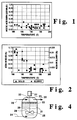
- the acetic acid solvent acid burn behavior relates to the oxidation of p-xylene to terephthalic acid in the evaporatively cooled process of the invention.
- Those skilled in the art will appreciate that the reaction of acetic acid solvent is undesired, and is found to be consistently low at typical reaction temperatures ranging from 180°C to 200°C.
- the indicated data was taken in a 3.3L LOR reactor modified in accordance with the invention.
- the inside diameter of the reactor was 12.7 cm (5 inches), and both a 5.08 cm (2 inch) impeller and a 7.62 cm (3 inch) impeller were positioned inside a draft tube and were used at a rotational speed of 1,000 rpm, said draft tube being positioned in the reactor as described and claimed herein.
- the feed mix was typically 11% p-xylene.
- the reaction catalysts employed were cobalt and manganese, as acetate salts, ranging in concentrations of from 200 to 2,000 ppm, and from 500 to 3,000 ppm, respectively. Bromine, in the form of hydrogen bromide, was used as an indicator with concentrations in the feed mix ranging from 400 to 3,000 rpm.
- Fig. 2 of the drawings illustrates the concentration of 4-CBA in the solid and slurry products of p-xylene oxidation with pure oxygen, as a function of temperature in the evaporatively cooled process of the invention. It will be seen that, in both the slurry and the solid product, the undesired concentration of 4-CBA decreases as the temperature increases into the desirable temperature conditions of the invention.
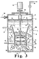
- Fig. 3 of the drawings illustrates a modified LOR system suitable for use in accordance with the invention for the oxidation of p-xylene with pure or nearly pure oxygen, using evaporative cooling of the reaction mixture.
- reactor vessel 1 has a body of organic liquid 2 therein, with gas-liquid interface 3 and overhead gas phase 4.
- Product liquid is removed from reactor vessel 1 through line 5.
- hollow draft tube 6 is typically centrally positioned within reactor vessel 1, with open end 7 at the top and open end 8 at the bottom thereof.
- Impeller means 9 are positioned within hollow draft tube 6.
- Impeller means 9 are downward pumping helical impeller means adapted to facilitate the downward flow of liquid at high velocity from said body of liquid 2 in hollow draft tube 6, the formation of turbulent roll cells B, and upward flow of said liquid therefrom in the annulus between the side wall of the reactor vessel and the outside of hollow draft tube 6 above said roll cells B.
- Impeller means 9 commonly include radial flow impeller means 10 and, if desired, lower baffle means 11 to facilitate the desired recirculating flow of liquid in reactor vessel 1.
- a suitable drive shaft 12 that extends upward from reactor vessel 1 for connection to suitable driving means 13 used to operate impeller means 9.
- hollow draft chamber 29 optimally includes a conically flared portion 30a at the upper end thereof for purposes of facilitating the flow of a gas bubble-liquid mixture into the draft chamber for downward passage therein.
- a conically flared portion is likewise positioned at the upper end of the hollow draft tube 6, but the configuration of said conically flared portion is quite different than that of Litz et al., and it is used for the opposite purpose of reducing the amount of gas bubbles drawn downward into hollow draft tube 6.
- vertically elongated, conically flared portion 6a of hollow draft tube 6 extends upward above the generally cylindrical bottom portion 6b thereof in which impeller means 9 is positioned.
- the increase in diameter at the top of said conically flared portion 6a serves to minimize the downward velocity of liquid flow pattern A across the top of said hollow draft tube 6, thereby appreciably reducing the portion of the gas bubbles rising in the reactor vessel outside said hollow draft tube 6 that are drawn down into impeller means 9 with the downward flow of reactant liquid in hollow draft tube 6.
- vertically elongated, conically flared upper portion 6a extends in vertical distance from 0% to 200%, preferably 100% to 150%, of the length of the bottom portion 6b of said hollow draft tube, in which impeller means 9 are positioned, and which is typically of cylindrical, nontapered configuration.
- the diameter at the top of said draft tube i.e., the enlarged diameter at the top of upper portion 6a, is appropriately sized to minimize the downward velocity of liquid across the top of the draft tube, e.g., to about 0.46 m/s (1.5 ft./sec.) in certain embodiments.
- the dimensions of said upper portion 6a of draft tube 6 will be understood to vary depending on the overall circumstances of a given application, a clearance of from 0.5 to 4.0 times the diameter of the draft tube will typically pertain between said upper portion 6a and the walls of the reaction vessel.
- the enlarged diameter of upper portion 6a will be from 1.5 to 3.0 times the diameter of hollow portion 6b.
- the enlarged diameter at the top of upper portion 6a will be from 40% to 80% of the inside diameter or width of reactor vessel 1, preferably from 50% to 60% thereof.
- the geometry and rotational speed of the impeller means are factors in determining the size of draft tube 6, and upper portion 6a thereof, for a particular application.
- the high velocity of the liquid pumped downward through the impeller means will typically be in the range 1.52 or 1.83 m/s (5 or 6 ft./sec.) to about 2.44 m/s (8 ft./sec.) or more, such as to create the high turbulent rolls cells that trap undissolved oxygen and enhance the desired dissolution thereof.
- Baffle means 6' is also desirably positioned in said conically flared portion 6a of hollow draft tube 6 to facilitate the downward flow of liquid to impeller means 9.
- the modified LOR impeller/draft tube combination of the invention effectively reduces the amount of recirculated gas passing downward in the draft tube.
- the gas bubbles passing upward in liquid flow pattern B in the reaction vessel outside bottom portion 6b of the hollow draft tube comprise principally volatile organic chemicals (VOCs), reactant solvent, water vapor and by products, such as CO and C0 2 , with only small amounts of undissolved oxygen being present therein.
- VOCs principally volatile organic chemicals
- the evaporation of the volatile organic species provide the evaporative cooling needed to remove the heat of reaction of the desired organic chemical oxidation operation.
- the lower nonflared portion 6b of hollow draft tube 6 is desirably positioned in the lower half of reactor vessel 1, as shown in Fig. 3, preferably near the bottom of said vessel so as to provide impact between the gas bubble-liquid mixture being discharged from the bottom of reactor vessel 1 and the bottom of the reactor vessel.
- baffle means corresponding to guide baffle means 34, used in the Litz et al. system to direct a gas bubble-liquid mixture to the top of hollow draft chamber 29, are not employed in the practice of the invention.
- the invention does, however, employ a small horizontal baffle means, i.e. disc 15, positioned in hollow draft tube 6 around drive shaft 12 in the region above the impeller means.
- Such baffle means serve to preclude the ingestion of gas, by vorex action, from overhead gas phase 4 along said drive shaft 12.
- the invention uses pure or nearly pure oxygen for the oxidation of p-xylene, with evaporative cooling being employed to remove the heat of reaction generated by the oxidation reaction.
- the mass transfer of oxygen from the gas phase to the liquid phase is substantially enhanced so as to increase the overall rate of reaction as compared to air based oxidation reactions.
- the practice of the invention enables a rapid rate of oxygen consumption to be achieved such that a very high oxygen use efficiency, i.e., at least 75% and preferably 90% or more, is obtained upon first injection of pure or nearly pure oxygen directly into hollow draft tube 6 as herein described.
- Such pure oxygen utilization coupled with the configuration of said hollow draft tube 6 as described above, minimizes the recirculation of gas bubbles through said draft tube 6, enables evaporative cooling to be advantageously employed, and precludes undesired cavitation in impeller means 9 that would impede or preclude the desired recirculation of liquid reactant and the breaking up and rapid dispersion of oxygen as fine bubbles in the liquid reactant.
- the pure or nearly pure oxygen feed is added to reactor vessel 1 at a point of high turbulence within hollow draft tube 6 rather than elsewhere in the body of organic liquid 2.
- oxygen addition can be made at any convenient point of high turbulence in said hollow draft tube 6, or just below it, such as, for example, through injection line 16 directly to lower portion 6b thereof immediately above impeller means 9, it is desirable and convenient to inject oxygen into the system, through injection line 17 to a point in said lower portion 6b below helical impeller means 9 and radial flow impeller means 10, such as flat blade turbines, if employed, or to a point in said lower portion 6b between helical impeller means 9 and said radial flow impeller means 10, if employed.
- nitrogen or other inert purge gas can be passed into overhead gas phase 4 through line 18 principally to inert the small amounts of unreacted oxygen that may escape into the overhead gas phase.
- the draft tube configuration is an excellent pump, which sets up the above-indicated roll cells that trap undissolved oxygen, which allows high oxygen efficiency to be achieved and limits the amount of nitrogen or other inert purge gas required in the overhead gas phase compared to the Fig. 4 embodiment discussed below.
- the roll cells form a very significant portion of the turbulent flow field produced by said impeller means.
- vent gases are desirably cooled, and the condensibles therefrom are returned to the reactor in preferred embodiments of the invention.
- a portion of the vent flow is desirably diverted for gas analysis of carbon dioxides and oxygen.
- the oxygen utilization efficiency observed in the practice of the invention for the reaction of p-xylene with oxygen is greater than 99%. That is, less than 1% of the oxygen that is fed to the reactor is vented unreacted.
- the solvent:reactant ratio is from 1:1 to 8:1 on a wt/volume basis in the practice of the invention.
- the catalyst for the desired oxidation reaction is a mixture of cobalt and manganese, preferably as acetate salts.
- the catalyst loading should be between 500 and 3,000 ppm, with the ratio of cobalt to manganese being from 0.1 to 10:1, preferably 3:1 on a weight basis.
- Bromine is used as an initiator and is added conveniently as hydrogen bromide (HBr).
- the bromine loading is between 0.1:1 and 1:1 on a weight basis relative to the total catalyst loading, preferably 0.3:1.
- the residence time for the liquid is between 30 and 90 minutes.
- the operating temperature is generally between 150°C and 200°C.
- the operating pressure is between 791 kPa (100 psig) and 1480 kPa (200 psig).
- Figs. 1 and 2 show the affect of operating temperature on acetic acid burn.
- Fig. 2 shows the affect of operating temperature on the concentration of 4-CBA in the product. As noted above, as the level of 4-CBA increases, product quality decreases. Based on the data shown in Figs.
- the preferred operating temperature for the practice of the invention has been found to be 180°C, with the preferred operating pressure being between 130 1028 kPa (psig) and 150 1186 kPa (psig).
- psig kPa
- psig kPa
- the relative flow rates for major components of the subject oxidation reaction are as follows with the flows being based on 100 lb./minute liquid feed.
- the liquid feed introduced to the reactor comprises 20 lb p-xylene, 70 lb. acetic acid, 10 lb. water, 0.22 lb. cobalt acetate, 0.08 lb. manganese acetate and 0.02 lb. hydrobromic acid.
- An oxygen feed of 18.5 lb. provides a liquid product stream of 69 lb. acetic acid, 30.5 lb. terephthalic acid, 17.5 lb. water, 0.22 lb.
- cobalt acetate 0.08 lb. manganese acetate, 0.02 lb. hydrobromic acid and 0.08 lb. xylene.
- a 2 lb. nitrogen purge gas us used, with the vent gas being 2 lb. nitrogen, 1.20 lb carbon dioxide, 0.60 lb. carbon monoxide and 0.23 lb. oxygen.
- the undesired production of methyl acetate in the conventional air based TPA production process is reported to be approximately 0.4/100 lb. of TPA produced.
- such methyl acetate production can be decreased very appreciably, with test data indicating that the methyl acetate production can be decreased to less than 0.2lb./100 lb. of TPA production in particular embodiments of the invention.
- Production of carbon monoxide and carbon dioxide can likewise be cut by nearly an order of magnitude in the practice of the invention.
- a similar decrease in the undesired production of the environmentally sensitive byproduct, methyl bromide can likewise be expected in the practice of the invention.
- reactor vessel 20 containing a body of liquid reactant 21, with gas-liquid interface 22 and overhead gas phase 23, has oxygen injected therein through line 24.
- Agitation means 25, driven by drive shaft 26 and drive motor 27, is used to disperse the oxygen in the form of bubbles 28 in said body of liquid reactant 21.
- Nitrogen or other inert vent gas is introduced into overhead gas phase 23 through line 29, and vent gas is withdrawn therefrom through line 30.
- pure oxygen or an oxygen-rich gas is injected directly into the recirculating portion of the body of liquid at an oxygen injection point or points near the impeller means.
- a position near the impeller means is one within the turbulent flow field produced by the impeller means, including the impeller suction and discharge flow fields.
- the turbulent flow field also significantly includes the roll cells, i.e. roll cells B in Fig. 3, formed in the reactor vessel below the hollow draft tube and said impeller means.
- the invention provides a significant advance in the field of TPA production.
- the highly effective LOR system is desirably modified for use without cavitation, enabling the desirable LOR gas-liquid mixing process and system to be employed with evaporative cooling.
- the practice of the invention enable the LOR process and system to be extended effectively to the oxidation of p-xylene to product TPA solid product
- the use of pure or nearly pure oxygen in the practice of the invention enables reaction conditions to be employed such as to reduce undesired byproduct formation, and to reduce solvent consumption and gas throughput in the reaction system and waste gas generation.
- the evaporative cooling feature of the invention offers significant and unexpected benefits in the increased reduction of liquid reactant and solvent consumption. By enabling by-product and waste generation to be reduced, while enhancing oxygen utilization and enabling milder operating conditions to be employed, the invention provides highly desirable technical, economic and environmental advantage over conventional TPA production operations.
Landscapes
- Chemical & Material Sciences (AREA)
- Organic Chemistry (AREA)
- Chemical Kinetics & Catalysis (AREA)
- Engineering & Computer Science (AREA)
- Oil, Petroleum & Natural Gas (AREA)
- Organic Low-Molecular-Weight Compounds And Preparation Thereof (AREA)
- Physical Or Chemical Processes And Apparatus (AREA)
Applications Claiming Priority (2)
| Application Number | Priority Date | Filing Date | Title |
|---|---|---|---|
| US241438 | 1994-05-11 | ||
| US08/241,438 US5523474A (en) | 1994-05-11 | 1994-05-11 | Terephthalic acid production using evaporative cooling |
Publications (2)
| Publication Number | Publication Date |
|---|---|
| EP0682005A1 EP0682005A1 (en) | 1995-11-15 |
| EP0682005B1 true EP0682005B1 (en) | 1999-09-01 |
Family
ID=22910704
Family Applications (1)
| Application Number | Title | Priority Date | Filing Date |
|---|---|---|---|
| EP95107044A Expired - Lifetime EP0682005B1 (en) | 1994-05-11 | 1995-05-10 | Terephthalic acid production using evaporative cooling |
Country Status (11)
| Country | Link |
|---|---|
| US (1) | US5523474A (ja) |
| EP (1) | EP0682005B1 (ja) |
| JP (1) | JP3100309B2 (ja) |
| KR (1) | KR100213583B1 (ja) |
| CN (1) | CN1064670C (ja) |
| BR (1) | BR9501992A (ja) |
| CA (1) | CA2149059C (ja) |
| DE (1) | DE69511756T2 (ja) |
| ES (1) | ES2135624T3 (ja) |
| RU (1) | RU2114818C1 (ja) |
| TW (1) | TW367323B (ja) |
Cited By (4)
| Publication number | Priority date | Publication date | Assignee | Title |
|---|---|---|---|---|
| US6649773B2 (en) | 2002-03-22 | 2003-11-18 | General Electric Company | Method for the manufacture of halophthalic acids and anhydrides |
| US6657067B2 (en) | 2002-03-22 | 2003-12-02 | General Electric Company | Method for the manufacture of chlorophthalic anhydride |
| US6657068B2 (en) | 2002-03-22 | 2003-12-02 | General Electric Company | Liquid phase oxidation of halogenated ortho-xylenes |
| US7732559B2 (en) | 2004-06-30 | 2010-06-08 | Sabic Innovative Plastics Ip B.V. | Method of making halophthalic acids and halophthalic anhydrides |
Families Citing this family (48)
| Publication number | Priority date | Publication date | Assignee | Title |
|---|---|---|---|---|
| US5696285A (en) * | 1995-12-29 | 1997-12-09 | Praxair Technology, Inc. | Production of terephthalic acid with excellent optical properties through the use of pure or nearly pure oxygen as the oxidant in p-xylene oxidation |
| ID16017A (id) * | 1996-02-27 | 1997-08-28 | Praxair Technology Inc | Proses yang dimanfaatkan untuk memproduksi asam organik |
| MX9702157A (es) * | 1996-03-22 | 1998-04-30 | Praxair Technology Inc | Optimizacion de contenido de agua en la oxidacion basada en oxigeno de p-xileno. |
| US5780683A (en) * | 1996-09-11 | 1998-07-14 | Abb Lummus Global Inc. | Cyclohexane oxidation |
| DE19643648A1 (de) * | 1996-10-22 | 1998-04-23 | Basf Ag | Verfahren zur Umsetzung von Grignardverbindungen mit Carbonylverbindungen und anschließender Hydrolyse |
| ID19133A (id) * | 1996-12-12 | 1998-06-18 | Praxair Technology Inc | Pengisian oksigen langsung kedalam reaktor-reaktor ruang gelembung |
| US6362367B2 (en) | 1998-04-21 | 2002-03-26 | Union Carbide Chemicals & Plastics Technology Corp. | Preparation of organic acids |
| US6540725B1 (en) * | 1998-06-04 | 2003-04-01 | Biosense Webster, Inc. | Injection catheter with controllably extendable injection needle |
| US6153790A (en) * | 1998-12-01 | 2000-11-28 | Shell Oil Company | Method to produce aromatic dicarboxylic acids using cobalt and zirconium catalysts |
| KR20000041506A (ko) | 1998-12-22 | 2000-07-15 | 유현식 | 아로마틱폴리카본산의 제조방법 |
| US6194607B1 (en) | 1998-12-22 | 2001-02-27 | Samsung General Chemicals Co., Ltd. | Method of producing aromatic carboxylic acids by oxidizing alkyl aromatic hydrocarbons or partially oxidized intermediates thereof |
| US6180822B1 (en) | 1998-12-22 | 2001-01-30 | Samsung General Chemical Co., Ltd. | Method of producing aromatic carboxylic acids by oxidizing alkyl aromatic compounds or partially oxidized intermediates thereof with carbon dioxide containing gas |
| KR100374785B1 (ko) * | 2000-06-29 | 2003-03-04 | 학교법인 포항공과대학교 | 액상 산화 반응기 |
| DE10206168A1 (de) * | 2002-02-14 | 2003-08-21 | Guehring Joerg | Kupplung für mudular aufgebaute Werkzeughalterarme |
| KR100896516B1 (ko) * | 2002-09-16 | 2009-05-08 | 에스케이케미칼주식회사 | 테레프탈산의 제조 방법 |
| US7273950B2 (en) * | 2003-06-13 | 2007-09-25 | Tereftalatos Mexicanos, S.A. De C.V. | Process and apparatus for the efficient oxidation of alkyl aromatic compounds |
| US20050256335A1 (en) * | 2004-05-12 | 2005-11-17 | Ovidiu Marin | Providing gases to aromatic carboxylic acid manufacturing processes |
| US7741515B2 (en) | 2004-09-02 | 2010-06-22 | Eastman Chemical Company | Optimized liquid-phase oxidation |
| US7692036B2 (en) * | 2004-11-29 | 2010-04-06 | Eastman Chemical Company | Optimized liquid-phase oxidation |
| US7608732B2 (en) * | 2005-03-08 | 2009-10-27 | Eastman Chemical Company | Optimized liquid-phase oxidation |
| US7482482B2 (en) * | 2004-09-02 | 2009-01-27 | Eastman Chemical Company | Optimized liquid-phase oxidation |
| US7399882B2 (en) * | 2004-09-02 | 2008-07-15 | Eastman Chemical Company | Optimized liquid-phase oxidation |
| US20060047153A1 (en) * | 2004-09-02 | 2006-03-02 | Wonders Alan G | Optimized liquid-phase oxidation |
| US7568361B2 (en) * | 2004-09-02 | 2009-08-04 | Eastman Chemical Company | Optimized liquid-phase oxidation |
| US7582793B2 (en) | 2004-09-02 | 2009-09-01 | Eastman Chemical Company | Optimized liquid-phase oxidation |
| US7390921B2 (en) * | 2004-09-02 | 2008-06-24 | Eastman Chemical Company | Optimized liquid-phase oxidation |
| US7572936B2 (en) * | 2004-09-02 | 2009-08-11 | Eastman Chemical Company | Optimized liquid-phase oxidation |
| US7608733B2 (en) * | 2004-09-02 | 2009-10-27 | Eastman Chemical Company | Optimized liquid-phase oxidation |
| US7586000B2 (en) * | 2004-09-02 | 2009-09-08 | Eastman Chemical Company | Optimized liquid-phase oxidation |
| US7495125B2 (en) * | 2004-09-02 | 2009-02-24 | Eastman Chemical Company | Optimized liquid-phase oxidation |
| US7563926B2 (en) * | 2004-09-02 | 2009-07-21 | Eastman Chemical Company | Optimized liquid-phase oxidation |
| US7589231B2 (en) * | 2004-09-02 | 2009-09-15 | Eastman Chemical Company | Optimized liquid-phase oxidation |
| US7507857B2 (en) * | 2004-09-02 | 2009-03-24 | Eastman Chemical Company | Optimized liquid-phase oxidation |
| US7692037B2 (en) | 2004-09-02 | 2010-04-06 | Eastman Chemical Company | Optimized liquid-phase oxidation |
| US7381836B2 (en) * | 2004-09-02 | 2008-06-03 | Eastman Chemical Company | Optimized liquid-phase oxidation |
| US7572932B2 (en) * | 2004-09-02 | 2009-08-11 | Eastman Chemical Company | Optimized liquid-phase oxidation |
| US7371894B2 (en) * | 2004-09-02 | 2008-05-13 | Eastman Chemical Company | Optimized liquid-phase oxidation |
| US7361784B2 (en) * | 2004-09-02 | 2008-04-22 | Eastman Chemical Company | Optimized liquid-phase oxidation |
| US7910769B2 (en) * | 2004-09-02 | 2011-03-22 | Eastman Chemical Company | Optimized liquid-phase oxidation |
| US7683210B2 (en) * | 2004-09-02 | 2010-03-23 | Eastman Chemical Company | Optimized liquid-phase oxidation |
| US7504535B2 (en) * | 2004-09-02 | 2009-03-17 | Eastman Chemical Company | Optimized liquid-phase oxidation |
| US7550627B2 (en) * | 2005-03-08 | 2009-06-23 | Eastman Chemical Company | Processes for producing aromatic dicarboxylic acids |
| US20060205974A1 (en) * | 2005-03-08 | 2006-09-14 | Lavoie Gino G | Processes for producing aromatic dicarboxylic acids |
| US7884232B2 (en) * | 2005-06-16 | 2011-02-08 | Eastman Chemical Company | Optimized liquid-phase oxidation |
| US7355068B2 (en) * | 2006-01-04 | 2008-04-08 | Eastman Chemical Company | Oxidation system with internal secondary reactor |
| WO2008136542A1 (en) * | 2007-05-02 | 2008-11-13 | Korea Institute Of Industrial Technology | Reactor for separating aluminium from multi-layer film materials |
| CN107335367A (zh) * | 2017-09-07 | 2017-11-10 | 深圳欧威奇科技有限公司 | 臭氧油混合罐 |
| CN111217671A (zh) * | 2018-11-23 | 2020-06-02 | 南京延长反应技术研究院有限公司 | 一种甲基芳烃氧化反应系统及其使用方法 |
Citations (1)
| Publication number | Priority date | Publication date | Assignee | Title |
|---|---|---|---|---|
| US4900480A (en) * | 1986-10-21 | 1990-02-13 | Union Carbide Corporation | Gas-liquid mixing |
Family Cites Families (8)
| Publication number | Priority date | Publication date | Assignee | Title |
|---|---|---|---|---|
| JPS5278846A (en) * | 1975-12-25 | 1977-07-02 | Matsuyama Sekyu Kagaku Kk | Continuous production of high purity telephthalic acid |
| JPS54109939A (en) * | 1978-02-15 | 1979-08-29 | Mitsui Petrochem Ind Ltd | Oxidation reactor for preparing aromatic carboxylic acid |
| US4454077A (en) * | 1982-07-08 | 1984-06-12 | Union Carbide Corporation | Process and apparatus for mixing a gas and a liquid |
| JPH078821B2 (ja) * | 1986-09-26 | 1995-02-01 | 三井石油化学工業株式会社 | 芳香族カルボン酸の製造方法 |
| US4855492A (en) * | 1988-05-27 | 1989-08-08 | Amoco Corporation | Process for production of aromatic polycarboxylic acids |
| US5004830A (en) * | 1989-11-29 | 1991-04-02 | Amoco Corporation | Process for oxidation of alkyl aromatic compounds |
| US5004571A (en) * | 1990-03-30 | 1991-04-02 | Union Carbide Industrial Gases Technology Corporation | Liquid level control in gas-liquid mixing operations |
| US5371283A (en) * | 1993-12-22 | 1994-12-06 | Praxair Technology, Inc. | Terephthalic acid production |
-
1994
- 1994-05-11 US US08/241,438 patent/US5523474A/en not_active Expired - Fee Related
-
1995
- 1995-04-24 TW TW084104012A patent/TW367323B/zh active
- 1995-05-10 CN CN95105714A patent/CN1064670C/zh not_active Expired - Fee Related
- 1995-05-10 EP EP95107044A patent/EP0682005B1/en not_active Expired - Lifetime
- 1995-05-10 ES ES95107044T patent/ES2135624T3/es not_active Expired - Lifetime
- 1995-05-10 BR BR9501992A patent/BR9501992A/pt not_active Application Discontinuation
- 1995-05-10 JP JP07135768A patent/JP3100309B2/ja not_active Expired - Fee Related
- 1995-05-10 CA CA002149059A patent/CA2149059C/en not_active Expired - Fee Related
- 1995-05-10 DE DE69511756T patent/DE69511756T2/de not_active Expired - Fee Related
- 1995-05-10 RU RU95107152A patent/RU2114818C1/ru active
- 1995-05-10 KR KR1019950011369A patent/KR100213583B1/ko not_active IP Right Cessation
Patent Citations (1)
| Publication number | Priority date | Publication date | Assignee | Title |
|---|---|---|---|---|
| US4900480A (en) * | 1986-10-21 | 1990-02-13 | Union Carbide Corporation | Gas-liquid mixing |
Cited By (4)
| Publication number | Priority date | Publication date | Assignee | Title |
|---|---|---|---|---|
| US6649773B2 (en) | 2002-03-22 | 2003-11-18 | General Electric Company | Method for the manufacture of halophthalic acids and anhydrides |
| US6657067B2 (en) | 2002-03-22 | 2003-12-02 | General Electric Company | Method for the manufacture of chlorophthalic anhydride |
| US6657068B2 (en) | 2002-03-22 | 2003-12-02 | General Electric Company | Liquid phase oxidation of halogenated ortho-xylenes |
| US7732559B2 (en) | 2004-06-30 | 2010-06-08 | Sabic Innovative Plastics Ip B.V. | Method of making halophthalic acids and halophthalic anhydrides |
Also Published As
| Publication number | Publication date |
|---|---|
| RU95107152A (ru) | 1997-02-10 |
| CA2149059C (en) | 2000-03-28 |
| ES2135624T3 (es) | 1999-11-01 |
| CA2149059A1 (en) | 1995-11-12 |
| RU2114818C1 (ru) | 1998-07-10 |
| DE69511756D1 (de) | 1999-10-07 |
| CN1114643A (zh) | 1996-01-10 |
| JPH0859547A (ja) | 1996-03-05 |
| KR100213583B1 (ko) | 1999-09-01 |
| CN1064670C (zh) | 2001-04-18 |
| DE69511756T2 (de) | 2000-03-09 |
| US5523474A (en) | 1996-06-04 |
| KR950032055A (ko) | 1995-12-20 |
| TW367323B (en) | 1999-08-21 |
| JP3100309B2 (ja) | 2000-10-16 |
| EP0682005A1 (en) | 1995-11-15 |
| BR9501992A (pt) | 1996-02-27 |
Similar Documents
| Publication | Publication Date | Title |
|---|---|---|
| EP0682005B1 (en) | Terephthalic acid production using evaporative cooling | |
| EP0781754B1 (en) | Process and apparatus for the oxidation of alhylaromatic compounds to aromatic carboxylic acids | |
| EP0682000B1 (en) | Enhanced oxidation of organic chemicals | |
| EP0659730B1 (en) | Terephthalic acid production | |
| EP1073621B1 (en) | Preparation of organic acids | |
| EP0264905B1 (en) | Process and apparatus for mixing of gases and liquids | |
| CA2278400C (en) | Improved reactor system | |
| EP0796837A1 (en) | Process for producingan aromatic carboxylic acid | |
| WO2017017524A1 (en) | Loop oxidation of toluene to benzoic acid | |
| MXPA00010181A (en) | Preparation of organic acids |
Legal Events
| Date | Code | Title | Description |
|---|---|---|---|
| PUAI | Public reference made under article 153(3) epc to a published international application that has entered the european phase |
Free format text: ORIGINAL CODE: 0009012 |
|
| AK | Designated contracting states |
Kind code of ref document: A1 Designated state(s): BE DE ES FR GB IT LU NL PT SE |
|
| 17P | Request for examination filed |
Effective date: 19951122 |
|
| 17Q | First examination report despatched |
Effective date: 19970610 |
|
| GRAG | Despatch of communication of intention to grant |
Free format text: ORIGINAL CODE: EPIDOS AGRA |
|
| GRAG | Despatch of communication of intention to grant |
Free format text: ORIGINAL CODE: EPIDOS AGRA |
|
| GRAG | Despatch of communication of intention to grant |
Free format text: ORIGINAL CODE: EPIDOS AGRA |
|
| GRAH | Despatch of communication of intention to grant a patent |
Free format text: ORIGINAL CODE: EPIDOS IGRA |
|
| GRAH | Despatch of communication of intention to grant a patent |
Free format text: ORIGINAL CODE: EPIDOS IGRA |
|
| GRAH | Despatch of communication of intention to grant a patent |
Free format text: ORIGINAL CODE: EPIDOS IGRA |
|
| GRAA | (expected) grant |
Free format text: ORIGINAL CODE: 0009210 |
|
| AK | Designated contracting states |
Kind code of ref document: B1 Designated state(s): BE DE ES FR GB IT LU NL PT SE |
|
| REF | Corresponds to: |
Ref document number: 69511756 Country of ref document: DE Date of ref document: 19991007 |
|
| REG | Reference to a national code |
Ref country code: ES Ref legal event code: FG2A Ref document number: 2135624 Country of ref document: ES Kind code of ref document: T3 |
|
| ET | Fr: translation filed | ||
| REG | Reference to a national code |
Ref country code: PT Ref legal event code: SC4A Free format text: AVAILABILITY OF NATIONAL TRANSLATION Effective date: 19991105 |
|
| PGFP | Annual fee paid to national office [announced via postgrant information from national office to epo] |
Ref country code: FR Payment date: 20000419 Year of fee payment: 6 |
|
| PGFP | Annual fee paid to national office [announced via postgrant information from national office to epo] |
Ref country code: SE Payment date: 20000420 Year of fee payment: 6 Ref country code: GB Payment date: 20000420 Year of fee payment: 6 |
|
| PGFP | Annual fee paid to national office [announced via postgrant information from national office to epo] |
Ref country code: NL Payment date: 20000427 Year of fee payment: 6 |
|
| PGFP | Annual fee paid to national office [announced via postgrant information from national office to epo] |
Ref country code: LU Payment date: 20000504 Year of fee payment: 6 |
|
| PGFP | Annual fee paid to national office [announced via postgrant information from national office to epo] |
Ref country code: PT Payment date: 20000509 Year of fee payment: 6 |
|
| PGFP | Annual fee paid to national office [announced via postgrant information from national office to epo] |
Ref country code: BE Payment date: 20000512 Year of fee payment: 6 |
|
| PGFP | Annual fee paid to national office [announced via postgrant information from national office to epo] |
Ref country code: ES Payment date: 20000608 Year of fee payment: 6 |
|
| PLBE | No opposition filed within time limit |
Free format text: ORIGINAL CODE: 0009261 |
|
| STAA | Information on the status of an ep patent application or granted ep patent |
Free format text: STATUS: NO OPPOSITION FILED WITHIN TIME LIMIT |
|
| 26N | No opposition filed | ||
| PG25 | Lapsed in a contracting state [announced via postgrant information from national office to epo] |
Ref country code: LU Free format text: LAPSE BECAUSE OF NON-PAYMENT OF DUE FEES Effective date: 20010510 Ref country code: GB Free format text: LAPSE BECAUSE OF NON-PAYMENT OF DUE FEES Effective date: 20010510 |
|
| PG25 | Lapsed in a contracting state [announced via postgrant information from national office to epo] |
Ref country code: SE Free format text: LAPSE BECAUSE OF NON-PAYMENT OF DUE FEES Effective date: 20010511 Ref country code: ES Free format text: LAPSE BECAUSE OF NON-PAYMENT OF DUE FEES Effective date: 20010511 |
|
| PG25 | Lapsed in a contracting state [announced via postgrant information from national office to epo] |
Ref country code: BE Free format text: LAPSE BECAUSE OF NON-PAYMENT OF DUE FEES Effective date: 20010531 |
|
| BERE | Be: lapsed |
Owner name: PRAXAIR TECHNOLOGY INC. Effective date: 20010531 |
|
| PG25 | Lapsed in a contracting state [announced via postgrant information from national office to epo] |
Ref country code: PT Free format text: LAPSE BECAUSE OF NON-PAYMENT OF DUE FEES Effective date: 20011130 |
|
| PG25 | Lapsed in a contracting state [announced via postgrant information from national office to epo] |
Ref country code: NL Free format text: LAPSE BECAUSE OF NON-PAYMENT OF DUE FEES Effective date: 20011201 |
|
| GBPC | Gb: european patent ceased through non-payment of renewal fee |
Effective date: 20010510 |
|
| PG25 | Lapsed in a contracting state [announced via postgrant information from national office to epo] |
Ref country code: FR Free format text: LAPSE BECAUSE OF NON-PAYMENT OF DUE FEES Effective date: 20020131 |
|
| NLV4 | Nl: lapsed or anulled due to non-payment of the annual fee |
Effective date: 20011201 |
|
| REG | Reference to a national code |
Ref country code: PT Ref legal event code: MM4A Free format text: LAPSE DUE TO NON-PAYMENT OF FEES Effective date: 20011130 |
|
| REG | Reference to a national code |
Ref country code: ES Ref legal event code: FD2A Effective date: 20030303 |
|
| PGFP | Annual fee paid to national office [announced via postgrant information from national office to epo] |
Ref country code: DE Payment date: 20030528 Year of fee payment: 9 |
|
| PG25 | Lapsed in a contracting state [announced via postgrant information from national office to epo] |
Ref country code: DE Free format text: LAPSE BECAUSE OF NON-PAYMENT OF DUE FEES Effective date: 20041201 |
|
| PG25 | Lapsed in a contracting state [announced via postgrant information from national office to epo] |
Ref country code: IT Free format text: LAPSE BECAUSE OF NON-PAYMENT OF DUE FEES;WARNING: LAPSES OF ITALIAN PATENTS WITH EFFECTIVE DATE BEFORE 2007 MAY HAVE OCCURRED AT ANY TIME BEFORE 2007. THE CORRECT EFFECTIVE DATE MAY BE DIFFERENT FROM THE ONE RECORDED. Effective date: 20050510 |