EP0681176A1 - Viscosimètre - Google Patents
Viscosimètre Download PDFInfo
- Publication number
- EP0681176A1 EP0681176A1 EP95201114A EP95201114A EP0681176A1 EP 0681176 A1 EP0681176 A1 EP 0681176A1 EP 95201114 A EP95201114 A EP 95201114A EP 95201114 A EP95201114 A EP 95201114A EP 0681176 A1 EP0681176 A1 EP 0681176A1
- Authority
- EP
- European Patent Office
- Prior art keywords
- oscillatory body
- magnetic field
- oscillatory
- constant magnetic
- oscillation
- Prior art date
- Legal status (The legal status is an assumption and is not a legal conclusion. Google has not performed a legal analysis and makes no representation as to the accuracy of the status listed.)
- Granted
Links
Images


Classifications
-
- G—PHYSICS
- G01—MEASURING; TESTING
- G01N—INVESTIGATING OR ANALYSING MATERIALS BY DETERMINING THEIR CHEMICAL OR PHYSICAL PROPERTIES
- G01N11/00—Investigating flow properties of materials, e.g. viscosity, plasticity; Analysing materials by determining flow properties
-
- G—PHYSICS
- G01—MEASURING; TESTING
- G01N—INVESTIGATING OR ANALYSING MATERIALS BY DETERMINING THEIR CHEMICAL OR PHYSICAL PROPERTIES
- G01N11/00—Investigating flow properties of materials, e.g. viscosity, plasticity; Analysing materials by determining flow properties
- G01N11/10—Investigating flow properties of materials, e.g. viscosity, plasticity; Analysing materials by determining flow properties by moving a body within the material
- G01N11/16—Investigating flow properties of materials, e.g. viscosity, plasticity; Analysing materials by determining flow properties by moving a body within the material by measuring damping effect upon oscillatory body
- G01N11/162—Oscillations being torsional, e.g. produced by rotating bodies
Definitions
- the invention relates to a viscometer provided with a transducer for converting a viscosity parameter of a fluid into an electrical signal, comprising a container, provided with a cavity intended for the fluid to be measured, a support element firmly connected to said container, an oscillatory device, which at one end is firmly attached to the support element and at the other end has an oscillatory body, and, in order to bring and maintain the oscillatory body in oscillation, an oscillation drive coil powered by alternating current and a constant magnetic field device for generating a constant magnetic field, and a detection device for detecting the oscillation of the oscillatory body.
- a viscometer of this type is disclosed in US Patent 4 005 599.
- the known transducer is of the torsion type and comprises a housing, to which a support element is firmly attached transversely to the side wall thereof.
- a torsion device is arranged in the housing, which device consists of an oscillatory body and torsion strips, which oscillatory body is connected at one end by means of the torsion strips to the support element. The other end of the oscillatory body is able to move freely.
- a permanent magnet is arranged in the oscillatory body, the field lines of said magnet running transversely to the side wall of the meter housing. At least at the location of the permanent magnet the housing is made of a non-magnetic material, so that the field lines of the permanent magnet extend outside the housing.
- An oscillation drive coil is positioned outside the meter housing at the height of the permanent magnet and at a small angle with respect to the North-South direction of the permanent magnet.
- a detection device which detects the oscillation of the oscillatory body, is present in the known viscometer.
- the viscosity parameter is determined from, inter alia, the detection result.
- the known device has the disadvantage that the iron particles from the fluid to be measured adhere to the oscillatory body and collect there, as a result of which an additional damping is caused. It has been found that only a small amount of adhering iron particles has a substantial effect on the measurement result. The consequence of this is that the viscometer has to be cleaned frequently. Moreover, as a result of the attractive effect of the permanent magnet, cleaning of the oscillatory body is not simple.
- the aim of the invention is to provide a viscometer of the type mentioned in the preamble with which the abovementioned problems are avoided and which is particularly easy to maintain.
- the constant magnetic field device is arranged such that said device remains out of contact with the fluid to be measured and the constant magnetic field lines generated by said device are directed towards the oscillatory body and in that the oscillation drive coil is accommodated in the oscillatory body with its centre line at a small angle with respect to the constant magnetic field lines.
- the constant magnetic field device consists of at least one permanent magnet which is positioned adjacent to the oscillatory body outside the cavity intended for the fluid to be measured. By removing the permanent magnet, the viscometer is easier to clean.
- the constant magnetic field device consists of at least one coil powered by a direct current, which coil is positioned adjacent to the oscillatory body outside the cavity intended for the fluid to be measured, with its centre line directed towards the oscillatory body.
- the detection device is an acceleration detector, the viscosity parameter being determined from the amplitude of the signal emitted by said detector and that of the signal applied to the oscillation drive coil.
- a feedback is used to maintain the torsional vibration of the oscillatory body, wherein the detection device, comprising a piezo-electric crystal, for detection of the oscillation of the oscillatory body is arranged at one end and the oscillation drive coil is arranged at the other end of the feedback loop.
- a further aim of the invention is further to simplify the viscometer.
- This simplification is achieved in that, in one embodiment of the invention, the acceleration detector is connected via a phase shifter to the oscillation drive coil. By this means the oscillation is automatically maintained with a very much simpler circuit.
- an amplitude measurement is used instead of a frequency measurement, as a result of which not only is simpler circuitry possible but it is also possible to measure with better resolution.
- the acceleration detector consists of two piezo-electric strips, which run parallel to one another and in a plane extending parallel to the oscillation direction of the oscillatory body, and one end of each strip being firmly attached to the oscillatory body, the points of attachment being located diametrically opposite one another, whilst the other ends thereof are able to move freely in the oscillation direction of the oscillatory body and face in opposing directions, and in that the outputs of the piezo-electric strips are connected to the respective inputs of an instrumentation amplifier, the output of which is connected to the phase shifter.
- phase shift is used for determining the frequency shift in function of the phase shift.
- a phase shift of 90 degrees is used for obtaining a control in the resonance frequency.
- control and detection are coupled to a rod not damped by the liquid.
- a tube arranged around the rod is subjected to the damping of the liquid.
- the viscometer according to US-A-4,905,499 cannot be used as flow-through sensor, because a separate mass is used for obtaining a vibration system. According to this invention, however, a sensor is achieved, in which the mass, the drive and the detection are located in the measuring head in order to realize a single mass-spring-system.
- the invention is based on the insight that a fluid has an effect, in particular a damping effect, on a vibrating oscillatory element which is immersed therein.
- a feedback system can be used to maintain the oscillatory element in mechanical vibration by supplying energy to the system to compensate for viscous and other inherent mechanical and electrical losses. This is achieved by means of amplifiers in the feedback system.
- the complex shear viscosity can be determined by measuring the resonance frequency of the oscillatory element and the damping thereof.
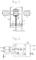
- the viscometer according to the invention is provided by way of an example with a transducer for converting a viscosity parameter of a fluid into an electrical signal.
- Said transducer comprises a meter housing 1 and a support element or baseplate 2 firmly connected thereto.
- An oscillatory device is supported by said baseplate 2, which oscillatory device consists of a torsion rod 3, which is rigidly attached to the baseplate 2 and perpendicular thereto, and an oscillatory body 4, which is formed by a cylindrical mass 4, which, in turn, is firmly connected at one end to the free end of the torsion rod 3.
- the combination of torsion rod 3 and cylindrical mass 4 is brought into and maintained in vibration in a torsion mode.
- an excitation system which comprises a magnet 5 and a drive coil 6.
- the drive coil 6 is accommodated in the cylindrical mass 4, whilst the magnet 5 is positioned outside the housing 1.
- the mutual orientation of the permanent magnet 5 and the drive coil 6 is such that the centre line of the drive coil is at a small angle with respect to the magnetic field lines of the permanent magnet.
- a second magnet 7 is used.
- the magnet or electromagnet 5 is arranged outside the housing 1, but said magnet can also be accommodated sunken completely or partly into the housing.
- this so-called sunken position of the magnet provision must preferably be made to ensure that the fluid can not come into contact with the magnet, in other words the magnet is located outside the cavity intended for the fluid to be measured and the magnet is thus separated from said cavity.
- a separated arrangement of the magnet is shown in Figs. 6 and 7.
- At least the cylindrical mass 4 of the oscillatory device is submerged in a fluid or liquid 8, which is present in the cavity which is delimited by the baseplate 2 and a wall, which, for example, is cylindrical, of the housing 1.
- This viscometer is suitable as a through-flow meter and the liquid to be measured can, for example, be fed in through openings 9 in the baseplate 2, can flow along the torsion rod 3 and the cylindrical mass 4 and can be discharged or reversed by the top opening in the housing 1.
- the housing 1, with the oscillatory body 4 accommodated therein, can be integrated in a pipe of a pipe system in order to measure a viscosity parameter of the fluid or liquid flowing through the pipe system, continuously or at any desired point in time. For a static measurement, the top opening of the housing can be closed.
- an excitation signal in the form of an alternating current is applied to the drive coil 6.
- Said excitation signal can, for example, be generated by a frequency generator.
- the frequency and magnitude of the excitation signal can be controlled by means of a microprocessor.
- the amplitude of the torsional vibration is measured by means of the detection device 11.
- the detection output signal from the detection device 11 is fed to the exterior via the output conductor 12 fed through the torsion rod 3.
- the detection signal is a measure of the viscosity of the liquid in which the cylindrical mass is submerged and can be amplified, in a manner which is not shown, filtered by means of a bandpass filter and fed to a voltmeter which is read by the microprocessor.
- the permanent magnets 5 and 7 are shown as electromagnets, to the coil of which a direct current signal has to be applied.
- the advantage of the viscometer according to Fig. 1 is that this viscometer is particularly easy to maintain because the frequency of cleaning is very much lower than in the case of known systems in which the permanent magnet is accommodated in the oscillatory body 4, as a result of which iron particles or other magnetic impurities collect on the oscillatory body. Furthermore, the viscometer can be cleaned easily by removing the permanent magnet 5 or switching off the direct current signal applied to the coil of the permanent electromagnet. The iron particles which have collected can then be removed easily by means of cleaning fluid unhindered by magnetic attraction. Consequently, the viscometer is particularly suitable for integration in a pipe system, because the viscometer does not have to be detached from the system in order to remove the oscillatory body 4 therefrom and clean it separately.
- a cleaning fluid can be fed through the housing 1 of the viscometer without removing the latter from the system.
- both the alternating current signal fed to the supply conductor 10 and the direct current signal applied to the coil of the permanent electromagnet can be switched off. It has been found that cleaning can then take place particularly simply and thoroughly.
- the minimum distance between the side surface of the cylindrical mass 4 and the wall of the housing 1 is determined by the requirement that the shear wave must have virtually died away when this reaches the wall 13.
- the amplitude of the shear wave is attenuated by a factor of 1000 over a distance of 2 mm at a viscosity of 100 mPa and a frequency of 400 Hz.
- FIGs 2, 3 and 4 show an oscillatory body according to an embodiment of the invention.
- the oscillatory body 4 is produced from a non-magnetic or non-magnetisable material.
- a very suitable material is stainless steel of austenitic structure, such as stainless steel 316. In some applications, a plastic could be adequate.
- the oscillatory body 4 is closed at the top and bottom.
- One end of the torsion rod 3 is firmly connected to the bottom closure 15, the other end of said torsion rod being firmly connected to the baseplate 2.
- the detection device 11 is firmly attached to the housing above the bottom closure 15, as is the drive coil 6 by means of the screws 13 and 14 (Figs 2 and 3).
- the detection device 11 is an acceleration detector.
- An embodiment of the acceleration detector which is preferably to be used can be seen more clearly in Fig. 4.
- Said acceleration detector comprises two supports 16, 17, which are firmly attached to the oscillatory body.
- Said supports 16 and 17 support the respective piezo-electric strips 18 and 19 on one side. The other ends of the strips 18 and 19 are able to move freely and are provided with weights 20 and 21 respectively.
- an electric feedback circuit can be connected between the drive coil 6 and the detection device consisting of the piezo-electric strips 18 and 19, as a result of which the oscillation in the torsion mode of the oscillatory device is automatically maintained, it being possible to determine the viscosity of the fluid or liquid to be measured from the ratio of the amplitude of the detection signal to that of the excitation signal applied to the drive coil 6 by means of, for example, a microprocessor.
- Said feedback circuit in the measuring circuit of the viscometer according to the invention is shown in Fig. 5.
- the piezo-electric strips 18 and 19 are shown diagrammatically as piezo elements and indicated by P1 and P2.
- the piezo elements P1 and P2 are connected via parallel resistors R1 and R2 to an instrumentation amplifier IA.
- the polarities are indicated here.
- the feedback circuit consists of the said instrumentation amplifier IA, the filter F1, the phase shifter FD, the automatic gain controller AGC and the amplifier V1.
- the drive coil 6 is connected to the output of the amplifier V1.
- the oscillatory body 4 shown in Figures 1, 2, 3 and 4 is brought into and held in vibration in the torsion mode.
- the signal which appears at the output of the phase shifter FD and the signal at the junction between the amplifier V1 and the automatic gain controller AGC are fed to the inputs I2 and I3, respectively, of the microprocessor ⁇ P, which, on the basis of the ratio of the amplitude of the said signals derives a viscosity output signal which is passed to the output 02.
- the signal which originates from a temperature sensor, which is not shown and is arranged in the vicinity of the oscillatory body, is fed to the amplifier V2, the output signal from which is fed to the input I1 of the microprocessor ⁇ P.
- a temperature signal appears at the output 01 of the microprocessor.
- the signal originating from the temperature sensor can be used by the microprocessor ⁇ P to effect a temperature compensation.
- the moment of inertia of the baseplate 2 is chosen to be large compared with the moment of inertia of the torsion mass.
- All construction materials in the vicinity of the magnets 5 and 7 are made of non-magnetisable material, such as austenitic stainless steel, for example stainless steel 316, or plastic. Furthermore, preferably materials are chosen which have as low a conductivity as possible, so that the damping of the oscillatory mass as a consequence of eddy current effects is as small as possible.
- a significant advantage of the above-described design of the transducer for the viscometer is the very low temperature dependence of the resonance frequency of the oscillatory device, so that, by means of the measured temperature, the microprocessor is easily able to carry out the temperature compensation.
- the electrical part of the viscometer is very simple and comprises only a small number of components.
- the most important advantage of the viscometer according to the invention is that it is very easy to maintain (low cleaning frequency) and that the viscometer does not have to be removed from the integrated system in order to clean the interior of the housing and the oscillatory body.
- the viscometer according to the invention has the advantage that the translation of the oscillatory body is compensated.
- Figures 6 and 7 show an embodiment of the invention in which the viscometer according to the invention is integrated in a pipe bend or knee 22, which is provided with fixing flanges 23 and 24 for installing the pipe bend 22 in a pipeline system.
- the bend 22 has been cut open at the location of the viscometer.
- the oscillatory body 4 is connected via the torsion rod 3 to the base 2.
- the torsion rod 3 and the base 2 are hollow for feeding through the supply and return wires for the drive coil accommodated in the oscillatory body 4 and the piezo-electric strips.
- the base 2 is firmly connected by means of the blanking element 25 to the bend 22.
- the blanking element 25 is accommodated in the bore 26 of the bend 22 and is screwed firmly to the flanges delimiting said opening by means of the screw 27.
- the base 2 is accommodated in the central bore 28 of the blanking element 25 and is held firmly therein by the retaining nut 29.
- the supply and return wires issuing from the base 2 run to the electronic circuit of the viscometer incorporated in the housing 31.
- the housing 31 is screwed by means of a cylindrical connecting piece 32, provided with flanges, by means of the screw 33 and the screw 34 to the blanking element 25.
- a temperature sensor 35 is also fixed in the blanking element 25 and connected by means of the connecting wire 36 to the associated circuit accommodated in the housing 31 (see Fig. 7).
- FIG. 6 One of the electromagnets 5, 7 arranged adjacent to the oscillatory body 4 on either side can be seen most clearly in Fig. 6.
- the core 37 of magnetisable material and the associated coil 38 of the electromagnet 5 are accommodated in the housing 39, which components are detachably fixed as a unit in the bore 40 of the housing 39. Fixing is by means of the cap 41 with the associated screws 42.
- the connecting wires of the direct current coil are fed by means of the protective tube 43 to the associated power supply in the housing 31.
Landscapes
- Physics & Mathematics (AREA)
- Health & Medical Sciences (AREA)
- Life Sciences & Earth Sciences (AREA)
- Chemical & Material Sciences (AREA)
- Analytical Chemistry (AREA)
- Biochemistry (AREA)
- General Health & Medical Sciences (AREA)
- General Physics & Mathematics (AREA)
- Immunology (AREA)
- Pathology (AREA)
- Measuring Volume Flow (AREA)
- Combined Devices Of Dampers And Springs (AREA)
- Measurement Of Mechanical Vibrations Or Ultrasonic Waves (AREA)
- Pharmaceuticals Containing Other Organic And Inorganic Compounds (AREA)
- Transmission And Conversion Of Sensor Element Output (AREA)
Applications Claiming Priority (2)
| Application Number | Priority Date | Filing Date | Title |
|---|---|---|---|
| NL9400723A NL9400723A (nl) | 1994-05-02 | 1994-05-02 | Viscositeitsmeter. |
| NL9400723 | 1994-05-02 |
Publications (2)
| Publication Number | Publication Date |
|---|---|
| EP0681176A1 true EP0681176A1 (fr) | 1995-11-08 |
| EP0681176B1 EP0681176B1 (fr) | 2003-05-21 |
Family
ID=19864149
Family Applications (1)
| Application Number | Title | Priority Date | Filing Date |
|---|---|---|---|
| EP95201114A Expired - Lifetime EP0681176B1 (fr) | 1994-05-02 | 1995-04-28 | Viscosimètre |
Country Status (14)
| Country | Link |
|---|---|
| US (1) | US5698773A (fr) |
| EP (1) | EP0681176B1 (fr) |
| JP (1) | JP3537910B2 (fr) |
| KR (1) | KR100347406B1 (fr) |
| CN (1) | CN1125327C (fr) |
| CA (1) | CA2148388C (fr) |
| DE (1) | DE69530815T2 (fr) |
| DK (1) | DK0681176T3 (fr) |
| ES (1) | ES2199973T3 (fr) |
| FI (1) | FI115252B (fr) |
| NL (1) | NL9400723A (fr) |
| NO (1) | NO315585B1 (fr) |
| PL (1) | PL177239B1 (fr) |
| RU (1) | RU2152606C1 (fr) |
Cited By (4)
| Publication number | Priority date | Publication date | Assignee | Title |
|---|---|---|---|---|
| NL1010308C2 (nl) * | 1998-10-13 | 2000-04-17 | Vaf Instr Bv | Piëzo-elektrische viscositeitsmeter. |
| FR2921726A1 (fr) * | 2007-10-02 | 2009-04-03 | Fr De Services Sa Soc | Procede et systeme pour la determination de la viscosite d'un produit |
| FR3015676A1 (fr) * | 2013-12-24 | 2015-06-26 | Sofraser | Systeme et procede de mesure en ligne de la viscosite d'un produit |
| US9074981B2 (en) | 2009-08-27 | 2015-07-07 | Johannes Kepler Universitaet | Sensor arrangement for measuring properties of fluids |
Families Citing this family (19)
| Publication number | Priority date | Publication date | Assignee | Title |
|---|---|---|---|---|
| US7775976B2 (en) * | 1920-03-19 | 2010-08-17 | Alere Switzerland Gmbh | Method to determine a coagulation property of a fluid |
| US6311549B1 (en) | 1999-09-23 | 2001-11-06 | U T Battelle Llc | Micromechanical transient sensor for measuring viscosity and density of a fluid |
| US6484587B2 (en) * | 2000-02-07 | 2002-11-26 | Mamac Systems, Inc. | Pressure sensor |
| JP3348162B2 (ja) * | 2000-05-09 | 2002-11-20 | シービーシーマテリアルズ株式会社 | 液体の粘性測定法と粘弾性測定法並びに粘弾性測定装置 |
| DE10131429A1 (de) * | 2001-06-29 | 2003-01-16 | Bosch Gmbh Robert | Vorrichtung zur Auswertung des Signals eines Viskositätssensors |
| US7614285B2 (en) * | 2007-03-27 | 2009-11-10 | Cambridge Viscosity, Inc. | Dynamic reciprocating-bob rheometry |
| WO2012033772A2 (fr) * | 2010-09-07 | 2012-03-15 | Sayir, Mahir | Dispositif de mesure de propriétés de fluide ayant un résonateur symétrique |
| BR112015004028A2 (pt) * | 2012-08-31 | 2017-07-04 | Halliburton Energy Services Inc | aparelho e método para determinar viscosidade do fluido em um ambiente no fundo de furo |
| US10443378B2 (en) | 2012-08-31 | 2019-10-15 | Halliburton Energy Services, Inc. | Apparatus and method for downhole in-situ determination of fluid viscosity |
| US9562840B2 (en) | 2014-12-03 | 2017-02-07 | Cambridge Viscosity, Inc. | High precision reciprocating bob viscometer |
| WO2016109447A1 (fr) | 2014-12-29 | 2016-07-07 | Concentric Meter Corporation | Capteur et dispositif de mesure de paramètre de fluide |
| US10126266B2 (en) | 2014-12-29 | 2018-11-13 | Concentric Meter Corporation | Fluid parameter sensor and meter |
| WO2016109451A1 (fr) | 2014-12-29 | 2016-07-07 | Concentric Meter Corporation | Transducteur électromagnétique |
| RU2608574C1 (ru) * | 2015-09-14 | 2017-01-23 | Федеральное государственное бюджетное образовательное учреждение высшего образования "Кемеровский технологический институт пищевой промышленности (университет)" | Вибрационный реометр |
| CN108104808A (zh) * | 2018-01-05 | 2018-06-01 | 中国海洋石油集团有限公司 | 井下流体粘度测量短节 |
| US10855158B2 (en) * | 2018-04-19 | 2020-12-01 | Watasensor, Inc. | Magnetic power generation |
| RU189049U1 (ru) * | 2019-01-09 | 2019-05-07 | Федеральное государственное казенное военное образовательное учреждение высшего образования "Военный учебно-научный центр Военно-воздушных сил "Военно-воздушная академия имени профессора Н.Е. Жуковского и Ю.А. Гагарина" (г. Воронеж) Министерства обороны Российской Федерации | Устройство для измерения вязкости моторного масла и контроля его работоспособности |
| US11162861B2 (en) * | 2019-04-24 | 2021-11-02 | Lawrence Livermore National Security, Llc | Magnetically coupled pressure sensor |
| KR20200144734A (ko) | 2019-06-19 | 2020-12-30 | 조남섭 | 선박 엔진 연료의 점도감지장치 및 그 장치의 구동방법 |
Citations (5)
| Publication number | Priority date | Publication date | Assignee | Title |
|---|---|---|---|---|
| US4005599A (en) * | 1975-08-05 | 1977-02-01 | International Telephone And Telegraph Corporation | Fluid property detection system |
| EP0297032A1 (fr) * | 1987-06-12 | 1988-12-28 | Jürg Dual | Viscosimètre |
| US4905499A (en) * | 1987-04-30 | 1990-03-06 | Yamaichi Electric Mfg. Co., Ltd. | Device for detecting viscosity or specific gravity of liquid |
| WO1991014168A1 (fr) * | 1990-03-13 | 1991-09-19 | Public Health Laboratory Service Board | Mesure de la viscosite par rotation |
| WO1993002347A1 (fr) * | 1991-07-23 | 1993-02-04 | Vaf Instruments B.V. | Viscometre |
Family Cites Families (7)
| Publication number | Priority date | Publication date | Assignee | Title |
|---|---|---|---|---|
| US3181348A (en) * | 1962-07-05 | 1965-05-04 | Bell Telephone Labor Inc | Semidirect oscillational viscometry |
| US3382706A (en) * | 1965-10-12 | 1968-05-14 | Nat Metal Refining Company Inc | Oscillatory element for measuring viscosity |
| US3986388A (en) * | 1975-09-05 | 1976-10-19 | International Telephone And Telegraph Corporation | Fluid property detection system |
| US4648262A (en) * | 1985-03-07 | 1987-03-10 | Reis August K | Microviscosimeter |
| US4754640A (en) * | 1987-03-17 | 1988-07-05 | National Metal And Refining Company, Ltd. | Apparatus and method for determining the viscoelasticity of liquids |
| DE3800474A1 (de) * | 1988-01-11 | 1989-07-20 | Basf Lacke & Farben | Verfahren und vorrichtung zum messen der viskositaet von stoffen |
| US5317908A (en) * | 1992-04-28 | 1994-06-07 | National Metal Refining Company, Inc. | High viscosity transducer for vibratory viscometer |
-
1994
- 1994-05-02 NL NL9400723A patent/NL9400723A/nl not_active Application Discontinuation
-
1995
- 1995-04-26 NO NO19951576A patent/NO315585B1/no not_active IP Right Cessation
- 1995-04-28 PL PL95308421A patent/PL177239B1/pl not_active IP Right Cessation
- 1995-04-28 EP EP95201114A patent/EP0681176B1/fr not_active Expired - Lifetime
- 1995-04-28 DE DE69530815T patent/DE69530815T2/de not_active Expired - Lifetime
- 1995-04-28 DK DK95201114T patent/DK0681176T3/da active
- 1995-04-28 RU RU95106472/28A patent/RU2152606C1/ru not_active IP Right Cessation
- 1995-04-28 CN CN95104749A patent/CN1125327C/zh not_active Expired - Fee Related
- 1995-04-28 ES ES95201114T patent/ES2199973T3/es not_active Expired - Lifetime
- 1995-04-28 FI FI952070A patent/FI115252B/fi not_active IP Right Cessation
- 1995-05-02 KR KR1019950010712A patent/KR100347406B1/ko not_active IP Right Cessation
- 1995-05-02 CA CA002148388A patent/CA2148388C/fr not_active Expired - Fee Related
- 1995-05-02 JP JP10880095A patent/JP3537910B2/ja not_active Expired - Fee Related
- 1995-05-02 US US08/433,524 patent/US5698773A/en not_active Expired - Lifetime
Patent Citations (5)
| Publication number | Priority date | Publication date | Assignee | Title |
|---|---|---|---|---|
| US4005599A (en) * | 1975-08-05 | 1977-02-01 | International Telephone And Telegraph Corporation | Fluid property detection system |
| US4905499A (en) * | 1987-04-30 | 1990-03-06 | Yamaichi Electric Mfg. Co., Ltd. | Device for detecting viscosity or specific gravity of liquid |
| EP0297032A1 (fr) * | 1987-06-12 | 1988-12-28 | Jürg Dual | Viscosimètre |
| WO1991014168A1 (fr) * | 1990-03-13 | 1991-09-19 | Public Health Laboratory Service Board | Mesure de la viscosite par rotation |
| WO1993002347A1 (fr) * | 1991-07-23 | 1993-02-04 | Vaf Instruments B.V. | Viscometre |
Cited By (6)
| Publication number | Priority date | Publication date | Assignee | Title |
|---|---|---|---|---|
| NL1010308C2 (nl) * | 1998-10-13 | 2000-04-17 | Vaf Instr Bv | Piëzo-elektrische viscositeitsmeter. |
| WO2000022412A1 (fr) * | 1998-10-13 | 2000-04-20 | V.A.F. Instruments B.V. | Viscosimetre piezo-electrique |
| FR2921726A1 (fr) * | 2007-10-02 | 2009-04-03 | Fr De Services Sa Soc | Procede et systeme pour la determination de la viscosite d'un produit |
| EP2045594A1 (fr) * | 2007-10-02 | 2009-04-08 | Sofraser | Procédé et système pour la détermination de la viscosité d'un produit. |
| US9074981B2 (en) | 2009-08-27 | 2015-07-07 | Johannes Kepler Universitaet | Sensor arrangement for measuring properties of fluids |
| FR3015676A1 (fr) * | 2013-12-24 | 2015-06-26 | Sofraser | Systeme et procede de mesure en ligne de la viscosite d'un produit |
Also Published As
| Publication number | Publication date |
|---|---|
| RU2152606C1 (ru) | 2000-07-10 |
| DE69530815D1 (de) | 2003-06-26 |
| ES2199973T3 (es) | 2004-03-01 |
| CN1114745A (zh) | 1996-01-10 |
| PL308421A1 (en) | 1995-11-13 |
| NO951576L (no) | 1995-11-03 |
| NL9400723A (nl) | 1995-12-01 |
| JPH08152395A (ja) | 1996-06-11 |
| FI952070A0 (fi) | 1995-04-28 |
| EP0681176B1 (fr) | 2003-05-21 |
| FI952070A (fi) | 1995-11-03 |
| CN1125327C (zh) | 2003-10-22 |
| FI115252B (fi) | 2005-03-31 |
| CA2148388A1 (fr) | 1995-11-03 |
| PL177239B1 (pl) | 1999-10-29 |
| RU95106472A (ru) | 1997-01-10 |
| DE69530815T2 (de) | 2004-04-01 |
| US5698773A (en) | 1997-12-16 |
| NO315585B1 (no) | 2003-09-22 |
| NO951576D0 (no) | 1995-04-26 |
| KR950033470A (ko) | 1995-12-26 |
| DK0681176T3 (da) | 2003-08-25 |
| CA2148388C (fr) | 2005-03-29 |
| JP3537910B2 (ja) | 2004-06-14 |
| KR100347406B1 (ko) | 2002-11-29 |
Similar Documents
| Publication | Publication Date | Title |
|---|---|---|
| EP0681176B1 (fr) | Viscosimètre | |
| US3625058A (en) | Apparatus for determining the filling level of a container | |
| US4524610A (en) | In-line vibratory viscometer-densitometer | |
| DK1381831T3 (en) | MEASUREMENT VALUE SENSOR on the vibration | |
| EP0332612A1 (fr) | Entrainement ferromagnetique et capteurs de vitesse pour un debitmetre de masse de coriolis. | |
| EP0874975B1 (fr) | Debitmetre massique | |
| US3349604A (en) | Apparatus for determining physical properties of materials | |
| JP2708250B2 (ja) | マスフロー感知器 | |
| JPH1038655A (ja) | コリオリ式質量流量センサ | |
| US4796468A (en) | Apparatus for measuring fluid density | |
| WO1993002347A1 (fr) | Viscometre | |
| EP1430311A1 (fr) | Capteur pour detecteur electrostatique sans contact | |
| US3177705A (en) | Apparatus for determining viscosity of materials | |
| MX2011005657A (es) | Metodo y aparato para hacer vibrar un tubo de flujo de un medidor de flujo vibratorio. | |
| JP4073335B2 (ja) | 振動式レベルセンサ | |
| US4158959A (en) | Apparatus for measuring the physical properties of material | |
| JPH05340775A (ja) | 渦流測定装置 | |
| NL1010308C2 (nl) | Piëzo-elektrische viscositeitsmeter. | |
| JPH1151733A (ja) | 振動式測定装置 | |
| JP3767120B2 (ja) | 振動式測定装置 | |
| SU1744593A1 (ru) | Вибрационный вискозиметр | |
| JP2004294090A (ja) | 振動式測定装置 | |
| EP0456789A4 (en) | Convective acceleration flowmeter | |
| SU983614A1 (ru) | Магнитный ферритометр | |
| JPH0650781A (ja) | 自己クリーニング付流量計 |
Legal Events
| Date | Code | Title | Description |
|---|---|---|---|
| PUAI | Public reference made under article 153(3) epc to a published international application that has entered the european phase |
Free format text: ORIGINAL CODE: 0009012 |
|
| AK | Designated contracting states |
Kind code of ref document: A1 Designated state(s): DE DK ES FR GB GR IT NL SE |
|
| 17P | Request for examination filed |
Effective date: 19960502 |
|
| 17Q | First examination report despatched |
Effective date: 20011112 |
|
| GRAH | Despatch of communication of intention to grant a patent |
Free format text: ORIGINAL CODE: EPIDOS IGRA |
|
| GRAH | Despatch of communication of intention to grant a patent |
Free format text: ORIGINAL CODE: EPIDOS IGRA |
|
| GRAH | Despatch of communication of intention to grant a patent |
Free format text: ORIGINAL CODE: EPIDOS IGRA |
|
| GRAA | (expected) grant |
Free format text: ORIGINAL CODE: 0009210 |
|
| AK | Designated contracting states |
Designated state(s): DE DK ES FR GB GR IT NL SE |
|
| REG | Reference to a national code |
Ref country code: GB Ref legal event code: FG4D |
|
| REF | Corresponds to: |
Ref document number: 69530815 Country of ref document: DE Date of ref document: 20030626 Kind code of ref document: P |
|
| REG | Reference to a national code |
Ref country code: GR Ref legal event code: EP Ref document number: 20030402353 Country of ref document: GR |
|
| REG | Reference to a national code |
Ref country code: DK Ref legal event code: T3 |
|
| REG | Reference to a national code |
Ref country code: SE Ref legal event code: TRGR |
|
| REG | Reference to a national code |
Ref country code: ES Ref legal event code: FG2A Ref document number: 2199973 Country of ref document: ES Kind code of ref document: T3 |
|
| ET | Fr: translation filed | ||
| PLBE | No opposition filed within time limit |
Free format text: ORIGINAL CODE: 0009261 |
|
| STAA | Information on the status of an ep patent application or granted ep patent |
Free format text: STATUS: NO OPPOSITION FILED WITHIN TIME LIMIT |
|
| 26N | No opposition filed |
Effective date: 20040224 |
|
| PG25 | Lapsed in a contracting state [announced via postgrant information from national office to epo] |
Ref country code: IT Free format text: LAPSE BECAUSE OF NON-PAYMENT OF DUE FEES Effective date: 20050428 |
|
| PGRI | Patent reinstated in contracting state [announced from national office to epo] |
Ref country code: IT Effective date: 20091201 |
|
| PGFP | Annual fee paid to national office [announced via postgrant information from national office to epo] |
Ref country code: ES Payment date: 20120530 Year of fee payment: 18 |
|
| PGFP | Annual fee paid to national office [announced via postgrant information from national office to epo] |
Ref country code: NL Payment date: 20130123 Year of fee payment: 19 |
|
| PGFP | Annual fee paid to national office [announced via postgrant information from national office to epo] |
Ref country code: DK Payment date: 20130430 Year of fee payment: 19 Ref country code: SE Payment date: 20130426 Year of fee payment: 19 Ref country code: GB Payment date: 20130430 Year of fee payment: 19 |
|
| PGFP | Annual fee paid to national office [announced via postgrant information from national office to epo] |
Ref country code: GR Payment date: 20130423 Year of fee payment: 19 Ref country code: IT Payment date: 20130420 Year of fee payment: 19 Ref country code: FR Payment date: 20130529 Year of fee payment: 19 |
|
| PGFP | Annual fee paid to national office [announced via postgrant information from national office to epo] |
Ref country code: DE Payment date: 20130628 Year of fee payment: 19 |
|
| REG | Reference to a national code |
Ref country code: DE Ref legal event code: R119 Ref document number: 69530815 Country of ref document: DE |
|
| REG | Reference to a national code |
Ref country code: DK Ref legal event code: EBP Effective date: 20140430 |
|
| REG | Reference to a national code |
Ref country code: NL Ref legal event code: V1 Effective date: 20141101 |
|
| REG | Reference to a national code |
Ref country code: SE Ref legal event code: EUG |
|
| GBPC | Gb: european patent ceased through non-payment of renewal fee |
Effective date: 20140428 |
|
| REG | Reference to a national code |
Ref country code: GR Ref legal event code: ML Ref document number: 20030402353 Country of ref document: GR Effective date: 20141104 |
|
| REG | Reference to a national code |
Ref country code: FR Ref legal event code: ST Effective date: 20141231 |
|
| REG | Reference to a national code |
Ref country code: DE Ref legal event code: R119 Ref document number: 69530815 Country of ref document: DE Effective date: 20141101 |
|
| PG25 | Lapsed in a contracting state [announced via postgrant information from national office to epo] |
Ref country code: GB Free format text: LAPSE BECAUSE OF NON-PAYMENT OF DUE FEES Effective date: 20140428 Ref country code: GR Free format text: LAPSE BECAUSE OF NON-PAYMENT OF DUE FEES Effective date: 20141104 Ref country code: SE Free format text: LAPSE BECAUSE OF NON-PAYMENT OF DUE FEES Effective date: 20140429 Ref country code: DE Free format text: LAPSE BECAUSE OF NON-PAYMENT OF DUE FEES Effective date: 20141101 |
|
| PG25 | Lapsed in a contracting state [announced via postgrant information from national office to epo] |
Ref country code: NL Free format text: LAPSE BECAUSE OF NON-PAYMENT OF DUE FEES Effective date: 20141101 Ref country code: FR Free format text: LAPSE BECAUSE OF NON-PAYMENT OF DUE FEES Effective date: 20140430 |
|
| PG25 | Lapsed in a contracting state [announced via postgrant information from national office to epo] |
Ref country code: IT Free format text: LAPSE BECAUSE OF NON-PAYMENT OF DUE FEES Effective date: 20140428 |
|
| PG25 | Lapsed in a contracting state [announced via postgrant information from national office to epo] |
Ref country code: DK Free format text: LAPSE BECAUSE OF NON-PAYMENT OF DUE FEES Effective date: 20140430 |
|
| REG | Reference to a national code |
Ref country code: ES Ref legal event code: FD2A Effective date: 20150528 |
|
| PG25 | Lapsed in a contracting state [announced via postgrant information from national office to epo] |
Ref country code: ES Free format text: LAPSE BECAUSE OF NON-PAYMENT OF DUE FEES Effective date: 20140429 |