EP0680866B2 - Assembly for reducing tyre/road surface noise - Google Patents
Assembly for reducing tyre/road surface noise Download PDFInfo
- Publication number
- EP0680866B2 EP0680866B2 EP95106121A EP95106121A EP0680866B2 EP 0680866 B2 EP0680866 B2 EP 0680866B2 EP 95106121 A EP95106121 A EP 95106121A EP 95106121 A EP95106121 A EP 95106121A EP 0680866 B2 EP0680866 B2 EP 0680866B2
- Authority
- EP
- European Patent Office
- Prior art keywords
- tube
- absorber
- type absorber
- sound
- external sleeve
- Prior art date
- Legal status (The legal status is an assumption and is not a legal conclusion. Google has not performed a legal analysis and makes no representation as to the accuracy of the status listed.)
- Expired - Lifetime
Links
Images


Classifications
-
- B—PERFORMING OPERATIONS; TRANSPORTING
- B60—VEHICLES IN GENERAL
- B60R—VEHICLES, VEHICLE FITTINGS, OR VEHICLE PARTS, NOT OTHERWISE PROVIDED FOR
- B60R13/00—Elements for body-finishing, identifying, or decorating; Arrangements or adaptations for advertising purposes
- B60R13/08—Insulating elements, e.g. for sound insulation
- B60R13/0861—Insulating elements, e.g. for sound insulation for covering undersurfaces of vehicles, e.g. wheel houses
-
- B—PERFORMING OPERATIONS; TRANSPORTING
- B62—LAND VEHICLES FOR TRAVELLING OTHERWISE THAN ON RAILS
- B62D—MOTOR VEHICLES; TRAILERS
- B62D25/00—Superstructure or monocoque structure sub-units; Parts or details thereof not otherwise provided for
- B62D25/08—Front or rear portions
- B62D25/16—Mud-guards or wings; Wheel cover panels
- B62D25/161—Mud-guards made of non-conventional material, e.g. rubber, plastics
Definitions
- the present invention relates to a to be attached to the wheel arch of a motor vehicle, as a passive sound absorber device for reducing airborne emissions transmitted part of the tire / road noise emitted by the motor vehicle, wherein the device at least partially covers the wheel arch and one for Wheel arch to an inner shell enclosing an interior and, if necessary, a Has wheel arch associated rear wall.
- Measures have also been taken by tire manufacturers for many years constantly evolving, specifically aimed at the tire / road noise to influence such that a distribution of the frequencies occurring on a wider Frequency band occurs, which is subjectively perceived as more pleasant than one Sound radiation with prevailing frequencies.
- the majority of the seeded Measures are taken on the tread pattern of the tires themselves, by basically doing that Process of pitch length variation, which improves again and again in individual aspects is applied.
- the invention has for its object to act as a passive sound absorber To design the device according to the type described above such that the danger loss of effectiveness as a sound absorber due to contamination, freezing water and snow is significantly reduced.
- the object is achieved in that the outer shell as a hole absorber is executed and made of a flexible material, such as rubber or a Plastic.
- the Design according to the invention as a hole absorber has the advantage that the holes Compared to a version with Helmholtz resonators, it is comparatively small be so that the risk of introducing water or dirt into the interior the device is significantly reduced. The fact that the outer shell made of a flexible material exists, it is ensured that accumulated dirt can easily fall off and Effectiveness of the device as a sound absorber is retained.
- the interior between the outer shell and the Compressed air can be applied to the rear wall or the wheel arch.
- the device By the application with air pressure, the device functions as a sound absorbing element activated.
- the geometry of the arrangement and so that the absorption behavior can be influenced accordingly. Due to the overpressure in the Inside is also provided for a constant airflow to the outside, so that clogging which effectively prevents holes from dirt or water ingress becomes.
- a support structure is provided in order to have a certain shape from the outset To achieve device.
- the holes in the outer shell have different hole surface sizes have and / or are distributed irregularly, the holes preferably with a circular cross section.
- the device is provided with a flexible outer shell, in which one Internal pressurization is provided, so it is beneficial if the diameter of the holes is chosen to be smaller than that of a device with a rigid outer shell is provided.
- the Diameter of the holes ⁇ 3 mm, in particular between 0.1 and 1 mm.
- the sound absorption properties can also be influenced favorably by that in particular porous sound-absorbing material inside the device, for example foam, glass wool, rock wool or the like is introduced.
- the sound-absorbing material be introduced as a layer or the inside of the Fill out the device completely.
- the outer shell is structured geometrically, in particular is provided with knobs, which are preferably conical, pyramidal, tetrahedral or are designed hemispherical. This measure also makes a further vote or influencing the sound absorption properties possible.
- a particularly simple embodiment of the tube absorber is that this consists of a large number of individual tubes arranged close to each other put together.
- the tube absorber is in the form of a solid plate with a Variety of closely spaced through holes.
- tube absorber is designed as a grid, the passage openings in particular are different sizes.
- the tube absorber is as one designed with honeycomb structure.
- the arrangement of the tube absorber in front of the device is preferably at a certain distance that is ⁇ 1 cm, in particular between 2 and 5 cm.
- the tube absorber is designed in such a way that its thickness changes continuously, at least over a region of its extent
- the tube absorber can also be composed of tubes of different lengths.
- the tube cross-section can also vary over the tube length be, with a constant change in the tube cross section is preferred.
- the tubes can also act as ⁇ / 4 resonators for certain frequencies.
- FIG. 1 shows a wheel with a wheel arch arranged above it in a side view in schematic Representation
- Fig. 2a shows schematically a cross section through one Part of an embodiment of the invention
- Fig. 3a is a plan view to a partial area of the variant shown in FIG. 2a
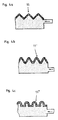
- FIGS. 4a to 4c 5 shows schematic cross sections through partial areas of further embodiments
- FIG. 5 schematically an oblique view of part of a within the scope of the invention usable tube absorber
- Fig. 7a to 7c and Fig. 8 schematically Various other configurations of tube absorbers, some with representation the basic arrangement.
- Fig. 1 shows a wheel 1 with a tire 2 in side view with one arranged above it Wheel arch 3.
- the main radiation directions of tire / road noise in the Latschlauf and in the Latschausmoor of the tire 2 are by bundles of arrows indicated.
- the wheel arch 3 is sound-absorbing Provide device 4 which the inner wall region of the wheel housing 3rd completely covers and is attached to the wheel arch 3 accordingly.
- the device 4 consists of a Rear wall 5, which is assigned to the wheel arch or abuts against it and fastened there is and an outer shell 6, wherein between the rear wall 5 and outer shell 6 Cavity remains.
- the outer shell 6 consists of a flexible, however material resistant to environmental influences and as impact-resistant as possible, for example made of rubber or a suitable plastic.
- the rear wall 5 can also made of such a material or a rigid material, for example consist of a plastic, which corresponds in shape to the wheel arch 3 is adjusted.
- the wheel arch 3 itself can form the rear wall.
- the outer shell is attached directly to the Radksten 3, this variant in all embodiments can be realized. With all Embodiments, it is also possible to the edge or side areas of the sound absorbing device with the rear wall and / or the outer shell to train or to provide separate side wall parts.
- the outer shell 6 is provided with a plurality of holes 8 so that the device acts as a hole absorber, the outer shell 6 itself has a thickness that in particular between 0.5 and 5 mm.
- the thickness will be according to the expected stress selected, the resonance frequency and the impedance of the Hole absorber can be influenced.
- the holes 8 are preferably one circular cross section and have different diameters. At In a version with a circular cross section, the diameter of the holes becomes 8 ⁇ 3 mm, in particular 0.1 to 1 mm, selected.
- Perforated area in the total area the outer shell 6 is between 5 and 80%, in particular 20 to 50%.
- the distribution the holes 8 can be done in a regular or irregular manner, whereby in this regard, care is taken to adapt to the expected sound field, especially with regard to the distribution or the range of the frequencies that occur, to achieve.
- Air supply line 7 can be pressurized with air pressure. This will be between the back wall 5 and the outer shell 6 set a distance of a few centimeters, depending on Interpretation is in particular 1 to 10 cm.
- the device 4 is therefore by the Activated overpressure as an absorbent element, the overpressure not using a pump shown is maintained.
- a variation in size allows the air pressure a further influence on the sound absorption properties of the Device 4.
- the overpressure has the beneficial effect that for one constant air flow is provided through the holes 8 to the outside, and thus on the one hand Clogging of the holes 8 due to dirt and on the other hand the ingress of water the inside of the device is prevented.
- the wheel arches the wheel also on the side partially cover, has an arrangement of the device 4 on the inner wall of the side covering part also has the advantage that cooling of the air flow Tire is achieved.
- a porous soundproofing can also be used Material 9, such as foam, glass wool, rock wool or the like to be ordered. This material can also be used as a soundproofing layer on the Rear wall 5 of the device 4 or directly on the wheel arch, if not a separate one Rear wall is intended to be attached.
- a support structure between the rear wall 5 and the outer shell 6, which, however, is not shown, can be provided to a certain extent from the outset To achieve formation of the device 4.
- the outer shell of the device with suitable geometric structures with a Height extension of a few centimeters, in particular from 1 to 10 cm, provided becomes.
- 4a, 4b and 4c show possible embodiments of such outer shells. Since these design variants otherwise show devices that the 2a corresponds to the following short description only referred to the separate design of the outer shells.
- Fig. 4a shows in cross section an embodiment in which the outer shell is designed in this way is that they are made of tetrahedral or pyramidal knobs 11th put together.
- 4b are conical Studs 11 'are provided, hemispherical studs 11' 'in the outer shell according to FIG. 4c.
- a system of tightly connected tubes acts as a tube absorber Tubes whose diameter is smaller than their length.
- Fig. 5 shows such a basic Structure.
- a tube absorber only causes a small change in impedance incident sound wave, there is also only a slight reflection. Sound absorbing mainly affects the friction of the sound pressure wave on the tube walls.
- a tube absorber can, as shown in FIG. 5, consist of a large number on its side walls connected single tubes exist.
- Fig. 6a shows one in the context of Present invention usable tube absorber 13, which as a solid plate with a plurality of closely spaced through holes 12 is executed.
- FIG 6b shows a plan view of a partial area of a tube absorber 13 ', which is shown in FIG grid-like plate is made and made of a system of rectangular Passage openings 12 'of various cross-sectional areas, at least in part common partitions 14 there.
- FIG. 6c A third embodiment variant of a tube absorber 13 ′′ is shown in FIG. 6c, where a honeycomb shape structured grid is present, which is thus made of regular cross-section Hexagonal structures 12 '' composed.
- 7a, 7b and 7c schematically show the arrangement of the tube absorber preferably at a distance of ⁇ 1 cm, in particular between 2 and 5 cm is in front of the sound absorbing device 4th
- 7a shows a variant in which the tube length and thus the thickness of the tube absorber 23 is kept constant.
- 7b shows the thickness of the tube absorber 23 'and thus the tube length over the extent of the tube absorber 23' be constantly changed, for example according to the roundness of the wheel arch.
- Fig. 7c shows an embodiment variant in which the tubes of the tube absorber 23 ′′ differ Have lengths, with an irregular distribution of the tubes chosen is.
- the actual lengths of the tubes are based on the existing installation space and the Desired absorption frequency or absorption power adjusted and can between 2 and 20 cm, preferably between 5 and 10 cm.
- the tube area percentage (Total sum of the tube cross sectional areas divided by the total front area of the Tube absorber) is expediently ⁇ 50%, in particular up to 95%.
- the tube cross-section can be varied over the tube length.
- the tube cross-section can be changed continuously, as shown, for example, with the tube absorber 33 in FIG. 8.
- the tubes can also act as ⁇ / 4 resonators for different frequencies.
- the angle ⁇ (FIG. 8) determining the change in cross section is ⁇ 5 ° is.
- Tube absorbers have high rigidity and strength and therefore offer good protection the device according to the invention against stone chips, pollution, snow or Water splash.
- the tubes of the tube absorbers also work when the road is wet Spray formation counter.
- Arrangement of a tube absorber also has a positive effect on ventilation and air cooling of the brakes and tires.
Abstract
Description
Die vorliegende Erfindung betrifft eine am Radkasten eines Kraftfahrzeuges anzubringende, als passiver Schallabsorber wirkende Vorrichtung zur Reduktion des über die Luft übertragenen Anteiles des vom Kraftfahrzeug emittierten Reifen/Fahrbahngeräusches, wobei die Vorrichtung den Radkasten zumindest zum Teil überdeckt und eine zum Radkasten zu einem Innenraum umschließende Außenhülle sowie gegebenenfalls eine dem Radkasten zugeordnete Rückwand aufweist.The present invention relates to a to be attached to the wheel arch of a motor vehicle, as a passive sound absorber device for reducing airborne emissions transmitted part of the tire / road noise emitted by the motor vehicle, wherein the device at least partially covers the wheel arch and one for Wheel arch to an inner shell enclosing an interior and, if necessary, a Has wheel arch associated rear wall.
In den letzten Jahren wurde seitens der Kraftfahrzeughersteller schalldämmenden Maßnahmen, die vor allem die Motorgeräusche im Außengeräusch und deren Übertragung ins Fahrzeuginnere vermindern, verstärkt Aufmerksamkeit geschenkt. Zu diesen Maßnahmen zählt beispielsweise die Anbringung von schalldämmenden Motorkapselungen, was jedoch zur Folge hat, daß das Reifen/Fahrbahngeräusch mehr und mehr zur dominierenden Lärmquelle wird. Dabei entwickeln LKW-Reifen aus konstruktionsbedingten Gründen ein als störender empfundenes Rollgeräusch als PKW-Reifen. Die hauptsächliche Abstrahlung von Schalleistung erfolgt bei PKW-Reifen in einem Frequenzbereich von ca. 500 bis 2.000 Hz, bei LKW-Reifen in einem Frequenzbereich von ca. 400 bis 1.200 Hz.In recent years, vehicle manufacturers have been sound-absorbing Measures, especially the engine noise in outside noise and its transmission Reduce inside the vehicle, pay more attention. To this Measures include, for example, the installation of soundproof engine enclosures, however, which has the consequence that the tire / road noise more and more dominant source of noise. Here, truck tires develop from design-related Found a disturbing rolling noise than car tires. The main one Radiation power is emitted from car tires in a frequency range of approx. 500 to 2,000 Hz, for truck tires in a frequency range of approx. 400 to 1,200 Hz.
Auch seitens der Reifenhersteller werden seit vielen Jahren Maßnahmen getroffen und ständig weiterentwickelt, die insbesondere darauf abzielen, das Reifen/Fahrbahngeräusch derart zu beeinflussen, daß eine Verteilung der auftretenden Frequenzen auf ein breiteres Frequenzband erfolgt, was subjektiv als angenehmer empfunden wird, als eine Schallabstrahlung mit vorherrschenden Frequenzen. Der Großteil der gesetzten Maßnahmen erfolgt am Laufstreifenprofil der Reifen selbst, indem grundsätzlich das Verfahren der Pitchlängenvariation, welches in Einzelaspekten immer wieder verbessert wird, angewandt wird.Measures have also been taken by tire manufacturers for many years constantly evolving, specifically aimed at the tire / road noise to influence such that a distribution of the frequencies occurring on a wider Frequency band occurs, which is subjectively perceived as more pleasant than one Sound radiation with prevailing frequencies. The majority of the seeded Measures are taken on the tread pattern of the tires themselves, by basically doing that Process of pitch length variation, which improves again and again in individual aspects is applied.
Aus der DE 42 41 518 C1 ist eine am Rad eines Kraftfahrzeuges zu befestigende Umkleidung bekannt, die als ein doppelwandiges und formstabiles Flächengebilde ausgestaltet ist und ein System von Helmholtz-Resonatoren aufweist. Diese Vorrichtung wirkt als passiver Schallabsorber und umfaßt somit eine Außenhülle, die dem Rad zugewandt ist, und eine dem Radkasten zugewandte Rückwand. Dem Rad ist eine formstabile und somit starre Folie zugewandt, die der Gefahr der Verschmutzung bzw. der Anlagerung von Schmutz, einfrierendem Wasser und auch Schnee ausgesetzt ist. Dadurch kann die gesamte Vorrichtung ihre Wirksamkeit als Schallabsorber verlieren.From DE 42 41 518 C1 is to be attached to the wheel of a motor vehicle Cladding known as a double-walled and dimensionally stable fabric is designed and has a system of Helmholtz resonators. This device acts as a passive sound absorber and thus includes an outer shell that the wheel is facing, and a rear wall facing the wheel arch. The bike is one dimensionally stable and thus rigid film facing the risk of contamination or Accumulation of dirt, freezing water and also snow is exposed. Thereby the entire device can lose its effectiveness as a sound absorber.
Der Erfindung liegt die Aufgabe zugrunde, eine als passiver Schallabsorber wirkende Vorrichtung gemäß der eingangs beschriebenen Art derart auszugestalten, daß die Gefahr des Verlustes der Wirksamkeit als Schallabsorber aufgrund von Verschmutzungen, einfrierendem Wasser und auch Schnee wesentlich verringert ist.The invention has for its object to act as a passive sound absorber To design the device according to the type described above such that the danger loss of effectiveness as a sound absorber due to contamination, freezing water and snow is significantly reduced.
Die Aufgabe wird erfindungsgemäß dadurch gelöst, daß die Außenhülle als Lochabsorber ausgeführt ist und aus einem biegeweichen Material, beispielsweise aus Gummi oder einem Kunststoff, besteht.The object is achieved in that the outer shell as a hole absorber is executed and made of a flexible material, such as rubber or a Plastic.
Nach der Erfindung wird in unmittelbarer Nähe und in den Schallabstrahlungsrichtungen des abrollenden Reifens eine wirkungsvolle Maßnahme zur Schallabsorption getroffen, die auf die gewünschte Schallabsorption bezüglich der Frequenzbereiche und/oder der räumlichen Ausprägung der Schalleistung entsprechend abgestimmt werden kann. Die erfindungsgemäße Ausführung als Lochabsorber hat einerseits den Vorteil, daß die Löcher gegenüber einer Ausführung mit Helmholtz-Resonatoren vergleichsweise klein ausgeführt werden, so daß die Gefahr des Einbringens von Wasser oder Schmutz in den Innenraum der Vorrichtung wesentlich verringert ist. Dadurch, daß die Außenhülle aus einem biegeweichen Material besteht, ist sichergestellt, daß angelagerter Schmutz leicht abfallen kann und die Wirksamkeit der Vorrichtung als Schallabsorber erhalten bleibt.According to the invention is in the immediate vicinity and in the sound radiation directions of the rolling tire, an effective measure of sound absorption is taken the desired sound absorption with regard to the frequency ranges and / or the spatial Characteristics of the sound power can be adjusted accordingly. The Design according to the invention as a hole absorber has the advantage that the holes Compared to a version with Helmholtz resonators, it is comparatively small be so that the risk of introducing water or dirt into the interior the device is significantly reduced. The fact that the outer shell made of a flexible material exists, it is ensured that accumulated dirt can easily fall off and Effectiveness of the device as a sound absorber is retained.
In vorteilhafter Ausgestaltung der Erfindung ist der Innenraum zwischen Außenhülle und der Rückwand bzw. dem Radkasten mit Druckluft beaufschlagbar. Durch die Beaufschlagung mit Luftdruck wird die Einrichtung in ihrer Funktion als schallabsorbierendes Element aktiviert. Dabei kann durch die Größe des Überdruckes die Geometrie der Anordnung und damit das Absorptionsverhalten entsprechend beeinflußt werden. Durch den Überdruck im Inneren wird ferner für einen ständigen Luftstrom nach außen gesorgt, so daß ein Zusetzen der Löcher durch Schmutz oder durch das Eindringen von Wasser wirkungsvoll verhindert wird. Bei dieser Ausführungsform ist es dabei günstig, wenn im Innenraum der Vorrichtung eine Stützkonstruktion vorgesehen wird, um von vornherein eine gewisse Formung der Vorrichtung zu erzielen. In an advantageous embodiment of the invention, the interior between the outer shell and the Compressed air can be applied to the rear wall or the wheel arch. By the application with air pressure, the device functions as a sound absorbing element activated. The geometry of the arrangement and so that the absorption behavior can be influenced accordingly. Due to the overpressure in the Inside is also provided for a constant airflow to the outside, so that clogging which effectively prevents holes from dirt or water ingress becomes. In this embodiment, it is advantageous if in the interior of the device a support structure is provided in order to have a certain shape from the outset To achieve device.
Um eine Schallabsorption in einem möglichst breitbandigen Frequenzbereich zu erreichen, ist es günstig, wenn die Löcher in der Außenhülle unterschiedliche Lochflächengrößen aufweisen und/oder unregelmäßig verteilt sind, wobei die Löcher bevorzugt mit einem kreisförmigen Querschnitt versehen werden.In order to achieve sound absorption in the widest possible frequency range, it is advantageous if the holes in the outer shell have different hole surface sizes have and / or are distributed irregularly, the holes preferably with a circular cross section.
Ist die Vorrichtung mit einer biegeweichen Außenhülle versehen, bei der eine Innenbeaufschlagung mit Druckluft vorgesehen ist, so ist es günstig, wenn der Durchmesser der Löcher kleiner gewählt wird als bei einer Vorrichtung, die mit einer starren Außenhülle versehen ist. Bei einer Vorrichtung mit biegeweicher Außenhülle beträgt dabei der Durchmesser der Löcher ≤ 3 mm, insbesondere zwischen 0,1 und 1 mm.If the device is provided with a flexible outer shell, in which one Internal pressurization is provided, so it is beneficial if the diameter of the holes is chosen to be smaller than that of a device with a rigid outer shell is provided. In the case of a device with a flexible outer casing, the Diameter of the holes ≤ 3 mm, in particular between 0.1 and 1 mm.
Die Schallabsorptionseigenschaften lassen sich ferner dadurch günstig beeinflussen, daß im Inneren der Vorrichtung insbesondere poröses schalldämmendes Material, beispielsweise Schaumstoff, Glaswolle, Steinwolle oder dergleichen, eingebracht ist. Dabei kann das schalldämmende Material als Schicht eingebracht sein oder auch das Innere der Vorrichtung komplett ausfüllen. Bei einer weiteren vorteilhaften Weiterentwicklung der Erfindung ist vorgesehen, daß die Außenhülle geometrisch strukturiert ist, insbesondere mit Noppen versehen ist, die vorzugsweise kegel-, pyramiden-, tetraeder-oder halbkugelförmig gestaltet sind. Auch diese Maßnahme macht eine weitere Abstimmung bzw. Beeinflussung der Schallabsorptionseigenschaften möglich.The sound absorption properties can also be influenced favorably by that in particular porous sound-absorbing material inside the device, for example foam, glass wool, rock wool or the like is introduced. Here can the sound-absorbing material be introduced as a layer or the inside of the Fill out the device completely. In a further advantageous further development of the The invention provides that the outer shell is structured geometrically, in particular is provided with knobs, which are preferably conical, pyramidal, tetrahedral or are designed hemispherical. This measure also makes a further vote or influencing the sound absorption properties possible.
Eine weitere günstige Beeinflussung der Schallabsorptionseigenschaften ist dadurch möglich, daß der Vorrichtung eine als Röhrenabsorber wirkende Einrichtung vorgeordnet ist. Dabei hat diese Maßnahme noch ferner den Vorteil, daß sie einen sehr guten Schutz vor Steinschlag, Schmutz und Spritzwasser darstellt.This has a further favorable influence on the sound absorption properties possible that the device is preceded by a device acting as a tube absorber is. This measure has the further advantage that it offers very good protection against stone chips, dirt and splash water.
Eine besonders einfache Ausgestaltung des Röhrenabsorbers besteht darin, daß sich dieser aus einer Vielzahl von dicht nebeneinander angeordneten Einzelröhren zusmmensetzt.A particularly simple embodiment of the tube absorber is that this consists of a large number of individual tubes arranged close to each other put together.
Bei einer weiteren Ausführungsform ist der Röhrenabsorber als massive Platte mit einer Vielzahl von eng beabstandeten Durchgangsbohrungen ausgeführt.In a further embodiment, the tube absorber is in the form of a solid plate with a Variety of closely spaced through holes.
Eine weitere einfache Variante der Ausführung eines Röhrenabsorbers besteht darin, daß der Röhrenabsorber als Gitter ausgeführt ist, dessen Durchtrittsöffnungen insbesondere unterschiedlich groß sind.Another simple variant of the design of a tube absorber is that the tube absorber is designed as a grid, the passage openings in particular are different sizes.
Bei einer weiteren bevorzugten Ausführungsvariante ist der Röhrenabsorber als ein eine wabenförmige Struktur aufweisendes Gitter gestaltet. Die Anordnung des Röhrenabsorbers vor der Vorrichtung erfolgt bevorzugt in einem gewissen Abstand, der ≥ 1 cm, insbesondere zwischen 2 und 5 cm, beträgt.In a further preferred embodiment variant, the tube absorber is as one designed with honeycomb structure. The arrangement of the tube absorber in front of the device is preferably at a certain distance that is ≥ 1 cm, in particular between 2 and 5 cm.
Von Vorteil kann auch sein, wenn der Röhrenabsorber derart gestaltet wird, daß sich seine Dicke zumindest über einen Bereich seiner Erstreckung insbesondere stetig ändertIt can also be advantageous if the tube absorber is designed in such a way that its thickness changes continuously, at least over a region of its extent
Der Röhrenabsorber kann sich ferner aus Röhren unterschiedlicher Länge zusammensetzen. Zusätzlich kann auch noch der Röhrenquerschnitt über die Röhrenlänge variiert werden, wobei eine stetige Änderung des Röhrenquerschnittes bevorzugt ist. Die Röhren können so zusätzlich als λ/4-Resonatoren für bestimmte Frequenzen wirken. The tube absorber can also be composed of tubes of different lengths. In addition, the tube cross-section can also vary over the tube length be, with a constant change in the tube cross section is preferred. The tubes can also act as λ / 4 resonators for certain frequencies.
Weitere Merkmale, Vorteile und Einzelheiten der Erfindung werden nun anhand der Zeichnung, die einige Ausführungsbeispiele darstellt, näher beschrieben. Dabei zeigt Fig. 1 ein Rad mit darüber angeordnetem Radkasten in Seitensansicht in schematischer Darstellung, Fig. 2a, zeigt schematisch einen Querschnitt durch jeweils einen Teilbereich einer Ausführungsform der Erfindung, Fig. 3a eine Draufsicht auf einen Teilbereich der in Fig. 2a dargestellten Variante, Fig. 4a bis 4c schematische Querschnitte durch Teilbereiche weiterer Ausführungsformen, Fig. 5 schematisch eine Schrägansicht eines Teiles eines im Rahmen der Erfindung einsetzbaren Röhrenabsorbers, Fig. 6a bis 6c Draufsichten auf Teile weiterer Ausführungsformen eines Röhrenabsorbers, Fig. 7a bis 7c und Fig. 8 schematisch verschiedene weitere Ausgestaltungen von Röhrenabsorbern zum Teil unter Darstellung der grundsätzlichen Anordnung.Further features, advantages and details of the invention are now based on the Drawing, which illustrates some embodiments, described in more detail. Fig. 1 shows a wheel with a wheel arch arranged above it in a side view in schematic Representation, Fig. 2a, shows schematically a cross section through one Part of an embodiment of the invention, Fig. 3a is a plan view to a partial area of the variant shown in FIG. 2a, FIGS. 4a to 4c 5 shows schematic cross sections through partial areas of further embodiments, FIG. 5 schematically an oblique view of part of a within the scope of the invention usable tube absorber, Fig. 6a to 6c top views of parts of other Embodiments of a tube absorber, Fig. 7a to 7c and Fig. 8 schematically Various other configurations of tube absorbers, some with representation the basic arrangement.
Fig. 1 zeigt ein Rad 1 mit einem Reifen 2 in Seitenansicht mit einem darüber angeordneten
Radkasten 3. Die hauptsächlichen Abstrahlrichtungen des Reifen/Fahrbahngeräusches
im Latscheinlauf und im Latschauslauf des Reifens 2 sind durch Pfeilbündel
angedeutet. Gemäß der vorliegenden Erfindung ist der Radkasten 3 mit einer schallabsorbierenden
Vorrichtung 4 versehen, die den Innenwandbereich des Radkastens 3
komplett abdeckt und am Radkasten 3 entsprechend befestigt ist.Fig. 1 shows a
Beim Ausführungsbeispiel gemäß Fig. 2a und Fig. 3a besteht die Vorrichtung 4 aus einer
Rückwand 5, die dem Radkasten zugeordnet ist bzw. an diesem anliegt und dort befestigt
wird und einer Außenhülle 6, wobei zwischen Rückwand 5 und Außenhülle 6 ein
Hohlraum verbleibt. Die Außenhülle 6 besteht aus einem biegeweichen, jedoch
gegenüber Umwelteinflüssen resistenten und möglichstschlagzähem Material,
beispielsweise aus Gummi oder aus einem geeigneten Kunststoff. Die Rückwand 5 kann
ebenfalls aus einem solchen Material oder auch einem starren Material, beispielsweise
aus einem Kunststoff bestehen, welches in seiner Form dem Radkasten 3 entsprechend
angepaßt ist. Alternativ dazu kann der Radkasten 3 selbst die Rückwand bilden. In
diesem Fall wird die Außenhülle direkt am Radksten 3 befestigt, wobei diese Variante bei
sämtlichen Ausführungsbeispielen realisiert werden kann. Bei sämtlichen
Ausführungsbeispielen ist es ferner möglich, die Rand- bzw. Seitenbereiche der
schallabsorbierenden Vorrichtung mit der Rückwand und/oder der Außenhülle
mitzubilden oder gesonderte Seitenwandteile vorzusehen. In the exemplary embodiment according to FIGS. 2a and 3a, the
Die Außenhülle 6 ist mit einer Vielzahl von Löchern 8 versehen, so daß die Vorrichtung
als Lochabsorber wirkt, die Außenhülle 6 selbst weist eine Dicke, die insbesondere zwischen
0,5 und 5 mm beträgt, auf. Die Dicke wird entsprechend der erwarteten Beanspruchung
gewählt, wobei ferner über die Dicke die Resonanzfrequenz und die Impedanz des
Lochabsorbers beeinflußbar ist. Wie Fig. 3a zeigt sind die Löcher 8 bevorzugt mit einem
kreisförmigen Querschnitt versehen und weisen verschiedene Durchmesser auf. Bei
einer Ausführung mit kreisförmigem Querschnitt wird der Durchmesser der Löcher 8 ≤ 3
mm, insbesondere 0,1 bis 1 mm, gewählt. Der Lochflächenanteil an der Gesamtfläche
der Außenhülle 6 beträgt zwischen 5 und 80 %, insbesondere 20 bis 50 %. Die Verteilung
der Löcher 8 kann auf regelmäßige oder unregelmäßige Art und Weise erfolgen, wobei
diesbezüglich darauf geachtet wird, eine Anpassung an das zu erwartende Schallfeld,
insbesondere was die Verteilung bzw. den Bereich der auftretenden Frequenzen betrifft,
zu erzielen.The
Der zwischen der Rückwand 5 und der Außenhülle 6 verbleibende Raum ist über eine
Luftzufuhrleitung 7 mit Luftdruck beaufschlagbar. Dadurch wird zwischen der Rückwand
5 und der Außenhülle 6 ein Abstand von einigen Zentimetern eingestellt, der je nach
Auslegung insbesondere 1 bis 10 cm beträgt. Die Vorrichtung 4 wird daher durch den
Überdruck als absorbierendes Element aktiviert, wobei der Überdruck mittels einer nicht
dargestellten Pumpe aufrecht erhalten wird. Zusätzlich erlaubt eine Variation der Größe
des Luftdruckes eine weitere Beeinflussung der Schallabsorptionseigenschaften der
Vorrichtung 4. Dabei hat der Überdruck günstigerweise noch die Wirkung, daß für einen
ständigen Luftstrom über die Löcher 8 nach außen gesorgt wird, und somit einerseits ein
Zusetzen der Löcher 8 durch Schmutz und andererseits das Eindringen von Wasser in
das Vorrichtungsinnere verhindert wird. Bei Radkästen, die das Rad auch seitlich
teilweise abdecken, hat eine Anordnung der Vorrichtung 4 an der Innenwand des seitlich
abdeckenden Teiles ferner den Vorteil, daß durch den Luftstrom eine Kühlung des
Reifens erzielt wird.The space remaining between the
Im Innenraum der Vorrichtung 4 kann ferner zusätzlich ein poröses schalldämmendes
Material 9, wie beispielsweise Schaumstoff, Glaswolle, Steinwolle oder dergleichen
angeordnet werden. Dieses Material kann auch als schalldämmende Schicht auf der
Rückwand 5 der Vorrichtung 4 oder direkt am Radkasten, falls keine gesonderte
Rückwand vorgesehen ist, angebracht werden. In the interior of the
Zusätzlich kann zwischen der Rückwand 5 und der Außenhülle 6 eine Stützkonstruktion,
die jedoch nicht dargestellt ist, vorgesehen werden, um von vornherein eine gewisse
Formung der Vorrichtung 4 zu erzielen. In addition, a support structure, between the
Zur weiteren Verbesserung der Schallabsorptionseigenschaften ist es weiters günstig, wenn die Außenhülle der Vorrichtung mit geeigneten geometrischen Strukturen mit einer Höhenerstreckung von einigen Zentimetern, insbesondere von 1 bis 10 cm, versehen wird. Die Fig. 4a, 4b und 4c zeigen mögliche Ausführungsformen derart gestalteter Außenhüllen. Da diese Ausführungsvarianten ansonsten Vorrichtungen zeigen, die jener gemäß Fig. 2a entspricht, wird in der nachfolgenden kurzen Beschreibung lediglich auf die gesonderte Ausgestaltung der Außenhüllen Bezug genommen. Fig. 4a zeigt dabei im Querschnitt eine Ausführungsform, bei der die Außenhülle derart ausgeführt ist, daß sie sich aus tetraeder- oder pyramidenförmigen Noppen 11 zusammensetzt. Bei der Ausführungsform nach Fig. 4b sind kegelförmig gestaltete Noppen 11' vorgesehen, in der Außenhülle gemäß Fig. 4c halbkugelförmige Noppen 11''.To further improve the sound absorption properties, it is also favorable if the outer shell of the device with suitable geometric structures with a Height extension of a few centimeters, in particular from 1 to 10 cm, provided becomes. 4a, 4b and 4c show possible embodiments of such outer shells. Since these design variants otherwise show devices that the 2a corresponds to the following short description only referred to the separate design of the outer shells. Fig. 4a shows in cross section an embodiment in which the outer shell is designed in this way is that they are made of tetrahedral or pyramidal knobs 11th put together. 4b are conical Studs 11 'are provided, hemispherical studs 11' 'in the outer shell according to FIG. 4c.
Eine weitere Verbesserung der Schallabsorptionseigenschaften einer gemäß der vorliegenden Erfindung ausgeführten Vorrichtung läßt sich dadurch erzielen, daß vor der Vorrichtung, wie nun im folgenden und anhand der Zeichnungsfiguren 5 bis 7 beschrieben wird, eine als Röhrenabsorber wirkende Einrichtung angeordnet wird.Another improvement in sound absorption properties according to the present Device implemented according to the invention can be achieved in that in front of the device, as now described below and with reference to the drawing figures 5 to 7 a device acting as a tube absorber is arranged.
Grundsätzlich wirkt als Röhrenabsorber ein System von fest miteinander verbundenen Röhren, deren Durchmesser kleiner ist als ihre Länge. Fig. 5 zeigt eine solche grundsätzliche Struktur. Ein Röhrenabsorber bewirkt nur eine kleine Impedanzänderung der einfallenden Schallwelle, es tritt auch nur eine geringe Reflexion auf. Schallabsorbierend wirkt vor allem die Reibung der Schalldruckwelle an den Röhrenwänden.Basically, a system of tightly connected tubes acts as a tube absorber Tubes whose diameter is smaller than their length. Fig. 5 shows such a basic Structure. A tube absorber only causes a small change in impedance incident sound wave, there is also only a slight reflection. Sound absorbing mainly affects the friction of the sound pressure wave on the tube walls.
Ein Röhrenabsorber kann nun, wie Fig. 5 zeigt, aus einer Vielzahl durch an ihren Seitenwänden
verbundenen Einzelröhren bestehen. Fig. 6a zeigt einen im Rahmen der
vorliegenden Erfindung einsetzbarer Röhrenabsorber 13, welcher als massive Platte mit
einer Vielzahl von eng beabstandeten Durchgangsbohrungen 12 ausgeführt ist.A tube absorber can, as shown in FIG. 5, consist of a large number on its side walls
connected single tubes exist. Fig. 6a shows one in the context of
Present invention
Fig. 6b zeigt eine Draufsicht auf einen Teilbereich eines Röhrenabsorbers 13', der als
gitterartige Platte ausgeführt ist und aus einem System von rechteckförmigen
Durchtrittsöffnungen 12' verschiedenster Querschnittsfläche mit zumindest zum Teil
gemeinsamen Trennwänden 14 besteht.6b shows a plan view of a partial area of a tube absorber 13 ', which is shown in FIG
grid-like plate is made and made of a system of rectangular
Passage openings 12 'of various cross-sectional areas, at least in part
Eine dritte Ausführungsvariante eines Röhrenabsorbers 13'' zeigt Fig. 6c, wo ein wabenförmig
strukturiertes Gitter vorliegt, das sich somit aus im Querschnitt regelmäßige
Sechsecke bildenden Strukturen 12'' zusammensetzt.A third embodiment variant of a
Hinsichtlich der Ausgestaltung des Röhrenabsorbers stehen dem Fachmann eine Vielzahl von Möglichkeiten offen, wobei in Fig. 6a, 6b und 6c lediglich und beispielhaft drei Ausführungsformen dargestellt sind.With regard to the design of the tube absorber, a large number are available to the person skilled in the art of possibilities open, with only three examples in FIGS. 6a, 6b and 6c Embodiments are shown.
Wie Fig. 7a, 7b und 7c schematisch zeigen erfolgt die Anordnung des Röhrenabsorbers bevorzugt in einem Abstand, der ≥ 1 cm, insbesondere zwischen 2 und 5 cm, gewählt wird vor der schallabsorbierenden Vorrichtung 4.7a, 7b and 7c schematically show the arrangement of the tube absorber preferably at a distance of ≥ 1 cm, in particular between 2 and 5 cm is in front of the sound absorbing device 4th
Fig. 7a zeigt dabei eine Variante, bei der die Röhrenlänge und somit die Dicke des Röhrenabsorbers
23 konstant gehalten ist. Wie Fig. 7b zeigt kann die Dicke des Röhrenabsorbers
23' und somit die Röhrenlänge über die Erstreckung des Röhrenabsorbers 23'
stetig geändert werden, beispielsweise entsprechend der Rundung des Radkastens. Fig.
7c zeigt eine Ausführungsvariante, bei der die Röhren des Röhrenabsorbers 23'' unterschiedliche
Längen aufweisen, wobei eine unregelmäßige Verteilung der Röhren gewählt
ist.7a shows a variant in which the tube length and thus the thickness of the
Die tatsächlichen Längen der Röhren werden an den vorhandenen Einbauraum und die gewünschte Absorptionsfrequenz bzw. Absorptionsleistung angepaßt und kann zwischen 2 und 20 cm, bevorzugt zwischen 5 und 10 cm, betragen. Der Röhrenflächenanteil (Gesamtsumme der Röhrenquerschnittsflächen geteilt durch die Gesamtfrontfläche des Röhrenabsorbers) beträgt zweckmäßigerweise ≥ 50 %, insbesondere bis zu 95 %.The actual lengths of the tubes are based on the existing installation space and the Desired absorption frequency or absorption power adjusted and can between 2 and 20 cm, preferably between 5 and 10 cm. The tube area percentage (Total sum of the tube cross sectional areas divided by the total front area of the Tube absorber) is expediently ≥ 50%, in particular up to 95%.
Zusätzlich kann auch der Röhrenquerschnitt über die Röhrenlänge variiert werden. Vorteilhafterweise
kann eine stetige Änderung des Röhrenquerschnittes vorgenommen werden,
wie es beispielsweise beim Röhrenabsorber 33 in Fig. 8 gezeigt ist. Die Röhren
können so zusätzlich als λ/4-Resonatoren für verschiedene Frequenzen wirken. Dabei
ist es günstig, wenn der die Querschnittsänderung bestimmende Winkel α (Fig. 8) ≤ 5°
beträgt.In addition, the tube cross-section can be varied over the tube length. Advantageously
the tube cross-section can be changed continuously,
as shown, for example, with the
Neben den akustischen Vorteilen hat die Kombination der erfindungsgemäßen Vorrichtung mit Röhrenabsorbern noch weitere Vorteile. Bedingt durch ihre Konstruktion haben Röhrenabsorber eine hohe Steifigkeit und Festigkeit und bieten daher einen guten Schutz der erfindungsgemäßen Vorrichtung vor Steinschlag, Verschmutzung, Schnee oder Spritzwasser. Die Röhren der Röhrenabsorber wirken ferner bei nasser Fahrbahn der Sprühnebelbildung entgegen.In addition to the acoustic advantages, the combination of the device according to the invention has with tube absorbers there are even more advantages. Due to their construction Tube absorbers have high rigidity and strength and therefore offer good protection the device according to the invention against stone chips, pollution, snow or Water splash. The tubes of the tube absorbers also work when the road is wet Spray formation counter.
In Kombination mit einer erfindungsgemäßen Vorrichtung, wie sie in Fig. 2a dargestellt ist, also bei einem Lochabsorber, wo ein freier Luftdurchtritt gegeben ist, wirkt sich die Anordnung eines Röhrenabsorbers auch noch positiv auf die Belüftung und Luftkühlung der Bremsen und Reifen aus.In combination with a device according to the invention, as shown in Fig. 2a is, so with a hole absorber, where there is free air passage, the Arrangement of a tube absorber also has a positive effect on ventilation and air cooling of the brakes and tires.
Schließlich wird noch darauf verwiesen, daß die beschriebenen und dargestellten Ausführungsvarianten
auf unterschiedliche Art und Weise kombiniert werden können. Erwähnt
wird ferner, daß nicht der gesamte Radkasten 3 mit einer Vorrichtung gemäß der
vorliegenden Erfindung versehen werden muß. Die Vorrichtung kann lediglich dort vorgesehen
werden, wo das Schallfeld am größten ist. Dabei ist es auch möglich, die Vorrichtung
aus Einzelteilen zusammenzusetzen, die jeweils erfindungsgemäß ausgeführt sind.Finally, reference is made to the fact that the embodiment variants described and illustrated
can be combined in different ways. Mentioned
is further that not the
Claims (17)
- Apparatus, which is to be mounted on the wheel housing of an automotive vehicle and acts as a passive sound absorber, for reducing the proportion, which is transmitted via the air, of the tyre/roadway noise emitted by the automotive vehicle, the apparatus covering the wheel housing at least partially and having an external sleeve, which surrounds an internal space extending to the wheel housing, and possibly a rear wall associated with the wheel housing (3), characterised in that the external sleeve (6) is configured as a perforated absorber and is formed from a flexible material, for example rubber or a plastics material.
- Apparatus according to claim 1, characterised in that compressed air can act upon the internal space between the external sleeve (6) and the rear wall (5), or respectively the wheel housing (3).
- Apparatus according to claim 1 or 2, characterised in that a support structure is provided in the internal space.
- Apparatus according to one of claims 1 to 3, characterised in that the perforations (8) in the external sleeve (6), which is configured as a perforated absorber, have perforation areas of different sizes and/or are irregularly distributed, the perforations (8) being preferably provided with a circular cross-section.
- Apparatus according to claim 4, characterised in that the diameter of the perforations (8) in the external sleeve (6) is ≤ 3 mm, more especially between 0.1 and 1 mm.
- Apparatus according to one of claims 1 to 5, characterised in that more especially porous, sound-reducing material (9), for example expanded plastic foam, glass wool, rock wool or the like, is introduced in its internal space.
- Apparatus according to claim 6, characterised in that the sound-reducing material is introduced as a layer or even completely fills the internal space.
- Apparatus according to one of claims 1 to 7, characterised in that the external sleeve (6) has a geometrical structure and is more especially provided with knubs (11, 11', 11''), which preferably have conical, tetrahedral, pyramid-shaped or hemispherical configurations.
- Apparatus according to one of claims 1 to 8, characterised in that an arrangement, which acts as a tube-type absorber (13, 13', 13'', 23, 23', 23'', 33), is disposed in front of said apparatus.
- Apparatus according to claim 9, characterised in that the tube-type absorber (23) comprises a plurality of interconnected individual tubes.
- Apparatus according to claim 9, characterised in that the tube-type absorber (13) is configured as a solid plate having a plurality of closely spaced through-bores (12).
- Apparatus according to claim 9, characterised in that the tube-type absorber (13') is configured as a lattice having through-apertures (12') of different sizes.
- Apparatus according to claim 9, characterised in that the tube-type absorber (13'') is configured as a lattice having a honeycomb structure.
- Apparatus according to one of claims 9 to 13, characterised in that the tube-type absorber (13, 13', 13'', 23, 23', 23'', 33) is disposed at a spacing in front of the apparatus (4), which spacing is ≥ 1 cm, more especially between 2 and 5 cm.
- Apparatus according to one of claims 9 to 14, characterised in that the thickness of the tube-type absorber (23') changes more especially constantly at least over a region of its extension.
- Apparatus according to one of claims 9 to 15, characterised in that the tube-type absorber (23'') comprises tubes of different lengths.
- Apparatus according to one of claims 9 to 16, characterised in that the tubular cross-section is varied over the tube length, the change in cross-section being more especially constant.
Applications Claiming Priority (2)
| Application Number | Priority Date | Filing Date | Title |
|---|---|---|---|
| DE4415983A DE4415983C2 (en) | 1994-05-06 | 1994-05-06 | Device to be attached to the wheel arch of a motor vehicle and acting as a passive sound absorber |
| DE4415983 | 1994-05-06 |
Publications (3)
| Publication Number | Publication Date |
|---|---|
| EP0680866A1 EP0680866A1 (en) | 1995-11-08 |
| EP0680866B1 EP0680866B1 (en) | 1997-07-16 |
| EP0680866B2 true EP0680866B2 (en) | 2000-09-20 |
Family
ID=6517440
Family Applications (1)
| Application Number | Title | Priority Date | Filing Date |
|---|---|---|---|
| EP95106121A Expired - Lifetime EP0680866B2 (en) | 1994-05-06 | 1995-04-24 | Assembly for reducing tyre/road surface noise |
Country Status (3)
| Country | Link |
|---|---|
| EP (1) | EP0680866B2 (en) |
| AT (1) | ATE155413T1 (en) |
| DE (2) | DE4415983C2 (en) |
Families Citing this family (10)
| Publication number | Priority date | Publication date | Assignee | Title |
|---|---|---|---|---|
| DE19548728C1 (en) | 1995-12-23 | 1997-01-16 | Continental Ag | Vehicle with tires and with at least one sound absorbing device |
| FR2764859B1 (en) * | 1997-06-23 | 1999-07-30 | Renault | DEVICE FOR PROTECTING A STEERING WHEEL OF A MOTOR VEHICLE |
| DE19817567C2 (en) * | 1998-04-20 | 2000-08-10 | Stankiewicz Gmbh | Wheel arch part for vehicles |
| BR9909585A (en) * | 1998-05-12 | 2001-01-30 | Rieter Automotive Int Ag | Acoustic insulation component for vehicles |
| DE10133425A1 (en) | 2001-07-10 | 2003-01-30 | Hp Chem Pelzer Res & Dev Ltd | Vehicle wheel house |
| EP1655178A1 (en) | 2004-11-05 | 2006-05-10 | Peugeot Citroen Automobiles SA | Vehicle equipment part having acoustic absorption characteristics, method of manufacturing the same and use in a mudguard |
| US7748184B1 (en) | 2005-02-09 | 2010-07-06 | Intellectual Property Holdings, Llc | Body panel having improved stiffness and method of making |
| CN102152814A (en) * | 2011-03-05 | 2011-08-17 | 冯政 | Air sac type mud guard |
| DE102016114314A1 (en) * | 2016-08-03 | 2018-02-08 | Sennheiser Electronic Gmbh & Co. Kg | Method for producing an acoustic resistance and acoustic resistance |
| WO2020082098A1 (en) * | 2018-10-24 | 2020-04-30 | Wyremba Christian | Device for reducing tyre noise |
Citations (5)
| Publication number | Priority date | Publication date | Assignee | Title |
|---|---|---|---|---|
| DE2515127A1 (en) † | 1974-04-08 | 1975-10-16 | Lockheed Aircraft Corp | SOUND-ABSORBING CELL CONSTRUCTION |
| DE3409404A1 (en) † | 1983-11-30 | 1985-09-26 | Dr. Alois Stankiewicz GmbH, 3101 Adelheidsdorf | CYCLING PART |
| DE3913347A1 (en) † | 1989-04-22 | 1990-10-25 | Stocksmeier Uwe | Sound-insulating layer for flat surface - comprises regular hollow spaces enclosed by paper-strip walls |
| DE4011705A1 (en) † | 1990-04-11 | 1991-10-17 | Freudenberg Carl Fa | AIR SOUND ABSORBING MOLDED PART |
| EP0509166A1 (en) † | 1989-10-26 | 1992-10-21 | Rohr Industries, Inc. | Honeycomb noise attenuation structure |
Family Cites Families (6)
| Publication number | Priority date | Publication date | Assignee | Title |
|---|---|---|---|---|
| DE1008596B (en) * | 1954-03-06 | 1957-05-16 | Stahlgruber Gruber & Co Otto | Protection of the underside of motor vehicles |
| DE3343402A1 (en) * | 1983-11-30 | 1985-06-05 | Dr. Alois Stankiewicz GmbH, 3101 Adelheidsdorf | Wheel well part |
| DE3428906C3 (en) * | 1984-08-04 | 1999-12-23 | Helmut Pelzer | Wheel house lining |
| DE3539146A1 (en) * | 1985-11-05 | 1987-05-14 | Ford Werke Ag | WHEEL HOUSING LINING FOR MOTOR VEHICLES |
| IE65643B1 (en) * | 1989-05-10 | 1995-11-15 | H P Chemie Pelzer Research Dev | Wheel arch liner |
| DE4241518C1 (en) * | 1992-12-10 | 1994-02-24 | Freudenberg Carl Fa | Fixed plastics cladding round wheel - is double-skinned forming chambers with indentations towards wheel in outer skin |
-
1994
- 1994-05-06 DE DE4415983A patent/DE4415983C2/en not_active Expired - Fee Related
-
1995
- 1995-04-24 AT AT95106121T patent/ATE155413T1/en not_active IP Right Cessation
- 1995-04-24 EP EP95106121A patent/EP0680866B2/en not_active Expired - Lifetime
- 1995-04-24 DE DE59500381T patent/DE59500381D1/en not_active Expired - Fee Related
Patent Citations (5)
| Publication number | Priority date | Publication date | Assignee | Title |
|---|---|---|---|---|
| DE2515127A1 (en) † | 1974-04-08 | 1975-10-16 | Lockheed Aircraft Corp | SOUND-ABSORBING CELL CONSTRUCTION |
| DE3409404A1 (en) † | 1983-11-30 | 1985-09-26 | Dr. Alois Stankiewicz GmbH, 3101 Adelheidsdorf | CYCLING PART |
| DE3913347A1 (en) † | 1989-04-22 | 1990-10-25 | Stocksmeier Uwe | Sound-insulating layer for flat surface - comprises regular hollow spaces enclosed by paper-strip walls |
| EP0509166A1 (en) † | 1989-10-26 | 1992-10-21 | Rohr Industries, Inc. | Honeycomb noise attenuation structure |
| DE4011705A1 (en) † | 1990-04-11 | 1991-10-17 | Freudenberg Carl Fa | AIR SOUND ABSORBING MOLDED PART |
Also Published As
| Publication number | Publication date |
|---|---|
| EP0680866A1 (en) | 1995-11-08 |
| EP0680866B1 (en) | 1997-07-16 |
| DE4415983C2 (en) | 1998-02-19 |
| ATE155413T1 (en) | 1997-08-15 |
| DE59500381D1 (en) | 1997-08-21 |
| DE4415983A1 (en) | 1995-11-16 |
Similar Documents
| Publication | Publication Date | Title |
|---|---|---|
| DE4443678C2 (en) | Device for reducing tire / road noise | |
| EP0677429B1 (en) | Sound absorber for vehicles | |
| EP0663306B1 (en) | Motor vehicle wheel | |
| DE3615360C2 (en) | ||
| EP0665529B1 (en) | Tires/road noise reduction arrangement | |
| EP0680866B2 (en) | Assembly for reducing tyre/road surface noise | |
| EP1644222B1 (en) | Acoustically effective wheel house covering for vehicles | |
| EP0038920A1 (en) | Gas-filled tyre | |
| DE102007060866A1 (en) | A pneumatic tire and arrangement for reducing tire noise | |
| WO2008138465A2 (en) | Silencer | |
| DE102014218730A1 (en) | Energy absorber and overhead system with energy absorber | |
| DE102004050649A1 (en) | Sound absorbing heat shield, comprises a sheet metal carrier, which holds an acoustic and thermally insulating layer | |
| WO2001014169A1 (en) | Heat shield for motor vehicles | |
| DE102009037936A1 (en) | Wheel for a rail vehicle | |
| DE102017002857A1 (en) | Air conditioning device of a motor vehicle | |
| EP0782935B1 (en) | Vehicle with tyres and having at least one noise reducing device | |
| EP3421269B1 (en) | Pneumatic vehicle tyre comprising a sound dampening element | |
| EP0769421A1 (en) | Tyre/road noise reduction arrangement | |
| DE102018128163A1 (en) | Wheel house for a motor vehicle | |
| DE19540259C1 (en) | Wheel running cover for wheel and-or axles on lorries | |
| DE102016214206A1 (en) | Device for eradicating vibration resonances | |
| DE4416361A1 (en) | Lamella absorber | |
| DE102020107135B4 (en) | Radiant surface structure with absorption body | |
| DE102005054397C5 (en) | Pipe silencers with micro-openings | |
| DE102018216161A1 (en) | Pneumatic vehicle tires |
Legal Events
| Date | Code | Title | Description |
|---|---|---|---|
| PUAI | Public reference made under article 153(3) epc to a published international application that has entered the european phase |
Free format text: ORIGINAL CODE: 0009012 |
|
| AK | Designated contracting states |
Kind code of ref document: A1 Designated state(s): AT DE FR GB IT NL SE |
|
| 17P | Request for examination filed |
Effective date: 19950918 |
|
| 17Q | First examination report despatched |
Effective date: 19960909 |
|
| GRAG | Despatch of communication of intention to grant |
Free format text: ORIGINAL CODE: EPIDOS AGRA |
|
| GRAH | Despatch of communication of intention to grant a patent |
Free format text: ORIGINAL CODE: EPIDOS IGRA |
|
| GRAH | Despatch of communication of intention to grant a patent |
Free format text: ORIGINAL CODE: EPIDOS IGRA |
|
| GRAA | (expected) grant |
Free format text: ORIGINAL CODE: 0009210 |
|
| AK | Designated contracting states |
Kind code of ref document: B1 Designated state(s): AT DE FR GB IT NL SE |
|
| REF | Corresponds to: |
Ref document number: 155413 Country of ref document: AT Date of ref document: 19970815 Kind code of ref document: T |
|
| REF | Corresponds to: |
Ref document number: 59500381 Country of ref document: DE Date of ref document: 19970821 |
|
| ITF | It: translation for a ep patent filed |
Owner name: ING. C. GREGORJ S.P.A. |
|
| ET | Fr: translation filed | ||
| GBT | Gb: translation of ep patent filed (gb section 77(6)(a)/1977) |
Effective date: 19971017 |
|
| PG25 | Lapsed in a contracting state [announced via postgrant information from national office to epo] |
Ref country code: AT Free format text: LAPSE BECAUSE OF NON-PAYMENT OF DUE FEES Effective date: 19980424 |
|
| PLBI | Opposition filed |
Free format text: ORIGINAL CODE: 0009260 |
|
| PLBF | Reply of patent proprietor to notice(s) of opposition |
Free format text: ORIGINAL CODE: EPIDOS OBSO |
|
| 26 | Opposition filed |
Opponent name: CARL FREUDENBERG Effective date: 19980416 |
|
| NLR1 | Nl: opposition has been filed with the epo |
Opponent name: CARL FREUDENBERG |
|
| PLBF | Reply of patent proprietor to notice(s) of opposition |
Free format text: ORIGINAL CODE: EPIDOS OBSO |
|
| PLAW | Interlocutory decision in opposition |
Free format text: ORIGINAL CODE: EPIDOS IDOP |
|
| PLAW | Interlocutory decision in opposition |
Free format text: ORIGINAL CODE: EPIDOS IDOP |
|
| PUAH | Patent maintained in amended form |
Free format text: ORIGINAL CODE: 0009272 |
|
| STAA | Information on the status of an ep patent application or granted ep patent |
Free format text: STATUS: PATENT MAINTAINED AS AMENDED |
|
| 27A | Patent maintained in amended form |
Effective date: 20000920 |
|
| AK | Designated contracting states |
Kind code of ref document: B2 Designated state(s): AT DE FR GB IT NL SE |
|
| GBTA | Gb: translation of amended ep patent filed (gb section 77(6)(b)/1977) | ||
| NLR2 | Nl: decision of opposition | ||
| ITF | It: translation for a ep patent filed |
Owner name: ING. C. GREGORJ S.P.A. |
|
| ET3 | Fr: translation filed ** decision concerning opposition | ||
| NLR3 | Nl: receipt of modified translations in the netherlands language after an opposition procedure | ||
| REG | Reference to a national code |
Ref country code: GB Ref legal event code: IF02 |
|
| PGFP | Annual fee paid to national office [announced via postgrant information from national office to epo] |
Ref country code: NL Payment date: 20030325 Year of fee payment: 9 |
|
| PGFP | Annual fee paid to national office [announced via postgrant information from national office to epo] |
Ref country code: GB Payment date: 20030326 Year of fee payment: 9 |
|
| PG25 | Lapsed in a contracting state [announced via postgrant information from national office to epo] |
Ref country code: GB Free format text: LAPSE BECAUSE OF NON-PAYMENT OF DUE FEES Effective date: 20040424 |
|
| PG25 | Lapsed in a contracting state [announced via postgrant information from national office to epo] |
Ref country code: NL Free format text: LAPSE BECAUSE OF NON-PAYMENT OF DUE FEES Effective date: 20041101 |
|
| GBPC | Gb: european patent ceased through non-payment of renewal fee |
Effective date: 20040424 |
|
| NLV4 | Nl: lapsed or anulled due to non-payment of the annual fee |
Effective date: 20041101 |
|
| PGFP | Annual fee paid to national office [announced via postgrant information from national office to epo] |
Ref country code: SE Payment date: 20050412 Year of fee payment: 11 Ref country code: FR Payment date: 20050412 Year of fee payment: 11 |
|
| PGFP | Annual fee paid to national office [announced via postgrant information from national office to epo] |
Ref country code: DE Payment date: 20050415 Year of fee payment: 11 |
|
| PG25 | Lapsed in a contracting state [announced via postgrant information from national office to epo] |
Ref country code: IT Free format text: LAPSE BECAUSE OF NON-PAYMENT OF DUE FEES Effective date: 20050424 |
|
| PG25 | Lapsed in a contracting state [announced via postgrant information from national office to epo] |
Ref country code: SE Free format text: LAPSE BECAUSE OF NON-PAYMENT OF DUE FEES Effective date: 20060425 |
|
| PG25 | Lapsed in a contracting state [announced via postgrant information from national office to epo] |
Ref country code: DE Free format text: LAPSE BECAUSE OF NON-PAYMENT OF DUE FEES Effective date: 20061101 |
|
| EUG | Se: european patent has lapsed | ||
| REG | Reference to a national code |
Ref country code: FR Ref legal event code: ST Effective date: 20061230 |
|
| PG25 | Lapsed in a contracting state [announced via postgrant information from national office to epo] |
Ref country code: FR Free format text: LAPSE BECAUSE OF NON-PAYMENT OF DUE FEES Effective date: 20060502 |