EP0679889A2 - Méthode et appareil pour analyse d'images de particules - Google Patents
Méthode et appareil pour analyse d'images de particules Download PDFInfo
- Publication number
- EP0679889A2 EP0679889A2 EP95105963A EP95105963A EP0679889A2 EP 0679889 A2 EP0679889 A2 EP 0679889A2 EP 95105963 A EP95105963 A EP 95105963A EP 95105963 A EP95105963 A EP 95105963A EP 0679889 A2 EP0679889 A2 EP 0679889A2
- Authority
- EP
- European Patent Office
- Prior art keywords
- particle
- particles
- liquid sample
- image analysis
- flow
- Prior art date
- Legal status (The legal status is an assumption and is not a legal conclusion. Google has not performed a legal analysis and makes no representation as to the accuracy of the status listed.)
- Withdrawn
Links
- 239000002245 particle Substances 0.000 title claims abstract description 290
- 238000010191 image analysis Methods 0.000 title claims abstract description 31
- 238000000034 method Methods 0.000 title claims abstract description 21
- 239000007788 liquid Substances 0.000 claims abstract description 93
- 238000001514 detection method Methods 0.000 claims abstract description 68
- 238000003384 imaging method Methods 0.000 abstract description 5
- 238000004140 cleaning Methods 0.000 abstract description 4
- 238000011144 upstream manufacturing Methods 0.000 abstract description 4
- 238000005259 measurement Methods 0.000 description 68
- 210000004027 cell Anatomy 0.000 description 30
- 238000004458 analytical method Methods 0.000 description 8
- 210000002700 urine Anatomy 0.000 description 8
- 210000004369 blood Anatomy 0.000 description 7
- 239000008280 blood Substances 0.000 description 7
- 210000000265 leukocyte Anatomy 0.000 description 6
- 230000007423 decrease Effects 0.000 description 5
- 230000003247 decreasing effect Effects 0.000 description 5
- 210000003743 erythrocyte Anatomy 0.000 description 5
- 238000010276 construction Methods 0.000 description 4
- 230000000694 effects Effects 0.000 description 4
- 238000000605 extraction Methods 0.000 description 4
- 239000004065 semiconductor Substances 0.000 description 4
- 230000033228 biological regulation Effects 0.000 description 3
- 210000000601 blood cell Anatomy 0.000 description 3
- 238000010586 diagram Methods 0.000 description 3
- 239000011521 glass Substances 0.000 description 3
- 230000003287 optical effect Effects 0.000 description 3
- 238000004062 sedimentation Methods 0.000 description 3
- 238000000149 argon plasma sintering Methods 0.000 description 2
- 238000003703 image analysis method Methods 0.000 description 2
- 238000007689 inspection Methods 0.000 description 2
- 230000000007 visual effect Effects 0.000 description 2
- DPKHZNPWBDQZCN-UHFFFAOYSA-N acridine orange free base Chemical compound C1=CC(N(C)C)=CC2=NC3=CC(N(C)C)=CC=C3C=C21 DPKHZNPWBDQZCN-UHFFFAOYSA-N 0.000 description 1
- 238000003705 background correction Methods 0.000 description 1
- DZBUGLKDJFMEHC-UHFFFAOYSA-N benzoquinolinylidene Natural products C1=CC=CC2=CC3=CC=CC=C3N=C21 DZBUGLKDJFMEHC-UHFFFAOYSA-N 0.000 description 1
- 230000001276 controlling effect Effects 0.000 description 1
- 238000004043 dyeing Methods 0.000 description 1
- 239000007850 fluorescent dye Substances 0.000 description 1
- 230000006870 function Effects 0.000 description 1
- 238000001000 micrograph Methods 0.000 description 1
- 238000003909 pattern recognition Methods 0.000 description 1
- 238000012567 pattern recognition method Methods 0.000 description 1
- 239000000049 pigment Substances 0.000 description 1
- 230000001105 regulatory effect Effects 0.000 description 1
- 230000002485 urinary effect Effects 0.000 description 1
- 230000004304 visual acuity Effects 0.000 description 1
Images


Classifications
-
- G—PHYSICS
- G01—MEASURING; TESTING
- G01N—INVESTIGATING OR ANALYSING MATERIALS BY DETERMINING THEIR CHEMICAL OR PHYSICAL PROPERTIES
- G01N15/00—Investigating characteristics of particles; Investigating permeability, pore-volume or surface-area of porous materials
- G01N15/10—Investigating individual particles
- G01N15/14—Optical investigation techniques, e.g. flow cytometry
Definitions
- the present invention relates to a particle image analysis method and an apparatus for realizing same, particularly adequate to the classification of cells and particles contained in blood and urine.
- a flow cell in which sheath solution acting as cleaning solution constitutes an outer layer and a liquid sample forms an extremely thin and flat flow, is used in order to improve inspection accuracy and to save labor.
- the liquid sample moving in the flow cell is imaged by means of a video camera.
- Classification of particles in the liquid sample is effected by analyzing an image picked up by the video camera.
- imaging magnification factor is variable.
- the particle image analysis apparatus having the particle detecting system separately on the upstream side of the image pickup region has following problems, in case where there exist a plurality of kinds of particles in the liquid samples to be measured and also in case where concentration differs significantly for different particles.
- magnification factor of microscope images is small and imaging field of view of the TV camera is large.
- magnification factor switching function of an optical unit and light intensity regulation are required and light intensity in the neighborhood of the image can be insufficient, which gives rise to problems such as decrease in resolving power of particle images, low particle identifying ability, etc.
- Red blood corpuscules vs. white blood corpuscules in blood, urinary casts vs. red and white blood corpuscules in sedimented component of urine, etc. can be cited as examples of the sample, in which concentration ratios differ significantly from each other so that such a problem takes place.
- the object of the present invention is to provide a particle image analysis method and apparatus suitable for improving an accuracy in particle classification.
- a liquid sample containing particles is made flow through a flow cell; the particles passing through the flow cell are detected; the particles thus detected are measured by illuminating the particles passing through a predetermined measurement position in the flow cell by measurement light when the detected particles pass through the measurement position; and an image thus picked up is analyzed to carry out classification of the particles passing therethrough.
- a characteristic features of the present invention are that in such a particle image analysis particle measurement of a liquid sample is carried out by switching over measurement mode at least to a first and a second measurement mode depending on the particles to be measured.
- the particles which can not be accurately measured by the first measurement mode can be accurately measured by the second measurement mode and in this way it is possible to solve the problems concerning measurement accuracy.
- the first measurement mode suitable for low concentration particle measurement low concentration particles are measured under such a condition that amount of the liquid sample is increased, while at the second measurement mode suitable for high concentration particle measurement, high concentration particles are measured under such a condition that amount of the liquid sample is decreased. In this way it is possible to measure both low concentration particles and high concentration particles without lowering accuracy.
- a particular kind of particles, which are probably uncounted in the first measurement mode suitable for measuring all the kinds of particles are measured in the second measurement mode suitable for measuring the particular kind of particles, then the count missing problem is solved. Therefore all the kinds of particles can be measured with high accuracy.
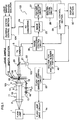
- Fig. 1 shows schematically a whole construction of a flow type particle image analysis apparatus, which is an embodiment of the present invention.
- this flow type particle image analysis apparatus consists of a flow cell 100, an image pickup section 101, a particle analysis section 102, a particle detection section 103, and a flow system control section 124.
- the image pickup section 101 includes a flash lamp drive circuit 1a, a flash lamp 1, a field lens 2, a visual field diaphragm 11, an aperture diaphragm 12, a microscope condenser lens 3, a microscope object lens 5 (used in common by the particle detection section 103), and a TV camera 8.
- the particle analysis section 102 has an A/D converter 24, an image memory 25, an image processing control circuit 26, a feature extraction circuit 27, an identification circuit 28, a section for analyzing number of particles 40, and a central control section 29.
- the section for analyzing number of particles 40 consists of a particle detection circuit 41, a counting circuit 42, and a particle detection logic circuit 43.
- the flow cell 100 consists of a parallel flow path portion 150, a stream restriction flow path portion 151, a measurement flow path portion 152, and a speed reducing flow path portion 153.
- the flow cell 100 is usually made of glass.
- the parallel flow path portion 150 extends from an inlet 117 to a junction portion with the stream restriction flow path portion 151.
- the cross-section thereof perpendicular to the flow direction of the liquid sample 111 is quadrilateral and a nozzle 114 is disposed in the neighborhood of the inlet 117 of the parallel flow path portion 150.
- the cross-sectional shape of this nozzle 114 is a rectangle, whose shorter side is in the thickness direction, which is almost identical to the pass direction of flash light described later and whose longer side is in the width direction, which is perpendicular both to the thickness direction and to the flow direction of the liquid sample.
- the intersection of the two diagonals of this rectangle is in accordance with the intersection of the two diagonals of the cross-sectional quadrilateral of the inlet 117 of the parallel flow path portion 150 and the rectangle is within the quadrilateral.
- the interior of this nozzle 114 constitutes the flow path of the liquid sample 111 and the exterior thereof is the flow path of the sheath solution 112.
- a sample guides 113 is mounted on the nozzle outlet 116 for maintaining the size of the flow of the liquid sample 111 in the width direction constant.
- This sample guide 113 consists of a pair of plate-shaped members, which are opposite to each other, putting the flow of the liquid sample 111 therebetween, and extends from the nozzle output 116 to a middle portion of the parallel flow path portion 150.
- the stream restriction flow path portion 151 extends from the junction portion with the parallel flow path portion 150 to the junction portion with the measurement flow path portion 152 and has a quadrilateral cross-section, the size of which remains unchanged in the width direction and decreases gradually towards the measurement flow path portion 152 in the thickness direction.
- the measurement flow path portion 152 extends from the junction portion with the stream restricting flow path portion 151 to the junction portion with the speed reducing flow path portion 153 and has a constant quadrilateral cross-section, in the middle portion of which there are disposed a particle detection region 80 and an image pickup region 90.
- the particle detection region 80 has an elongated shape extending in the width direction and having a length approximately equal to the width of the flow of the liquid sample.
- the image pickup region 90 is disposed on the downstream side of the particle detection region 80 and has a square shape, a side of which is approximately equal to the width of the flow of the liquid sample.
- the speed reducing flow path portion 153 extends from the junction portion with the measurement flow path portion 152 to an outlet 118 and has a quadrilateral cross-section, the size of which remains unchanged in the width direction and increases gradually along the flow direction of the liquid sample in the thickness direction.
- the liquid sample 111 containing the suspended particles and the sheath solution 112 flow at an inlet S1 into the parallel flow path portion 150.
- the liquid sample and the sheath solution flow therein according to the shape of the nozzle 114, a two-layered stream is formed, in which the liquid sample constitutes an inner layer, while the sheath solution forms an outer layer (covering layer).
- the guide 113 of this nozzle 114 suppresses disturbance of the liquid sample at the nozzle outlet 116. In this way it is possible to keep the width of the liquid sample almost at the width of the guide 113 from the nozzle outlet 116 to the outlet 118.
- the width of the liquid sample is kept constant and only the thickness is varied owing to the guide 113.
- the stream restriction flow path portion 151 When the liquids flow into the stream restriction flow path portion 151, the stream is restricted only in the thickness direction to form an ultra-flat sample flow approximately 200 to 300 ⁇ m wide and several ⁇ m to several tens of ⁇ m thick.
- the thickness of the ultra-flat sample flow in the measurement flow path portion 152 is adjusted, depending on the ratio in the flow rate between the liquid sample and the sheath solution. For example, in case where the flow rate of the ultra-flat sample flow is constant, when the flow rate of the sheath solution decreases, the width remains constant and the thickness of the ultra-flat sample flow increases and on the contrary if the flow rate of the sheath solution increases, the width remains constant and the thickness of the ultra-flat sample flow decreases.
- the width W0 remains unchanged and only the thickness is changed from T0 (state where the thickness is great) to T1 (state where the thickness is small) or from T1 to T0, as indicated in Figs. 3B and 3D.
- the particle detection section 103 includes a semiconductor laser light source 15, a collimator lens 16, a cylindrical lens 17, a reflection mirror 18, a micro-reflection-mirror 19, a microscope object lens 5, a beam splitter 20, a diaphragm 21, a light detection circuit 22, and a flash lamp emission control circuit 23.
- Laser light emitted by the semiconductor laser source 15 is transformed into a parallel laser light beam 14 by the collimator lens 16 and this laser light beam 14 is focused only in one direction by the cylindrical lens 17. This focused laser light beam illuminates the particle detection region 80 in the flow cell 100 through the reflection mirror 18 by the micro-reflection-mirror 19 disposed between the microscope lens 3 and the flow cell 100.
- the particle analysis section 102 converts image data signals outputted by the TV camera 8 into digital signals by means of an A/D converter 24 and stores data based thereon at predetermined addresses in the image memory 25 under control of the image processing control circuit 26.
- the data stored in the image memory 25 are read out under control of the image processing control circuit 26 and inputted to the feature extraction circuit 27 and the identification circuit 28 to be image-processed there. Results thus obtained are supplied to the central control section 29.
- particles are detected by the particle detection circuit 41 under particle detection signals from the central control section 29 and the light detection circuit 22 as well as a mode switching signal from the central control section 29 and subsequently the particles are counted by the counting circuit 42.
- Particles are detected by the particle detection circuit 41 according to a detection logic specified by the particle detection logic switching circuit 43 through electric signals from the light detection circuit 22.
- particle detection logic circuit 43 particle detection conditions are changed for each of the plurality of measurement modes by the central control section 29. Every time a particle is detected by the particle detection circuit 41, the content of the counting circuit 42 is increased by one and in this way at the end of the measurement it is possible to know the total number of the particles to be measured.
- Results thus obtained are sent to the central control section 29 and examined there on correspondence relation to the particle classification results obtained by the particle image processing. In this way final classification identification results are summarized. Results thus obtained are outputted to the display section 50 if necessary to be displayed. Further the particle detection signals of the particle detection circuit 41 are sent to the flash lamp lightening control circuit 23 to effect control of lightening the flash lamp or not and timing of the lightening.
- the concentration of particles in the liquid sample and the number of particles converted for the field of view are calculated on the basis of these measurement results and analysis results are returned to the central control section 29.
- the flow system control section 124 regulates the ratio in the flow rate between the liquid sample and the sheath solution flowing into the flow cell 100 according to signals from the central control section 29.
- Fig. 1 the liquid sample and the sheath solution flow through the flow cell 100 downward in the figure.
- Laser light coming from the semiconductor laser light source 15 passes through the collimator lens 16 to form a laser light beam 14.
- This laser light beam 14 illuminates the flow cell 100 through the cylindrical lens 17, the reflection mirror 18 and the micro-reflection-mirror 19.
- Laser light, which has passed through the flow cell 100 is reflected by the beam splitter 20 through the microscope object lens 5 and detected by the light detection circuit 22 through the diaphragm 21.
- a detection signal is sent from the light detection circuit 22 to the section for analyzing the number of particles 40.
- This detection signal is sent to the flash lamp emission control circuit 23 and the flash lamp 1 is lightened by the flash lamp drive circuit 1a under control of this circuit.
- Flash light from the flash lamp 1 passes through the lens 2 and illuminates the particle in the flow cell 100 through the visual field diaphragm 11, the aperture diaphragm 12 and the microscope condenser lens 3.
- An image of these illuminated particles is sent to the TV camera 8 through the microscope object lens 5.
- the image processing control circuit 26 supplies command signals to the image memory 25 and the section for analyzing the number of particles 40 according to information from the TV camera 8.
- image information obtained by the TV camera 8 is supplied to the image memory 25 through the A/D converter 24.
- the image information is sent from the image memory 25 to the central control section 29 through the feature extraction circuit 27 and the identification circuit 28.
- the central control section 29 controls operation of the section for analyzing the number of particles 40, the image processing control circuit 26 and the flow system control section 124, and at the same time makes the display section 50 display an image-processed image. Further the central control section 29 supplies control signals to the flow system control section 124 to vary the ratio of the flow rate of the liquid sample to the flow rate of the sheath solution and the thickness of the liquid sample in the flow cell 100, the width thereof remaining constant.
- the first measurement mode aims at particles, whose existence ratio, i.e. concentration is low
- the second measurement mode aims at particles, whose existence ratio, i.e. concentration is high.
- the second measurement mode even if all the particles in the sample are an object to be measured, influences of the particles, whose existence ratio is low, are small.
- Particle detection is carried out using a logic for particle detection in the first mode or one for the second mode depending on the measurement mode.
- Particle size information is used for the particle detection logic.
- the particle size information there are known two methods, by one of which a period of time required for a particle to pass through the particle detection system is used as an index, while by the other information of light scattered by the particle at irradiation with light is used.
- the magnitude of the period of time required for a particle to pass therethrough represents the particle size and the magnitude of scattering light also represents the particle size. Further there is a method, by which these two kinds of particle detection logics are used together.
- particle size is determined on the basis of the amplitude of fluorescence emitted from a particle.
- one-dimensional image sensor is implemented in a particle detection unit in order to obtain information of various shape of particles.
- a dyeing solution is added to the liquid sample, then the passing particle is detected on the basis of color level thereof, wherein the color level is varied, depending on the size of the particle to be measured.
- sedimentation components of urine are analyzed in the first measurement mode.
- information of particle size is used for particle detection.
- time required for a particle to pass through the particle detection unit or a amplitude of light scattering signals are measured.
- a threshold level of detection of the particle detection unit is set higher in the first measurement mode than in the second measurement mode. Since the concentration of particles is low, the flow speed and the thickness of the liquid sample are increased to increase amount of the liquid sample in the flow. In this way counted particles are increased then reproducibility of the measurement is improved.
- the second measurement mode particle components other than casts, which have smaller sizes but higher concentration, are treated.
- particle detection it is suitable to use particle size information and only particles of small size are detected. Since particles to be measured are red and white blood cells, concentration particle of is high thus satisfactory reproducibility can be obtained, even if the amount of the liquid sample is small. For this reason flow speed of the liquid sample can be low and thickness thereof can be small. The flow speed and the flow rate of the liquid sample are set under control of the flow control section 124. Even if the second measurement mode is used for measuring all kinds of passing particles in the liquid sample, since existence ratio of the other particles is small, they have no influences on the measurements, as described previously. Rather, in case where it is expected to detect at least one important particle, which is an object of the first measurement mode, it is preferable to consider all kinds of particles as object to be measured.
- red blood cells and white blood cells in blood are measured, there is a method, by which the blood cells are subjected to fluorescent dye and particle detection is carried out observing fluorescence from the blood cells.
- Fluorescent pigments such as acridine orange, make white blood cells emit fluorescence. On the contrary they make red blood cells emit almost no fluorescence.
- white blood cells may be treated in the first measurement mode, while red blood cells may be treated in the second measurement mode.
- Particle detection can be performed by detecting presence of a fluorescence signal. A period of time required for a white or red blood cell to pass through can be known by measuring light scattering signals. Since concentration of white blood cells in the liquid sample is very low, control of the flow rate, etc. of the liquid sample can be effected similarly to that described previously.
- a flow type image analysis apparatus in which a liquid sample, in which particles are suspended, is made flow through a flow cell, surrounded by a sheath solution, which is a cleaning solution; the liquid sample is irradiated with light to image particles contained therein by imaging means; an image thus picked up is subjected to image processing to effect classification of particles, since it comprises particle detection means disposed on the upstream side of an image pickup region, which determines particles to be measured at a plurality of measurement modes, and signals of a plurality of kinds of particles are distinguished, starting from particle detection signals thus obtained, to effect particle detection and image processing on a specified kind of particles distinguished in each of the measurement modes, particles in an image processed in each of the measurement modes are only the specified kind of particles previously determined.
- Particles can be detected according to particle judgement logic, by which presence or absence of a particle fit to either one of a plurality of measurement modes is judged by applying different particle presence or absence judgement logics for different measurement modes to the particle detection means.
- particle detection can be effected by using particle size information.
- a period of time for a particle to pass through the particle detection system, or information of light scattered by the particle at irradiation with light can be used as the particle size information.
- fluorescence information from the particle can be used.
- the particle detection system can be so constructed that in one of a plurality of measurement modes a specified kind of particles in the liquid sample are to be measured, while in another measurement mode all the kinds of particles in the liquid sample are to be measured, in the mode, in which all the kinds of particles are to be measured, even if specified particles are contained in the treated particles, this can be reflected in measurement results.
- concentration of the specified particles is low and in addition they are important particles, it is possible to reduce count missing of the important particles by having the particle detection system have a plurality of measurement modes.
- the light beam generation control means requires means for regulating drive start of the light beam generation means, depending on the flow speed of the liquid sample.
- the present embodiment since it is unnecessary to adjust magnification factor of the lens and light intensity, every time the measurement mode is switched over, no ND filter is required and neither regulation of the aperture diaphragm, projection lens and gain of the TV camera nor shading correction circuit is necessary. Therefore the construction is simple and the price is lowered. In addition, regulation operation can be carried out in a short time. Further, since optical image magnification factor doesn't vary at switching over the mode, it is unnecessary to vary the image pickup area and it is possible to simplify control operation of the apparatus.
- the present invention can be applied also to a case where a flow cell, in which the width of the liquid sample gradually increases or decreases, is used.
- the present invention can be applied also to a case where the image magnification factor varies.
Landscapes
- Chemical & Material Sciences (AREA)
- Dispersion Chemistry (AREA)
- Physics & Mathematics (AREA)
- Health & Medical Sciences (AREA)
- Life Sciences & Earth Sciences (AREA)
- Analytical Chemistry (AREA)
- Biochemistry (AREA)
- General Health & Medical Sciences (AREA)
- General Physics & Mathematics (AREA)
- Immunology (AREA)
- Pathology (AREA)
- Investigating Or Analysing Biological Materials (AREA)
Applications Claiming Priority (2)
| Application Number | Priority Date | Filing Date | Title |
|---|---|---|---|
| JP6086104A JPH07294414A (ja) | 1994-04-25 | 1994-04-25 | 粒子画像解析方法及び装置 |
| JP86104/94 | 1994-04-25 |
Publications (2)
| Publication Number | Publication Date |
|---|---|
| EP0679889A2 true EP0679889A2 (fr) | 1995-11-02 |
| EP0679889A3 EP0679889A3 (fr) | 1996-03-06 |
Family
ID=13877405
Family Applications (1)
| Application Number | Title | Priority Date | Filing Date |
|---|---|---|---|
| EP95105963A Withdrawn EP0679889A3 (fr) | 1994-04-25 | 1995-04-21 | Méthode et appareil pour analyse d'images de particules. |
Country Status (2)
| Country | Link |
|---|---|
| EP (1) | EP0679889A3 (fr) |
| JP (1) | JPH07294414A (fr) |
Cited By (9)
| Publication number | Priority date | Publication date | Assignee | Title |
|---|---|---|---|---|
| EP0791816A2 (fr) * | 1996-02-22 | 1997-08-27 | Hitachi, Ltd. | Procédé et appareil pour l'analyse des images des particules |
| EP0801295A1 (fr) * | 1996-04-03 | 1997-10-15 | TOA MEDICAL ELECTRONICS CO., Ltd. | Analyseur de particules |
| FR2777351A1 (fr) * | 1998-04-08 | 1999-10-15 | Hycel Diagnostics | Procede et dispositif de mesure de particules en suspension dans un liquide |
| US6087182A (en) * | 1998-08-27 | 2000-07-11 | Abbott Laboratories | Reagentless analysis of biological samples |
| EP1953527A2 (fr) | 2007-02-01 | 2008-08-06 | Sysmex Corporation | Analyseur d'échantillon et produit de programme informatique |
| CN103278654A (zh) * | 2007-02-01 | 2013-09-04 | 希森美康株式会社 | 标本分析仪及其控制系统 |
| US8906697B2 (en) | 1998-11-05 | 2014-12-09 | Chemometec A/S | Method for the assessment of particles and a system and device for use in the method |
| CN110068528A (zh) * | 2019-04-23 | 2019-07-30 | 中国石油大学(华东) | 检测装置和悬浮液中的颗粒检测方法 |
| CN112326538A (zh) * | 2015-03-31 | 2021-02-05 | 希森美康株式会社 | 尿分析系统、拍摄装置、细胞拍摄装置、尿分析方法、管理装置及信息处理方法 |
Families Citing this family (1)
| Publication number | Priority date | Publication date | Assignee | Title |
|---|---|---|---|---|
| JP4825033B2 (ja) * | 2006-03-31 | 2011-11-30 | シスメックス株式会社 | 尿分析装置 |
Citations (7)
| Publication number | Priority date | Publication date | Assignee | Title |
|---|---|---|---|---|
| DE3705876A1 (de) * | 1986-10-07 | 1988-04-14 | Toa Medical Electronics | Verfahren und vorrichtung fuer fliesscytometrie |
| US5088816A (en) * | 1989-09-19 | 1992-02-18 | Toa Medical Electronics Co., Ltd. | Process and apparatus for analyzing cells |
| EP0508688A2 (fr) * | 1991-04-05 | 1992-10-14 | Toa Medical Electronics Co., Ltd. | Procédé et dispositif pour l'analyse des particules |
| EP0556971A2 (fr) * | 1992-02-18 | 1993-08-25 | Hitachi, Ltd. | Appareil et procédé d'observation de particules dans un fluide |
| EP0564122A1 (fr) * | 1992-04-01 | 1993-10-06 | Toa Medical Electronics Co., Ltd. | Appareil d'analyse de particules |
| EP0649014A2 (fr) * | 1993-09-16 | 1995-04-19 | Toa Medical Electronics Co., Ltd. | Appareil d'analyse de particules |
| DE4437758A1 (de) * | 1993-10-21 | 1995-04-27 | Hitachi Ltd | Bildanalyseverfahren und -vorrichtung für Strömungspartikel |
-
1994
- 1994-04-25 JP JP6086104A patent/JPH07294414A/ja active Pending
-
1995
- 1995-04-21 EP EP95105963A patent/EP0679889A3/fr not_active Withdrawn
Patent Citations (7)
| Publication number | Priority date | Publication date | Assignee | Title |
|---|---|---|---|---|
| DE3705876A1 (de) * | 1986-10-07 | 1988-04-14 | Toa Medical Electronics | Verfahren und vorrichtung fuer fliesscytometrie |
| US5088816A (en) * | 1989-09-19 | 1992-02-18 | Toa Medical Electronics Co., Ltd. | Process and apparatus for analyzing cells |
| EP0508688A2 (fr) * | 1991-04-05 | 1992-10-14 | Toa Medical Electronics Co., Ltd. | Procédé et dispositif pour l'analyse des particules |
| EP0556971A2 (fr) * | 1992-02-18 | 1993-08-25 | Hitachi, Ltd. | Appareil et procédé d'observation de particules dans un fluide |
| EP0564122A1 (fr) * | 1992-04-01 | 1993-10-06 | Toa Medical Electronics Co., Ltd. | Appareil d'analyse de particules |
| EP0649014A2 (fr) * | 1993-09-16 | 1995-04-19 | Toa Medical Electronics Co., Ltd. | Appareil d'analyse de particules |
| DE4437758A1 (de) * | 1993-10-21 | 1995-04-27 | Hitachi Ltd | Bildanalyseverfahren und -vorrichtung für Strömungspartikel |
Cited By (31)
| Publication number | Priority date | Publication date | Assignee | Title |
|---|---|---|---|---|
| EP0791816A2 (fr) * | 1996-02-22 | 1997-08-27 | Hitachi, Ltd. | Procédé et appareil pour l'analyse des images des particules |
| EP0791816A3 (fr) * | 1996-02-22 | 1998-05-06 | Hitachi, Ltd. | Procédé et appareil pour l'analyse des images des particules |
| US6317511B1 (en) | 1996-02-22 | 2001-11-13 | Hitachi, Ltd. | Method and apparatus for particle image analysis using flow cell |
| EP0801295A1 (fr) * | 1996-04-03 | 1997-10-15 | TOA MEDICAL ELECTRONICS CO., Ltd. | Analyseur de particules |
| US5831723A (en) * | 1996-04-03 | 1998-11-03 | Toa Medical Electronics Co., Ltd. | Particle analyzer |
| FR2777351A1 (fr) * | 1998-04-08 | 1999-10-15 | Hycel Diagnostics | Procede et dispositif de mesure de particules en suspension dans un liquide |
| US6089078A (en) * | 1998-04-08 | 2000-07-18 | Hycel Diagnostics | Process and device for measuring particles in suspension in a liquid |
| US6087182A (en) * | 1998-08-27 | 2000-07-11 | Abbott Laboratories | Reagentless analysis of biological samples |
| US6365109B1 (en) | 1998-08-27 | 2002-04-02 | Abbott Laboratories | Reagentless analysis of biological samples |
| US6426045B1 (en) | 1998-08-27 | 2002-07-30 | Abbott Laboratories | Reagentless analysis of biological samples |
| US6773922B2 (en) | 1998-08-27 | 2004-08-10 | Abbott Laboratories | Reagentless analysis of biological samples |
| US8906697B2 (en) | 1998-11-05 | 2014-12-09 | Chemometec A/S | Method for the assessment of particles and a system and device for use in the method |
| CN103278654B (zh) * | 2007-02-01 | 2014-10-01 | 希森美康株式会社 | 标本分析仪及其控制系统 |
| US11921106B2 (en) | 2007-02-01 | 2024-03-05 | Sysmex Corporation | Sample analyzer and computer program product |
| EP1953527A3 (fr) * | 2007-02-01 | 2013-06-05 | Sysmex Corporation | Analyseur d'échantillon et produit de programme informatique |
| EP1953527A2 (fr) | 2007-02-01 | 2008-08-06 | Sysmex Corporation | Analyseur d'échantillon et produit de programme informatique |
| EP1953527B1 (fr) | 2007-02-01 | 2017-01-11 | Sysmex Corporation | Analyseur d'échantillon et produit de programme informatique |
| EP3153841A1 (fr) * | 2007-02-01 | 2017-04-12 | Sysmex Corporation | Analyseur d'échantillon et produit de programme informatique |
| US9933414B2 (en) | 2007-02-01 | 2018-04-03 | Sysmex Corporation | Sample analyzer and computer program product |
| US10151746B2 (en) | 2007-02-01 | 2018-12-11 | Sysmex Corporation | Sample analyzer and computer program product |
| US10209244B2 (en) | 2007-02-01 | 2019-02-19 | Sysmex Corporation | Sample analyzer and computer program product |
| EP1953527B2 (fr) † | 2007-02-01 | 2024-01-03 | Sysmex Corporation | Analyseur d'échantillon et produit de programme informatique |
| US10401351B2 (en) | 2007-02-01 | 2019-09-03 | Sysmex Corporation | Sample analyzer and computer program product |
| US10401350B2 (en) | 2007-02-01 | 2019-09-03 | Sysmex Corporation | Sample analyzer and computer program product |
| EP3680643A1 (fr) * | 2007-02-01 | 2020-07-15 | Sysmex Corporation | Analyseur d'échantillon et produit programme informatique |
| CN103278654A (zh) * | 2007-02-01 | 2013-09-04 | 希森美康株式会社 | 标本分析仪及其控制系统 |
| EP4027130A1 (fr) * | 2007-02-01 | 2022-07-13 | Sysmex Corporation | Analyseur d'échantillon et produit programme informatique |
| US11415575B2 (en) | 2007-02-01 | 2022-08-16 | Sysmex Corporation | Sample analyzer and computer program product |
| EP4151985A1 (fr) * | 2007-02-01 | 2023-03-22 | Sysmex Corporation | Analyseur d'échantillons |
| CN112326538A (zh) * | 2015-03-31 | 2021-02-05 | 希森美康株式会社 | 尿分析系统、拍摄装置、细胞拍摄装置、尿分析方法、管理装置及信息处理方法 |
| CN110068528A (zh) * | 2019-04-23 | 2019-07-30 | 中国石油大学(华东) | 检测装置和悬浮液中的颗粒检测方法 |
Also Published As
| Publication number | Publication date |
|---|---|
| EP0679889A3 (fr) | 1996-03-06 |
| JPH07294414A (ja) | 1995-11-10 |
Similar Documents
| Publication | Publication Date | Title |
|---|---|---|
| US5594544A (en) | Flow type particle image analyzing method and apparatus | |
| JP3213334B2 (ja) | 尿中の細胞分析装置 | |
| US6317511B1 (en) | Method and apparatus for particle image analysis using flow cell | |
| EP0681177B1 (fr) | Procédé et dispositif de classification et de numérisation de cellules | |
| JP3098273B2 (ja) | 尿中の細胞分析装置 | |
| US8538119B2 (en) | Particle image analysis method and apparatus | |
| JP2002516982A (ja) | 抗凝固全血静止サンプルの分析 | |
| JPH05180751A (ja) | 粒子画像分析装置 | |
| EP0679889A2 (fr) | Méthode et appareil pour analyse d'images de particules | |
| CA2487233A1 (fr) | Methode et appareil pour la mesure de particules au moyen de l'imagerie optique | |
| US7217937B2 (en) | Automatic identification of suspended particles | |
| JPH08210961A (ja) | フロー式粒子画像解析方法および装置 | |
| JP3282458B2 (ja) | フロー式粒子画像解析方法および装置 | |
| JPH06138120A (ja) | 尿沈渣検査装置 | |
| JP2826448B2 (ja) | フロー式粒子画像解析方法およびフロー式粒子画像解析装置 | |
| JP3213333B2 (ja) | 尿中の細胞分析装置および方法。 | |
| JPH09311102A (ja) | フロー式粒子画像解析方法および装置 | |
| JP3494559B2 (ja) | フロー式粒子画像解析方法及び装置 | |
| JP2002062251A (ja) | フロー式粒子画像解析方法及び装置 | |
| JP2002277381A (ja) | 粒子分析装置 | |
| JPH06288895A (ja) | 粒子分析装置 | |
| JP2000046723A (ja) | 血小板機能検査方法 | |
| JPH08145872A (ja) | フロー式粒子画像解析方法および装置 | |
| JPH0961339A (ja) | フロ−式粒子画像解析方法および装置 | |
| EP1070952A2 (fr) | Procédé et moyens pour la mesure des particules |
Legal Events
| Date | Code | Title | Description |
|---|---|---|---|
| PUAI | Public reference made under article 153(3) epc to a published international application that has entered the european phase |
Free format text: ORIGINAL CODE: 0009012 |
|
| 17P | Request for examination filed |
Effective date: 19950421 |
|
| AK | Designated contracting states |
Kind code of ref document: A2 Designated state(s): DE FR GB |
|
| PUAL | Search report despatched |
Free format text: ORIGINAL CODE: 0009013 |
|
| AK | Designated contracting states |
Kind code of ref document: A3 Designated state(s): DE FR GB |
|
| 17Q | First examination report despatched |
Effective date: 19990325 |
|
| STAA | Information on the status of an ep patent application or granted ep patent |
Free format text: STATUS: THE APPLICATION HAS BEEN WITHDRAWN |
|
| 18W | Application withdrawn |
Withdrawal date: 19990921 |