EP0679569B1 - Schalteinrichtung für ein Wechselgetriebe in Mehrgangnaben für Fahrräder - Google Patents
Schalteinrichtung für ein Wechselgetriebe in Mehrgangnaben für Fahrräder Download PDFInfo
- Publication number
- EP0679569B1 EP0679569B1 EP95100407A EP95100407A EP0679569B1 EP 0679569 B1 EP0679569 B1 EP 0679569B1 EP 95100407 A EP95100407 A EP 95100407A EP 95100407 A EP95100407 A EP 95100407A EP 0679569 B1 EP0679569 B1 EP 0679569B1
- Authority
- EP
- European Patent Office
- Prior art keywords
- change
- cam
- speed gear
- pawl
- gear according
- Prior art date
- Legal status (The legal status is an assumption and is not a legal conclusion. Google has not performed a legal analysis and makes no representation as to the accuracy of the status listed.)
- Expired - Lifetime
Links
- 241001272720 Medialuna californiensis Species 0.000 claims 1
- 230000036316 preload Effects 0.000 claims 1
- 230000000284 resting effect Effects 0.000 claims 1
- 230000008878 coupling Effects 0.000 abstract description 6
- 238000010168 coupling process Methods 0.000 abstract description 6
- 238000005859 coupling reaction Methods 0.000 abstract description 6
- 238000004519 manufacturing process Methods 0.000 description 3
- 230000002093 peripheral effect Effects 0.000 description 3
- 239000000969 carrier Substances 0.000 description 2
- 238000006073 displacement reaction Methods 0.000 description 1
- 238000009434 installation Methods 0.000 description 1
- 238000000034 method Methods 0.000 description 1
- 239000000725 suspension Substances 0.000 description 1
Images

Classifications
-
- B—PERFORMING OPERATIONS; TRANSPORTING
- B62—LAND VEHICLES FOR TRAVELLING OTHERWISE THAN ON RAILS
- B62M—RIDER PROPULSION OF WHEELED VEHICLES OR SLEDGES; POWERED PROPULSION OF SLEDGES OR SINGLE-TRACK CYCLES; TRANSMISSIONS SPECIALLY ADAPTED FOR SUCH VEHICLES
- B62M11/00—Transmissions characterised by the use of interengaging toothed wheels or frictionally-engaging wheels
- B62M11/04—Transmissions characterised by the use of interengaging toothed wheels or frictionally-engaging wheels of changeable ratio
- B62M11/14—Transmissions characterised by the use of interengaging toothed wheels or frictionally-engaging wheels of changeable ratio with planetary gears
- B62M11/16—Transmissions characterised by the use of interengaging toothed wheels or frictionally-engaging wheels of changeable ratio with planetary gears built in, or adjacent to, the ground-wheel hub
-
- F—MECHANICAL ENGINEERING; LIGHTING; HEATING; WEAPONS; BLASTING
- F16—ENGINEERING ELEMENTS AND UNITS; GENERAL MEASURES FOR PRODUCING AND MAINTAINING EFFECTIVE FUNCTIONING OF MACHINES OR INSTALLATIONS; THERMAL INSULATION IN GENERAL
- F16H—GEARING
- F16H3/00—Toothed gearings for conveying rotary motion with variable gear ratio or for reversing rotary motion
- F16H3/44—Toothed gearings for conveying rotary motion with variable gear ratio or for reversing rotary motion using gears having orbital motion
- F16H3/62—Gearings having three or more central gears
- F16H3/66—Gearings having three or more central gears composed of a number of gear trains without drive passing from one train to another
- F16H3/663—Gearings having three or more central gears composed of a number of gear trains without drive passing from one train to another with conveying rotary motion between axially spaced orbital gears, e.g. a stepped orbital gear or Ravigneaux
Definitions
- the invention relates to a switching device for a change gear in multi-speed hubs for bicycles according to the generic term of claim 1.
- a switching device of a similar design is from the DE 24 58 871 known, where also by control movements tubular switching element effective in one direction Couplings can be switched on and off in relation to the fixed shaft are.
- tubular switching element effective in one direction Couplings can be switched on and off in relation to the fixed shaft are.
- gear hub consisting of many different parts the main obstacle to the rational production of the same.
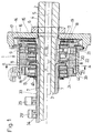
- the switching device 1 is a switching device 1 for a change gear described in multi-gear hubs for bicycles, the concentrically around the end of a hub axle 2 is arranged.
- the switching device 1 constitutes an assembly unit on the hub axle 2 and is axially on this pushed on and by a nut 6 and a snap ring 46 secured.
- the switching device 1 comprises one Fixed cone 15, a pulley 14, a guide plate 17, one first cam ring 21, a second cam ring 22, one third cam ring 23, a fourth cam ring 24, four Control disks 18, four cam levers 9, four bearing disks 11, and at least one thrust washer 13.
- FIG. 1 is a switching device 1 for a change gear described in multi-gear hubs for bicycles, the concentrically around the end of a hub axle 2 is arranged.
- the switching device 1 constitutes an assembly unit on the hub axle 2 and is axially on this pushed on and by a nut 6 and a snap ring 46 secured.
- the switching device 1 comprises one Fixed cone 15,
- Switch cam rods 7 are visible, which are semicircular in the longitudinal grooves 3 of the hub axis 2 are stored and axially parallel on the outer circumference of the hub axle 2 of the switching device 1 in the direction of the change gear of the multi-speed hub.
- a hook 8 is formed, which is bent at right angles and by two Carriers 10 is performed.
- the switching cam rods 7 transmit the control movements from the switching device 1 in the change gear of the hub, not shown here, which in several Levels transverse to the hub axis 2 has at least two sun gears 29, 29 ', in which pivotable pawls 28 are arranged for the purpose of forming a a direction of rotation acting against a web 30 radially inward are sprung by means of a spring 45, the webs 30 being axially parallel on the outer circumference of the hub axis 2 and the flanks of the webs 30 extend from the longitudinal grooves 3 be formed. All webs 30 are of the same height and form with their peripheral surface 47 the outer diameter of the hub axle 2. Between the contour of the longitudinal grooves 3 and the circumferential surface 47 is formed on a slope 39, in particular on the Side of the engagement of the pawl 28 is attached.
- the switching cam rod 7 has a first radially outward over its entire length Profile 33, which is roof-shaped, the ridge of the roof is the center of the radius for the contour of the longitudinal groove 3.
- Profile 33 which is roof-shaped, the ridge of the roof is the center of the radius for the contour of the longitudinal groove 3.
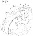
- 3 shows the constellation of Pawl 28 to the web 30, where it is made clear that the pawl 28 when rotating in the Direction of rotation 32 can not come to rest on the web, but rather from this is rejected.
- the switching cam rod 7 for switching the Couplings in the Sun gears 29, 29 'in the change gear of the hub by one Angle 31 can be pivoted, with a first switching position 37 of the hook 8 as the one extreme position and a second Switch position 38 of the hook 8 as the other extreme position is defined.
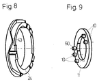
- Fig. 9 reached on the control disc 18 in the axial direction are arranged pointing and take the hook 8 in the middle. When this control disk 18 rotates, the hook 8 is moved around the said angle 31 twisted.
- FIGS. 4 and 5 The rotation of the first profile 33 of the switching cam rod 7 is illustrated with FIGS. 4 and 5, where the pawl 28 in the first switching position 37 acc. Fig. 4 when rotating in the direction of rotation 32 on the first profile 33 to the first of the first profile 33 runs up and after passing the ridge along the second roof half of the first profile 33 steered over the web 30 becomes. 5, the pawl 28 is also up to First of the first profile 33 steered, but without radial swivel in as the contact surface of the first roof half of the first profile 33 in approximately the peripheral surface 47 adapts the hub axle 2.
- the pawl 28 When turning further in the direction of rotation 32, the pawl 28 can then on the web 30 do not support because of the ridge on the long side of the Pawl 28 slides along and the edge of the pawl 28 at most merges with slope 39, whereby the pawl 28 is rejected.
- both extreme positions of the first Profile 33 reject the pawl 28, which makes a transverse to Slideway of the pawl 28 arranged on the hub axis 2 Switching element is found, which without major constructive Precautions can be taken through any number of sun gear levels is a sun gear up to the plane, for example 29 ', which with a second profile 34 once with the Hub axle 2 is to be coupled and released once.
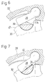
- the switching cam rod 7 second profile 34 allows namely in the first Switch position 37 acc. Fig. 6 that the pawl 28 when rotating of the sun gear 29 'in the direction of rotation 32 in that shown there Position of the second profile 34 is rejected.
- the already pawl 28 is partially immersed in the longitudinal groove 3 due to the radially outward path of the second profile 34 again lifted and steered over the web 30. Only after pivoting the switching cam rod 7 around the Angle 31 becomes the second profile 34 for bevelling slopes the pawl 28 in the longitudinal groove 3 against the web 30 acc. Fig. 7.
- the hub axis points 2 eight longitudinal grooves 3 and a corresponding number of switch cam rods 7 on. It would now be possible to close eight sun gear planes operate, with one revolution of the respective sun gear always a second profile 34 would come to bear. But since this too would lead to relatively high backlash angles in the drive train, were to be switched in this embodiment Coupling in the desired sun gear level always two opposite Switch cam rods 7 in an identical design arranged opposite each other, whereby each sun gear 29, 29 ', twice per revolution is given the opportunity to oppose the Support hub axle 2 when controlling from outside this requires. It can therefore be seen that with this arrangement four sun gear levels can be operated.
- the switching device 1 transmits the control movement of the Cyclist in the swivel movements of the shift cam rods 7 as follows: With a switch not shown here pulled on a rope 27 and so the control movement in the Rope pulley 14 initiated, on which the rope 27 is wound with its end connected to the pulley 14 is. A return spring 16 brings the rope pulley 14 when it wears off the tax movement back to its original position. With the pulley 14 are the first cam ring 21, the second Cam ring 22, the third cam ring 23 and the fourth cam ring 24 connected via at least one screw 26, whereby a tubular housing with four cam tracks 42 is formed becomes.
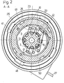
- cam lever 9 there is a cam lever within each cam track 42 9 arranged, which with its crescent-curved Shape in the remaining annulus between hub axis 2 and the respective cam ring, here 23, is inserted.
- the cam lever 9 is pivotally mounted by means of a bolt 48 and points at the outer radius of the curvature approximately in the central area a cam 41 which interacts with the cam track 42 and gladly.
- Fig. 2 allows the cam lever 9 after to pivot outside as soon as the cam track 42 with her rotates enlarged radius over the cam 9. To this Way gives way to a surface 49 which is opposite to the bolt 48 End of the cam lever 9 is attached, back and gives the carriers 10, the surface 49 in contact stand, the possibility to follow the surface 49 and the hook 8 from the first switching position 37 to the second switching position 38 to take with you.
- the bolt 48 supports the cam lever 9 on the bearing washer 11, which 12 in the longitudinal grooves 3 rotatably connected to the hub axle 2 is.
- the drivers 10 are connected to the control disk 18, the control disk 18 also has a driving pin 50, in which a spring 19 is hung, the one Traction between him and a spring suspension 20, which the bearing disc 11 is arranged generated. In this way is a relative rotation of the bearing plate 11 and Control disc 18 is generated, which occurs when the surface 49 of the cam lever 9 retreats. So it is through the on the rope 27 initiated control movement a rotation of all Cam rings 21 ... 24 causes everyone on his Act cam lever 9 and the surfaces 49, the driver 10, the respective hook 8 of the respective switching cam rod 70 the second profile 34 for the pawl 28 of each sun gear level for precise switching processes by switching on and off of the clutches.
- the switching sleeve 25 is for this reason axially displaceable and secured against twisting and is by the slider 44 according to the axial curve 43 back and forth, which at the appropriate Interpretation of the cam tracks 42 and the curves 43 to an advantageous coordinated selection of many gear levels which can be graded at low cost and in the right order are switchable.
Landscapes
- Engineering & Computer Science (AREA)
- General Engineering & Computer Science (AREA)
- Mechanical Engineering (AREA)
- Chemical & Material Sciences (AREA)
- Combustion & Propulsion (AREA)
- Transportation (AREA)
- Structure Of Transmissions (AREA)
Description
- Fig. 1
- eine Schalteinrichtung mit einem Festkonus, einer Seilrolle, vier Nockenringen sowie mehreren Schaltelementen auf einer Nabenachse im Schnitt auf einer Ebene koaxial zu dieser Nabenachse;
- Fig. 2
- die Schalteinrichtung im Schnitt auf einer Ebene quer zur Nabenachse mit den Schaltelementen, umfassend einen Nockenhebel, eine Schaltnockenstange, einen Nockenring sowie eine Schaltbuchse;
- Fig. 3
- einen Teilschnitt quer zur Nabenachse mit einem Sonnenrad und der Schaltnockenstange, die mit einem ersten Profil eine Klinke aushebt.
- Fig. 4
- den Teilschnitt gemäß Fig. 3, mit der Schaltnockenstange, dem Sonnenrad und der vom ersten Profil ausgehobenen Klinke;
- Fig. 5
- den Teilschnitt nach Fig. 4 mit ebenfalls ausgehobener Klinke auf dem gedrehten ersten Profil der Schaltnockenstange;
- Fig. 6
- den Teilschnitt nach Fig. 4 mit der von einem zweiten Profil der Schaltnockenstange ausgehobene Klinke;
- Fig. 7
- den Teilschnitt nach Fig. 4 mit der Klinke im Eingriff mit einem Steg der Nabenachse bei verschwenktem zweiten Profil der Schaltnockenstange;
- Fig. 8
- ein Nockenring mit einer axialen Kurve zur Steuerung einer Gleiteinrichtung einer Schaltbuchse perspektivisch dargestellt;
- Fig. 9
- eine Lagerscheibe mit Mitnehmern zur Steuerung der Schaltnockenstangen in perspektivischer Darstellung.
Claims (21)
- Wechselgetriebe in einer Mehrgangnabe für ein Fahrrad, umfassend eine Schalteinrichtung (1) auf einer Nabenachse (2) zum Wechseln der Gangstufen in dem als Planetengetriebe ausgeführten Wechselgetriebe über mindestens eine Klinke (28) als in einer Drehrichtung wirkende Kupplung in mindestens einem Sonnenrad (29,29') um ein das Wechselgetriebe umgebendes und mit deren in Antriebsverbindung bringbares Laufrad mit verschiedenen Drehzahlen anzutreiben, wobei die Schalteinrichtung (1) an einem Ende der Nabenachse (2) benachbart zu einem Festkonus (15) angeordnet ist und eine durch eine Rückholfeder (16) in einer Drehrichtung angefederte Seilrolle (14) mit einem auf diese aufwickelbaren Seil (27) aufweist,
dadurch gekennzeichnet,
daß die Schalteinrichtung (1) zur Steuerung der Kupplungen in den Sonnenrädern (29,29') mindestens eine Schaltnockenstange (7) umfaßt, die in einer am Außenumfang der Nabenachse (2) achsparallel angeordneten und jeder Schaltnockenstange (7) zugeordneten Längsnut (3) drehbeweglich geführt ist, wobei jede Klinke (28) von jeweils einer von der Schalteinrichtung (1) verdrehbaren Schaltnockenstange (7) ein- und aussteuerbar ist. - Wechselgetriebe nach Anspruch 1,
dadurch gekennzeichnet,
daß die Klinken (28) in den Sonnenrädern (29) schwenkbeweglich unter Vorspannung einer Klinkenfeder (45) gelagert sind und sich gegen Stege (30) abstützten können, die sich zwischen den Längsnuten (3) erheben. - Wechselgetriebe nach Anspruch 1 oder 2,
dadurch gekennzeichnet,
daß die Längsnuten (3) ein halbkreisförmiges Profil haben, in welchem sich die Schaltnockenstangen (7) mit ebenfalls halbkreisförmigen Profil um einen Winkel (31) drehen können, wodurch in den beiden Endlagen des Winkels (31) jeweils eine erste Schaltposition (37) und eine zweite Schaltposition (38) erreicht wird. - Wechselgetriebe nach einem der Ansprüche 2 oder 3,
dadurch gekennzeichnet,
daß die Schaltnockenstange (7) auf ihrer Erstreckung in der Längsnut (3) zwei Profile (33 und 34) aufweist, von denen das erste Profil (33) die Klinke (28) in beiden Schaltpositionen (37 und 38) der Schaltnockenstange (7) dauernd ausgehoben hält, das zweite Profil (34) die Klinke (28) in der ersten Schaltposition (37) der Schaltnockenstange (7) vom Steg (30) abweist, in der zweiten Schaltposition (38) der Schaltnockenstange (7) der Klinke (28) aber den Weg zum Steg (30) freigibt. - Wechselgetriebe nach einem der Ansprüche 2 bis 4,
dadurch gekennzeichnet,
daß das erste Profil (33) in einer Ebene quer zur Drehachse der Schaltnockenstange (7) eine Dachform beschreibt, dessen First einen Radius (35) um die Drehachse der Schaltnockenstange (7) beschreibt und dessen beide Dachhälften zueinander etwa einen Winkel bilden, der sich aus der Differenz zwischen 180° und dem Drehwinkel (31) der Schaltnockenstange (7) ergibt. - Wechselgetriebe nach einem der Ansprüche 2 bis 5,
dadurch gekennzeichnet,
daß der Steg (30) eine Schräge (39) aufweist, die die Klinke (28) hilfsweise ablenkt sofern eine Überdeckung zwischen der auf dem Steg auflaufenden Kante der Klinke (28) und dem Steg (30) entsteht. - Wechselgetriebe nach einem der Ansprüche 2 bis 5,
dadurch gekennzeichnet,
daß die auf dem Steg (30) auflaufende Kante der Klinke (28) eine Schräge oder eine Rundung aufweist, die in die nach radial innen weisende Längsseite der Klinke (28) überleitet und die Klinke (28) am Steg (30) und/oder an dessen Schräge (39) abweist. - Wechselgetriebe nach einem der Ansprüche 4 bis 7,
dadurch gekennzeichnet,
daß das zweite Profil (34) einer geraden Fläche entspricht, die dem Querschnitt der Schaltnockenstange (7) eine Halbmondform verleiht und die Klinke (28) in der ersten Schaltposition (37) vom Steg (30) abweist, in der zweiten Schaltposition (38) jedoch den Eingriff gegen den Steg (30) auf der Nabenachse (2) erlaubt. - Wechselgetriebe nach einem der Ansprüche 2 bis 8,
dadurch gekennzeichnet,
daß der Klinke (28) eines jeden Sonnenrades (29,29') mindestens eine Schaltnockenstange (7) zugeordnet ist, wodurch die Klinke (28) auf der Nabenachse (2) bei ihrem Umlauf abwechselnd einen Steg (30) und eine Schaltnockenstange (7) überfährt. - Wechselgetriebe nach einem der Ansprüche 4 bis 9,
dadurch gekennzeichnet,
daß die Schaltnockenstange (7) das erste Profil (33) dort aufweist, wo ein Eingriff der Klinke (28) in keiner der möglichen Schaltpositionen (7 und 38) der Schaltnockenstange (7) stattfinden soll, und daß die Schaltnockenstange (7) das zweite Profil (34) dort aufweist, wo die Klinke (28) in der ersten Schaltposition (37) abgewiesen wird, wenn sie sich in einer Drehrichtung (32) bewegt, und daß die Klinke (28) in der zweiten Schaltposition (38) zum Eingriff mit dem Steg (30) gelangt, wenn sie sich in der Drehrichtung (32) bewegt. - Wechselgetriebe nach einem der Ansprüche 1 bis 10,
dadurch gekennzeichnet,
daß die Schaltnockenstange (7) einen Haken (8) aufweist, der rechtwinklig von der Schaltnockenstange (7) abgebogen und von zwei Mitnehmern (10), die auf einer Steuerscheibe (18) angeordnet sind, beidseitig geführt wird. - Wechselgetriebe nach einem der Ansprüche 1 bis 11,
dadurch gekennzeichnet,
daß am Umfang der Nabenachse (2) eine durch zwei teilbare Anzahl von Längsnuten (3) angeordnet ist, wobei jeweils die sich um 180° gegenüberliegenden Schaltnockenstangen (7) identisch sind. - Wechselgetriebe nach einem der Ansprüche 11 oder 12,
dadurch gekennzeichnet,
daß der Haken (8) einer jeden Schaltnockenstange (7) die Steuerung jeweils eines Sonnenrades (29,29') übernimmt, und daß somit jeweils ein Haken (8) mit den Mitnehmern (10) auf einer Lagerscheibe (11), einer Steuerscheibe (18), einem Nockenhebel (9) und einem zugehörigen Nockenring (hier 23) jeweils als Schalteinheit der Schaltnockenstange (7) zugeordnet ist. - Wechselgetriebe nach Anspruch 13,
dadurch gekennzeichnet,
daß jeder Haken (8) axial gesehen zwischen der Steuerscheibe (18) und der Lagerscheibe (11) angeordnet ist, wobei die Steuerscheibe (18) die von außen wirkende Steuerbewegung auf den Haken (8) über seine Mitnehmer (10) überträgt, während die Lagerscheibe (11) über mindestens eine Führungsnase (12) mit der Nabenachse (2) drehfest verbunden ist. - Wechselgetriebe nach einem der Ansprüche 13 oder 14,
dadurch gekennzeichnet,
daß die Steuerscheibe (18) und die Lagerscheibe (11) gegeneinander in einer Drehrichtung mittels einer Feder (19) vorgespannt sind. - Wechselgetriebe nach einem der Ansprüche 13 bis 15,
dadurch gekennzeichnet,
daß an der Lagerscheibe (11) mindestens ein Nockenhebel (9) angeordnet ist, der nach radial außen einen Nocken (41) aufweist, der mit einer Nockenbahn (42) zu-sammenwirkt, die in jedem von mehreren Nockenringen (21...24) angeordnet ist. - Wechselgetriebe nach Anspruch 16,
dadurch gekennzeichnet,
daß die Seilrolle (14) mit dem ersten Nockenring (21), dieser mit dem zweiten Nockenring (22), dieser mit dem dritten Nockenring (23) und dieser wiederum mit dem vierten Nockenring (24) koaxial zu einem rohrförmigen Schaltelement verbunden sind. - Wechselgetriebe nach einem der Ansprüche 16 oder 17,
dadurch gekennzeichnet,
daß mindestens ein Nockenring (hier 24) an einer Planfläche eine in axialer Richtung profilierte Kurve (43) aufweist, die mit einer Gleiteinrichtung (44) zusammenwirkt, die mit einer Schaltbuchse (25) verbunden ist, wobei auf die gegen Drehung gesicherte Schaltbuchse (25) eine axiale Bewegung übertragbar ist. - Wechselgetriebe nach Anspruch 18,
dadurch gekennzeichnet,
daß die Schaltbuchse (25) die Nockenringe (21...24) rohrförmig umschließt. - Wechselgetriebe nach einem der Ansprüche 18 oder 19,
dadurch gekennzeichnet,
daß die Schaltbuchse 25) auf mindestens einem der vier Nockenringe (21...24) drehbar gelagert ist. - Wechselgetriebe nach einem der Ansprüche 18 bis 20,
dadurch gekennzeichnet,
daß die Schaltbuchse (25) eine Schräge (36) aufweist, die bei axialer Bewegung der Schaltbuchse 25) eine Klinke (40) im Wechselgetriebe der Mehrgangnabe ausheben oder einklinken kann.
Applications Claiming Priority (2)
| Application Number | Priority Date | Filing Date | Title |
|---|---|---|---|
| DE4415266A DE4415266C1 (de) | 1994-04-30 | 1994-04-30 | Schalteinrichtung für ein Wechselgetriebe in Mehrgangnaben für Fahrräder |
| DE4415266 | 1994-04-30 |
Publications (2)
| Publication Number | Publication Date |
|---|---|
| EP0679569A1 EP0679569A1 (de) | 1995-11-02 |
| EP0679569B1 true EP0679569B1 (de) | 1999-03-17 |
Family
ID=6516960
Family Applications (1)
| Application Number | Title | Priority Date | Filing Date |
|---|---|---|---|
| EP95100407A Expired - Lifetime EP0679569B1 (de) | 1994-04-30 | 1995-01-13 | Schalteinrichtung für ein Wechselgetriebe in Mehrgangnaben für Fahrräder |
Country Status (4)
| Country | Link |
|---|---|
| US (1) | US5556354A (de) |
| EP (1) | EP0679569B1 (de) |
| AT (1) | ATE177695T1 (de) |
| DE (2) | DE4415266C1 (de) |
Cited By (1)
| Publication number | Priority date | Publication date | Assignee | Title |
|---|---|---|---|---|
| EP1289827B2 (de) † | 2000-05-27 | 2009-04-22 | Sunrace Sturmey-Archer Inc. | Mehrgangnabe |
Families Citing this family (18)
| Publication number | Priority date | Publication date | Assignee | Title |
|---|---|---|---|---|
| US6120409A (en) * | 1996-10-02 | 2000-09-19 | Hawkins; Tranel | Planetary gear shifting hub for a bicycle |
| US5924950A (en) * | 1997-10-06 | 1999-07-20 | Pusic; Pavo M | Even increment, non-overlapping bicycle transmission |
| JP3470654B2 (ja) * | 1999-09-29 | 2003-11-25 | 富士電機株式会社 | 選択作動装置 |
| DE10019989A1 (de) * | 2000-04-22 | 2001-10-25 | Sram De Gmbh | Freilaufkupplung mit zwangsgesteuerter Sperrklinke |
| DE10030959A1 (de) * | 2000-06-24 | 2002-01-03 | Sram De Gmbh | Mehrgangschaltnabe |
| US6875150B2 (en) | 2001-12-27 | 2005-04-05 | Shimano, Inc. | Multiple piece planet gear carrier for a bicycle hub transmission |
| US6641500B2 (en) * | 2001-12-27 | 2003-11-04 | Shimano, Inc. | Bicycle hub transmission with a power control mechanism for a shift assist mechanism |
| DE10210201A1 (de) * | 2002-03-07 | 2003-09-18 | Sram De Gmbh | Steuerung von Kupplungen, insbesondere von solchen für Antriebsnaben in Fahrrädern |
| DE102004011051A1 (de) * | 2004-03-06 | 2005-09-22 | Sram Deutschland Gmbh | Steuereinrichtung für eine Mehrgangnabe |
| DE102010049438A1 (de) | 2010-10-23 | 2012-04-26 | Sram Deutschland Gmbh | Betätigungsmechanik für eine Mehrfach-Fahrradgetriebenabe |
| EP2744699A1 (de) * | 2011-08-17 | 2014-06-25 | Synergy Biosurgical AG | Vorrichtung zum antreiben und exzentrischen bremsen eines fahrzeugs |
| US9005074B2 (en) * | 2012-03-21 | 2015-04-14 | Sram, Llc | Internal gear hub |
| US20140339787A1 (en) * | 2013-05-16 | 2014-11-20 | Miguel Angel Chung | Multiple Speed Planetary Gear Hub for a Stepping Motion Propelled Bicycle, tricycle or Vehicle |
| EP3067265B1 (de) * | 2015-03-13 | 2019-11-20 | New Kailung Gear Co., Ltd. | Steuerungsanordnung einer internen Kupplung |
| EP3067264B1 (de) * | 2015-03-13 | 2021-05-05 | New Kailung Gear Co., Ltd. | Antriebssteuerungssystem einer internen Kupplung |
| JP2020506336A (ja) * | 2017-02-02 | 2020-02-27 | ミーンズ インダストリーズ,インク. | オーバーランニング非摩擦連結制御アセンブリ、切替可能な線形アクチュエータ機器およびこれに使用する往復運動電気機械装置 |
| CN109274209B (zh) * | 2018-10-10 | 2020-01-17 | 浙江东方机电有限公司 | 一种具有转速自调节功能的电机 |
| CN109412476B (zh) * | 2018-10-10 | 2020-07-24 | 常州宝龙电机有限公司 | 一种步进电机位置检控方法及装置 |
Family Cites Families (10)
| Publication number | Priority date | Publication date | Assignee | Title |
|---|---|---|---|---|
| FR859274A (fr) * | 1939-05-04 | 1940-12-14 | Perfectionnements aux changements de vitesse | |
| US2759373A (en) * | 1954-03-11 | 1956-08-21 | Joseph E Cole | Multiple speed bicycle transmission |
| GB1399442A (en) * | 1973-03-28 | 1975-07-02 | Raleigh Industries Ltd | Epicyclic change speed hubs |
| GB1494895A (en) * | 1973-12-15 | 1977-12-14 | Raleigh Industries Ltd | Epicyclic change speed gears |
| DE3407164C2 (de) * | 1983-03-05 | 1993-11-18 | Fichtel & Sachs Ag | Mehrgang-Antriebsnabe für Fahrräder |
| DE3930374A1 (de) * | 1988-10-10 | 1990-04-12 | Fichtel & Sachs Ag | Mehrgang-antriebsnabe mit mehr als drei gaengen |
| JP2930315B2 (ja) * | 1989-02-17 | 1999-08-03 | 株式会社シマノ | 自転車用内装変速機 |
| JP3184230B2 (ja) * | 1990-12-28 | 2001-07-09 | 株式会社シマノ | 内装変速機 |
| DE69202657D1 (de) * | 1991-09-09 | 1995-06-29 | Shimano Kk | Selbstständige Fahrradgangschaltung. |
| DE4203509A1 (de) * | 1992-02-07 | 1993-08-12 | Fichtel & Sachs Ag | Mehrgang-antriebsnabe fuer fahrraeder |
-
1994
- 1994-04-30 DE DE4415266A patent/DE4415266C1/de not_active Expired - Fee Related
-
1995
- 1995-01-13 AT AT95100407T patent/ATE177695T1/de active
- 1995-01-13 DE DE59505349T patent/DE59505349D1/de not_active Expired - Lifetime
- 1995-01-13 EP EP95100407A patent/EP0679569B1/de not_active Expired - Lifetime
- 1995-04-28 US US08/430,502 patent/US5556354A/en not_active Expired - Fee Related
Cited By (1)
| Publication number | Priority date | Publication date | Assignee | Title |
|---|---|---|---|---|
| EP1289827B2 (de) † | 2000-05-27 | 2009-04-22 | Sunrace Sturmey-Archer Inc. | Mehrgangnabe |
Also Published As
| Publication number | Publication date |
|---|---|
| DE4415266C1 (de) | 1995-08-10 |
| ATE177695T1 (de) | 1999-04-15 |
| US5556354A (en) | 1996-09-17 |
| DE59505349D1 (de) | 1999-04-22 |
| EP0679569A1 (de) | 1995-11-02 |
Similar Documents
| Publication | Publication Date | Title |
|---|---|---|
| DE4415266C1 (de) | Schalteinrichtung für ein Wechselgetriebe in Mehrgangnaben für Fahrräder | |
| EP0910530B1 (de) | Mehrgang-getriebe für fahrräder | |
| EP1633994B1 (de) | Planetengetriebe | |
| DE19924335B4 (de) | Stellvorrichtung und Stufengetriebe mit Stellvorrichtung für ein Kraftfahrzeug | |
| EP1097315A2 (de) | Getriebesystem | |
| DE202014101968U1 (de) | Schaltvorrichtung und Schaltklinke für eine Schaltvorrichtung | |
| DE10196189T5 (de) | Vorrichtung zur automatisierten Kraftübertragung mit Drehmomentumsetzung, insbesondere für Kraftfahrzeuge | |
| EP0554874A1 (de) | Mehrgang-Antriebsnabe für Fahrräder | |
| DE102008031313A1 (de) | Schaltanordnung für ein Kraftfahrzeug-Wechselgetriebe | |
| DE19509477A1 (de) | Schaltvorrichtung für ein Geschwindigkeits-Wechselgetriebe | |
| EP0693419B1 (de) | Mehrgang-Antriebsnabe mit mehr als 3 Gängen für ein Fahrrad | |
| DE10143994A1 (de) | Modulares Getriebesystem | |
| EP0859173B1 (de) | Schaltvorrichtung für ein mehrgängiges Wechselgetriebe eines Kraftfahrzeugs | |
| WO2023083965A1 (de) | Antriebsstrang mit tretlager- und nabengetriebe | |
| EP1642054B1 (de) | Schaltvorrichtung für ein getriebe | |
| DE60001023T2 (de) | Steuervorrichtung für den Gangwechsel eines mechanischen Getriebegehäuses eines Kraftfahrzeugs | |
| DE4324935A1 (de) | Mehrgang-Antriebsnabe für Fahrräder oder dergleichen | |
| DE10352962A1 (de) | Gangschaltmechanismus | |
| EP4396475B1 (de) | Getriebeeinheit für ein zweirad | |
| DE3048048A1 (de) | Fahrgeschwindigkeitsabhaengige schaltsperre fuer zahnradgetriebe | |
| EP0898095B1 (de) | Schaltvorrichtung fuer ein Wechselgetriebe von Kraftfahrzeugen | |
| EP1342660B1 (de) | Steuerung von Kupplungen, insbesondere von solchen für Antriebsnaben in Fahrrädern | |
| DE19903440A1 (de) | Klinkensteuerung in Getriebenaben für Fahrräder | |
| WO1992018790A1 (de) | Umschaltkupplung für ein schaltgetriebe | |
| DE102019126154A1 (de) | Getriebeaktor für eine rotatorische Schaltbetätigung sowie eine axiale Wählbetätigung |
Legal Events
| Date | Code | Title | Description |
|---|---|---|---|
| PUAI | Public reference made under article 153(3) epc to a published international application that has entered the european phase |
Free format text: ORIGINAL CODE: 0009012 |
|
| AK | Designated contracting states |
Kind code of ref document: A1 Designated state(s): AT DE GB NL SE |
|
| 17P | Request for examination filed |
Effective date: 19951201 |
|
| 17Q | First examination report despatched |
Effective date: 19971111 |
|
| GRAG | Despatch of communication of intention to grant |
Free format text: ORIGINAL CODE: EPIDOS AGRA |
|
| RAP1 | Party data changed (applicant data changed or rights of an application transferred) |
Owner name: MANNESMANN SACHS AKTIENGESELLSCHAFT |
|
| GRAG | Despatch of communication of intention to grant |
Free format text: ORIGINAL CODE: EPIDOS AGRA |
|
| RAP1 | Party data changed (applicant data changed or rights of an application transferred) |
Owner name: SRAM DEUTSCHLAND GMBH |
|
| GRAG | Despatch of communication of intention to grant |
Free format text: ORIGINAL CODE: EPIDOS AGRA |
|
| GRAH | Despatch of communication of intention to grant a patent |
Free format text: ORIGINAL CODE: EPIDOS IGRA |
|
| GRAH | Despatch of communication of intention to grant a patent |
Free format text: ORIGINAL CODE: EPIDOS IGRA |
|
| GRAA | (expected) grant |
Free format text: ORIGINAL CODE: 0009210 |
|
| AK | Designated contracting states |
Kind code of ref document: B1 Designated state(s): AT DE GB NL SE |
|
| REF | Corresponds to: |
Ref document number: 177695 Country of ref document: AT Date of ref document: 19990415 Kind code of ref document: T |
|
| GBT | Gb: translation of ep patent filed (gb section 77(6)(a)/1977) |
Effective date: 19990319 |
|
| REF | Corresponds to: |
Ref document number: 59505349 Country of ref document: DE Date of ref document: 19990422 |
|
| PGFP | Annual fee paid to national office [announced via postgrant information from national office to epo] |
Ref country code: NL Payment date: 19991216 Year of fee payment: 6 |
|
| PGFP | Annual fee paid to national office [announced via postgrant information from national office to epo] |
Ref country code: SE Payment date: 19991220 Year of fee payment: 6 |
|
| PGFP | Annual fee paid to national office [announced via postgrant information from national office to epo] |
Ref country code: AT Payment date: 19991221 Year of fee payment: 6 |
|
| PLBE | No opposition filed within time limit |
Free format text: ORIGINAL CODE: 0009261 |
|
| STAA | Information on the status of an ep patent application or granted ep patent |
Free format text: STATUS: NO OPPOSITION FILED WITHIN TIME LIMIT |
|
| 26N | No opposition filed | ||
| PGFP | Annual fee paid to national office [announced via postgrant information from national office to epo] |
Ref country code: GB Payment date: 20001212 Year of fee payment: 7 |
|
| PG25 | Lapsed in a contracting state [announced via postgrant information from national office to epo] |
Ref country code: AT Free format text: LAPSE BECAUSE OF NON-PAYMENT OF DUE FEES Effective date: 20010113 |
|
| PG25 | Lapsed in a contracting state [announced via postgrant information from national office to epo] |
Ref country code: SE Free format text: LAPSE BECAUSE OF NON-PAYMENT OF DUE FEES Effective date: 20010114 |
|
| PG25 | Lapsed in a contracting state [announced via postgrant information from national office to epo] |
Ref country code: NL Free format text: LAPSE BECAUSE OF NON-PAYMENT OF DUE FEES Effective date: 20010801 |
|
| EUG | Se: european patent has lapsed |
Ref document number: 95100407.6 |
|
| NLV4 | Nl: lapsed or anulled due to non-payment of the annual fee |
Effective date: 20010801 |
|
| REG | Reference to a national code |
Ref country code: GB Ref legal event code: IF02 |
|
| PG25 | Lapsed in a contracting state [announced via postgrant information from national office to epo] |
Ref country code: GB Free format text: LAPSE BECAUSE OF NON-PAYMENT OF DUE FEES Effective date: 20020113 |
|
| GBPC | Gb: european patent ceased through non-payment of renewal fee |
Effective date: 20020113 |
|
| PGFP | Annual fee paid to national office [announced via postgrant information from national office to epo] |
Ref country code: DE Payment date: 20130117 Year of fee payment: 19 |
|
| REG | Reference to a national code |
Ref country code: DE Ref legal event code: R119 Ref document number: 59505349 Country of ref document: DE |
|
| REG | Reference to a national code |
Ref country code: DE Ref legal event code: R119 Ref document number: 59505349 Country of ref document: DE Effective date: 20140801 |
|
| PG25 | Lapsed in a contracting state [announced via postgrant information from national office to epo] |
Ref country code: DE Free format text: LAPSE BECAUSE OF NON-PAYMENT OF DUE FEES Effective date: 20140801 |