EP0679361A2 - Vacuum cleaner with accessory - Google Patents
Vacuum cleaner with accessory Download PDFInfo
- Publication number
- EP0679361A2 EP0679361A2 EP95105111A EP95105111A EP0679361A2 EP 0679361 A2 EP0679361 A2 EP 0679361A2 EP 95105111 A EP95105111 A EP 95105111A EP 95105111 A EP95105111 A EP 95105111A EP 0679361 A2 EP0679361 A2 EP 0679361A2
- Authority
- EP
- European Patent Office
- Prior art keywords
- accessory
- recess
- vacuum cleaner
- cleaner according
- end section
- Prior art date
- Legal status (The legal status is an assumption and is not a legal conclusion. Google has not performed a legal analysis and makes no representation as to the accuracy of the status listed.)
- Withdrawn
Links
Images
Classifications
-
- A—HUMAN NECESSITIES
- A47—FURNITURE; DOMESTIC ARTICLES OR APPLIANCES; COFFEE MILLS; SPICE MILLS; SUCTION CLEANERS IN GENERAL
- A47L—DOMESTIC WASHING OR CLEANING; SUCTION CLEANERS IN GENERAL
- A47L9/00—Details or accessories of suction cleaners, e.g. mechanical means for controlling the suction or for effecting pulsating action; Storing devices specially adapted to suction cleaners or parts thereof; Carrying-vehicles specially adapted for suction cleaners
- A47L9/0009—Storing devices ; Supports, stands or holders
- A47L9/0018—Storing devices ; Supports, stands or holders integrated in or removably mounted upon the suction cleaner for storing parts of said suction cleaner
- A47L9/0027—Storing devices ; Supports, stands or holders integrated in or removably mounted upon the suction cleaner for storing parts of said suction cleaner specially adapted for holding the suction cleaning tools
-
- A—HUMAN NECESSITIES
- A47—FURNITURE; DOMESTIC ARTICLES OR APPLIANCES; COFFEE MILLS; SPICE MILLS; SUCTION CLEANERS IN GENERAL
- A47L—DOMESTIC WASHING OR CLEANING; SUCTION CLEANERS IN GENERAL
- A47L9/00—Details or accessories of suction cleaners, e.g. mechanical means for controlling the suction or for effecting pulsating action; Storing devices specially adapted to suction cleaners or parts thereof; Carrying-vehicles specially adapted for suction cleaners
- A47L9/0009—Storing devices ; Supports, stands or holders
Definitions
- the invention relates to a vacuum cleaner according to the preamble of the first claim.
- a depression is formed in a flat top of a vacuum cleaner housing, which is open to the outside and into which a suction mouthpiece is inserted so that its mouthpiece plate faces outwards in the storage position formed and is largely flush with the housing wall.
- a suction mouthpiece is inserted so that its mouthpiece plate faces outwards in the storage position formed and is largely flush with the housing wall.
- the invention has for its object to take measures in a vacuum cleaner according to the preamble of the first claim, through which simple handling is achieved with the integration of the accessory into the relevant housing wall as closed as possible.
- the gaps between the accessory and the associated recess in the housing wall can be one Minimum be reduced because the accessory swings out of a stable rest position by pushing it down into the recess with its other end out of the contour of the housing wall and can be gripped by hand.
- the accessory part can in particular have a closed upper side which is adapted to the optionally curved opening plane and opening contour of the recess and is inserted flush with the surface in the device wall in the storage position of the accessory part. The closed contour of the device housing is thus retained, whereby a handling-friendly, user-friendly, visually appealing structure is achieved, thus avoiding a fissuring of the surface.
- the accessory in particular a suction mouthpiece, a suction pipe or the like is preferably held in the recess with a clamp, so that it cannot be easily detached when the vacuum cleaner is used.
- the clamp-fitting mounting takes place in the region of the tilt line, about which the accessory part swivels out of the depression when it is pressed down on one side for the purpose of detaching it.
- the clamping point is to be arranged so that it does not swivel out of the rest position automatically. In the storage position, the accessory can rest on supports in the recess which engage under the end section which can be swung out of the recess.
- a free space is provided between the end section which can be pressed into the depression and a support stop provided in the depression, in which this exposed end section can be countersunk into the depression by tilting the accessory part about an adjacent support which defines a tilt line. It is expedient to assign a mark to the tiltable end section which is provided on this end section, on the device housing or on both. The tilting process can then be specifically controlled.
- the recess can be at any Provide the device housing where there is space in the interior for receiving a corresponding recess.
- the depression is preferably formed in a cover which closes a dust bag receiving space.
- a plurality of depressions can also be provided, which are designed for different, respectively adapted accessories.
- a device housing 1 of a vacuum cleaner which in the present case is designed as a floor vacuum cleaner, has a curved cover 2, which closes a dust bag receiving space provided in the device housing 1.
- Differently configured recesses 3 for differently designed accessories, in particular for suction mouthpieces 4, are molded into the cover 2.
- These suction mouthpieces 4, in particular an elongated crevice nozzle 4 and a T-shaped upholstery nozzle, are sunk into these recesses 3 to such an extent that they end with the contour of the cover 2.
- These accessories are each equipped with a curved top plane 4.1 adapted to the curved opening plane and opening contour of the recess 3, which in the storage position of the accessory 4 in question is flush with the surface relevant device wall, so inserted into the contour of the lid 2, as shown in the T-shaped upholstery nozzle.
- the upward-facing upper side 4.1 is thus the only part of the respective accessory part which points outwards in the storage position.
- the outwardly appearing gap 5 between the circumferential opening edge 6 of the respective recess 3 and the adapted accessory 4 is very narrow and does not allow practical access to the relevant accessory 4.
- the accessory part 4 In order to be able to remove the accessory part 4 from the recess 3, it is tiltably mounted in the recess 3 at least on an end section 7 that is accessible from the outside from the storage position into an access position shown on the crevice nozzle 4. In the access position, the same can be lowered into the recess 3 by manual pressure on the relevant end section 7, the relevant accessory part with its opposite end section 8 rising outward from the plane of the cover wall 2 into the access position suitable for access.
- the respective accessory 4 is supported in its storage position on supports 9 and 10, as shown in FIG. 2 by the accessory 4 shown in full lines.
- the supports 9, 10 thus determine the indentation depth of the relevant accessory 4 and are arranged so that the desired contour-like closure between the top wall 2 and the top 4.1 is given.
- a mark can be assigned to the end portion 7 of an accessory part 4 which can be tilted, by means of which it can be seen which end portion is to be pressed when the suction mouthpiece 4 is in the storage position in order to pivot this accessory part into its access position.
- accessories can also be assigned to an accessory, for example the crevice nozzle at both end sections or the T-shaped upholstery nozzle at all three T-ends or also at the longitudinal side edge of this upholstery nozzle opposite the end section labeled 7.
- Corresponding depressions can also be provided, for example, in the narrow longitudinal side walls of the housing in order to hold extension tubes in the same way, which can also be formed on the suction nozzles 4 with a side surface configuration adapted to the adjacent housing contour in accordance with the top side 4.1.
- the markings for designating the tiltable end section 7 can be provided on this end section itself or on the adjacent part of the device wall or on both parts.
- these accessories are preferably held in the corresponding recess 3 with a clamp. It is expedient to provide the clamping connection in the region of the clamping line predetermined by the support 9, so that excessive forces are not required to pivot the suction mouthpiece in question. However, the clamp connection should be so tight that the accessories are not affected by the forces occurring during operation automatically detach or swing out of the corresponding recess 3.
- the accessories are visually visible and yet aesthetically embedded in the shape of the device housing flush with the surface.
- the swiveling results in optimal handling, since no lid has to be opened or closed to access the accessories.
- the special design of the top of the accessories also represents an integrated lid cover which is adapted to the respective recess and which covers the functional parts of the accessories. A fissuring of the surface is also avoided, the contour of which is rather retained visually by the special design of the top of the accessories.
- the functional elements of the accessories do not appear in the storage position.
- supports for supporting the accessory 4 in the correct position can be formed laterally on its upper side 8, which rest on adapted step heels on the opening edge 6 of the recess 3 in the storage position. It is then from the pivotable accessory from the tilt line provided with appropriate support strips, so that this section can be practically gap-free in the manner of a folding pad.
Abstract
Description
Die Erfindung betrifft einen Staubsauger gemäß dem Oberbegriff des ersten Anspruchs.The invention relates to a vacuum cleaner according to the preamble of the first claim.
Bei einem bekannten Staubsauger dieser Art (DE-AS 16 28 685) ist in eine plane Oberseite eines Staubsaugergehäuses eine Vertiefung eingeformt, die nach außen offen ist und in die ein Saugmundstück so eingelegt ist, daß seine Mundstückplatte in der 50 gebildeten Aufbewahrungsstellung nach außen weist und weitgehend flächenbündig mit der Gehäusewand abschließt. Zwischen dem Saugmundstück und der umgebenden Kontur der Vertiefung befindet sich ein beachtlicher Spalt, der insbesondere im Bereich des Absaugstutzens des Saugmundstücks einen Zugriff ermöglicht.In a known vacuum cleaner of this type (DE-AS 16 28 685), a depression is formed in a flat top of a vacuum cleaner housing, which is open to the outside and into which a suction mouthpiece is inserted so that its mouthpiece plate faces outwards in the storage position formed and is largely flush with the housing wall. There is a considerable gap between the suction mouthpiece and the surrounding contour of the recess, which allows access in particular in the area of the suction nozzle of the suction mouthpiece.
Der Erfindung liegt die Aufgabe zugrunde, bei einem Staubsauger gemäß dem Oberbegriff des ersten Anspruchs Maßnahmen zu treffen, durch welche bei möglichst geschlossener Integration des Zubehörteils in die betreffende Gehäusewand eine einfache Handhabbarkeit erzielt wird.The invention has for its object to take measures in a vacuum cleaner according to the preamble of the first claim, through which simple handling is achieved with the integration of the accessory into the relevant housing wall as closed as possible.
Die Lösung dieser Aufgabe erfolgt gemäß der Erfindung durch die kennzeichnenden Merkmale des ersten Anspruchs.This object is achieved according to the invention by the characterizing features of the first claim.
Bei einer Ausgestaltung eines Staubsaugers gemäß der Erfindung können die Spalte zwischen dem Zubehörteil und der zugehörigen Vertiefung in der Gehäusewand auf ein Minimum reduziert werden, weil das Zubehörteil durch seine Kipplagerung aus einer stabilen Ruhelage durch einendiges Niederdrücken in die Vertiefung hinein mit seinem anderen Ende aus der Kontur der Gehäusewand herausschwenkt und von Hand erfaßt werden kann. Das Zubehörteil kann dabei insbesondere eine der ggf. gekrümmten Öffnungsebene und Öffnungskontur der Vertiefung angepaßte geschlossene Oberseite aufweisen, die in der Aufbewahrungsstellung des Zubehörteils oberflächenbündig in die Gerätewand eingefügt ist. Die geschlossene Kontur des Gerätegehäuses bleibt somit erhalten, wobei ein handlingsgerechter, bedienungsfreundlicher, optisch ansprechender Aufbau erreicht, eine Zerklüftung der Oberfläche also vermieden ist. Vorzugsweise ist das Zubehörteil, insbesondere ein Saugmundstück, ein Saugrohr oder dgl. klemmschlüssig in der Vertiefung gehalten, so daß es sich bei der Benutzung des Staubsaugers nicht ohne weiteres lösen kann. Vorzugsweise erfolgt die klemmschlüssige Halterung im Bereich der Kipplinie, um die das Zubehörteil beim einseitigen Niederdrücken zum Zwecke des Lösens aus der Vertiefung schwenkt. Die Klemmstelle ist dabei so anzuordnen, daß ein selbsttätiges Ausschwenken aus der Ruhestellung nicht erfolgt. In der Aufbewahrungsstellung kann das Zubehörteil auf Stützen in der Vertiefung auflagern, die den aus der Vertiefung ausschwenkbaren Endabschnitt untergreifen. Dagegen ist zwischen dem in die Vertiefung eindrückbaren Endabschnitt und einem in der Vertiefung vorgesehenen Stützanschlag ein freier Raum vorgesehen, in welchen dieser freiliegende Endabschnitt unter Kippen des Zubehörteils um eine benachbarte, eine Kipplinie vorgebende Stütze in die Vertiefung einsenkbar ist. Zweckmäßig ist es, dem abkippbaren Endabschnitt eine Markierung zuzuordnen, die an diesem Endabschnitt, am Gerätegehäuse oder an beiden vorgesehen ist. Es kann dann der Kippvorgang gezielt angesteuert werden. Die Vertiefung kann an beliebigen Stellen des Gerätegehäuses vorgesehen, wo im Innenraum Platz für die Aufnahme einer entsprechenden Vertiefung vorhanden ist. Vorzugsweise wird die Vertiefung jedoch in einen Deckel eingeformt, der einen Staubbeutelaufnahmeraum verschließt - Insbesondere können auch mehrere Vertiefungen vorgesehen sein, die für unterschiedliche, jeweils angepaßte Zubehörteile ausgebildet sind.In one embodiment of a vacuum cleaner according to the invention, the gaps between the accessory and the associated recess in the housing wall can be one Minimum be reduced because the accessory swings out of a stable rest position by pushing it down into the recess with its other end out of the contour of the housing wall and can be gripped by hand. The accessory part can in particular have a closed upper side which is adapted to the optionally curved opening plane and opening contour of the recess and is inserted flush with the surface in the device wall in the storage position of the accessory part. The closed contour of the device housing is thus retained, whereby a handling-friendly, user-friendly, visually appealing structure is achieved, thus avoiding a fissuring of the surface. The accessory, in particular a suction mouthpiece, a suction pipe or the like is preferably held in the recess with a clamp, so that it cannot be easily detached when the vacuum cleaner is used. Preferably, the clamp-fitting mounting takes place in the region of the tilt line, about which the accessory part swivels out of the depression when it is pressed down on one side for the purpose of detaching it. The clamping point is to be arranged so that it does not swivel out of the rest position automatically. In the storage position, the accessory can rest on supports in the recess which engage under the end section which can be swung out of the recess. On the other hand, a free space is provided between the end section which can be pressed into the depression and a support stop provided in the depression, in which this exposed end section can be countersunk into the depression by tilting the accessory part about an adjacent support which defines a tilt line. It is expedient to assign a mark to the tiltable end section which is provided on this end section, on the device housing or on both. The tilting process can then be specifically controlled. The recess can be at any Provide the device housing where there is space in the interior for receiving a corresponding recess. However, the depression is preferably formed in a cover which closes a dust bag receiving space. In particular, a plurality of depressions can also be provided, which are designed for different, respectively adapted accessories.
Die Erfindung ist nachfolgend anhand der Skizzen eines Ausführungsbeispiels näher erläutert.The invention is explained in more detail below with the aid of the sketches of an exemplary embodiment.
Es zeigen:
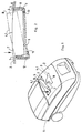
- Fig. 1 einen Bodenstaubsauger mit in die Kontur eines Deckels flächenbündig und mit sehr geringer umlaufender Spaltbreite eingesetzten Zubehörteilen und
- Fig. 2 einen Querschnitt durch eine ein Zubehörteil aufnehmende Vertiefung.
- Fig. 1 is a vacuum cleaner with flush in the contour of a lid and with very small circumferential gap accessories used and
- Fig. 2 shows a cross section through a recess receiving an accessory.
Ein Gerätegehäuse 1 eines Staubsaugers, der vorliegend als Bodenstaubsauger ausgebildet ist, weist einen gewölbten Deckel 2 auf, welcher einen im Gerätegehäuse 1 vorgesehenen Staubbeutelaufnahmeraum verschließt. In den Deckel 2 sind unterschiedlich konfigurierte Vertiefungen 3 für unterschieldich gestaltete Zubehörteile, insbesondere für Saugmundstücke 4 eingeformt. Diese Saugmundstücke 4, insbesondere eine langgestreckte Fugendüse 4 und eine T-förmige Polsterdüse sind in diese Vertiefungen 3 soweit eingesenkt, daß sie mit der Kontur des Deckels 2 abschließen. Dabei sind diese Zubehörteile jeweils mit einer der gekrümmten Öffnungsebene und Öffnungskontur der Vertiefung 3 angepaßten geschlossenen Oberseite 4.1 ausgestattet, die in der Aufbewahrungsstellung des betreffenden Zubehörteils 4 oberflächenbündig in die betreffende Gerätewand, also in die Kontur des Deckels 2 eingefügt ist, wie es bei der T-förmigen Polsterdüse dargestellt ist. Die nach oben weisende Oberseite 4.1 ist somit der einzige Teil des jeweiligen Zubehörteils, das in der Aufbewahrungsstellung nach außen weist. Der nach außen in Erscheinung tretende Spalt 5 zwischen dem umlaufenden Öffnungsrand 6 der jeweiligen Vertiefung 3 und dem angepaßten Zubehörteil 4 ist sehr eng bemessen und läßt keinen praktikablen Zugriff zum betreffenden Zubehörteil 4 zu.A device housing 1 of a vacuum cleaner, which in the present case is designed as a floor vacuum cleaner, has a curved cover 2, which closes a dust bag receiving space provided in the
Um das Zubehörteil 4 dennoch aus der Vertiefung 3 entnehmen zu können, ist es wenigstens an einem von außen zugegänglichen Endabschnitt 7 aus der Aufbewahrungsstellung in eine an der Fugendüse 4 dargestellte Zugriffstellung kippbar in der Vertiefung 3 gelagert. In der Zugriffstellung ist durch manuellen Druck auf den betreffenden Endabschnitt 7 derselbe in die Vertiefung 3 absenkbar, wobei sich das betreffende Zubehörteil mit seinem gegenüberliegenden Endabschnitt 8 aus der Ebene der Deckelwand 2 nach außen in die für den Zugriff geeignete Zugriffstellung erhebt.In order to be able to remove the accessory part 4 from the
Um diese Kippbewegung zu ermöglichen, ist vorliegend das jeweilige Zubehörteil 4 in seiner Aufbewahrungsstellung auf Stützen 9 bzw. 10 aufgelagert, wie es in Fig. 2 das in vollen Linien dargestellte Zubehörteil 4 zeigt. Die Stützen 9, 10 bestimmen somit die Eindrücktiefe des betreffenden Zubehörteils 4 und sind so angeordnet, daß der angestrebte konturengleiche Abschluß zwischen Deckelwand 2 und Oberseite 4.1 gegeben ist. Zumindest im Bereich des Endabschnitts 7 befindet sich zwischen dem Zubehörteil und einem darunter angeordneten Stützanschlag 11, der wie der Stützanschlag 10 durch den Boden der Vertiefung gebildet sein kann, ein freier Raum 12, in welchen das Zubehörteil 4 durch Druck auf den dadurch freiliegenden Endabschnitt 7 unter Kippen des gesamten Zubehörteils 4 um die benachbarte, als Kipplinie ausgebildete Stütze 9 mit dem freien Endabschnitt 7 einschwenken kann.In order to enable this tilting movement, in the present case the respective accessory 4 is supported in its storage position on
Dem jeweils abkippbaren Endabschnitt 7 eines Zubehörteils 4 kann eine Markierung zugeordnet werden, durch die erkennbar ist, auf welchen Endabschnitt bei in Aufbewahrungsstellung befindlichem Saugmundstück 4 zu drücken ist, um dieses Zubehörteil in seine Zugriffstellung auszuschwenken. Dabei können einem Zubehörteil auch mehrere Kippvorrichtung zugeordnet sein, beispielsweise der Fugendüse an beiden Endabschnitten oder der T-förmigen Polsterdüse an allen drei T-Enden oder auch an dem dem mit 7 bezeichneten Endabschnitt gegenüberliegenden Längsseitenrand dieser Polsterdüse. Auch können entsprechende Vertiefungen beispielsweise in den schmalen Längsseitenwändes des Gehäuses vorgesehen sein, um Verlängerungsrohre in gleicher Weise zu haltern, die ebenfalls mit einer der angrenzenden Gehäusekontur angepaßten Seitenflächengestaltung entsprechend der Oberseite 4.1 an den Saugdüsen 4 ausgebildet sein kann. Die Markierungen zur Bezeichnung des abkippbaren Endabschnitts 7 können an diesem Endabschnitt selbst oder am benachbarten Teil der Gerätewand oder an beiden Teilen vorgesehen sein.A mark can be assigned to the
Um die Zubehörteile sicher in der betreffenden Vertiefung 3 halten zu können, sind diese Zubehörteile vorzugsweise klemmschlüssig in der entsprechenden Vertiefung 3 gehalten. Dabei ist es zweckmäßig, den Klemmschluß im Bereich der durch die Stütze 9 vorgegebenen Klemmlinie vorzusehen, damit zum Verschwenken des betreffenden Saugmundstücks keine allzu großen Kräfte erforderlich sind. Der Klemmschluß soll jedoch so fest sein, daß sich die Zubehörteile nicht durch die im Betrieb auftretenden Kräfte selbsttätig aus der zugehörigen Vertiefung 3 lösen oder ausschwenken.In order to be able to hold the accessories securely in the
Für die Halterung der Zubehörteile sind somit keine Zusatzteile erforderlich. Dabei sind die Zubehörteile optisch sichtbar und trotzdem ästhetisch in die Form des Gerätegehäuses oberflächenbündig eingebettet. Durch die Schwenkbarkeit ergibt sich ein optimales Handling, da kein Deckel für den Zugriff zu den Zubehörteilen geöffnet oder geschlossen werden muß. Zudem stellt die besondere Gestaltung der Oberseite der Zubehörteile zugleich einen an die jeweilige Vertiefung angepaßten, integrierten Deckelabschluß dar, der die Funktionsteile der Zubehörteile abdeckt. Es wird zudem eine Zerklüftung der Oberfläche vermieden, die vielmehr durch die besondere Ausgestaltung der Oberseite der Zubehörteile in ihrer Kontur optisch erhalten bleibt. Die Funktionselemente des Zubehörs treten zudem in der Aufbewahrungsstellung nach außen nicht in Erscheinung. Im übrigen können Stützen zur lagegerechten Abstützung des Zubehörteils 4 an dessen Oberseite 8 seitlich angeformt sein, die auf angepaßten Stufenabsätzen am Öffnungsrand 6 der Vertiefung 3 in der Aufbewahrungsstellung aufliegen. Es ist dann der aus schwenkbare Zubehörteil von der Kipplinie aus mit entsprechenden Stützleisten versehen, so daß dieser Abschnitt nach Art einer Falzauflage praktisch spaltfrei ausgebildet werden kann.No additional parts are therefore required to hold the accessories. The accessories are visually visible and yet aesthetically embedded in the shape of the device housing flush with the surface. The swiveling results in optimal handling, since no lid has to be opened or closed to access the accessories. In addition, the special design of the top of the accessories also represents an integrated lid cover which is adapted to the respective recess and which covers the functional parts of the accessories. A fissuring of the surface is also avoided, the contour of which is rather retained visually by the special design of the top of the accessories. In addition, the functional elements of the accessories do not appear in the storage position. Moreover, supports for supporting the accessory 4 in the correct position can be formed laterally on its
Claims (9)
Applications Claiming Priority (2)
| Application Number | Priority Date | Filing Date | Title |
|---|---|---|---|
| DE4414406 | 1994-04-26 | ||
| DE19944414406 DE4414406C2 (en) | 1994-04-26 | 1994-04-26 | Vacuum cleaner with accessory |
Publications (2)
| Publication Number | Publication Date |
|---|---|
| EP0679361A2 true EP0679361A2 (en) | 1995-11-02 |
| EP0679361A3 EP0679361A3 (en) | 1996-05-08 |
Family
ID=6516384
Family Applications (1)
| Application Number | Title | Priority Date | Filing Date |
|---|---|---|---|
| EP95105111A Withdrawn EP0679361A3 (en) | 1994-04-26 | 1995-04-05 | Vacuum cleaner with accessory. |
Country Status (2)
| Country | Link |
|---|---|
| EP (1) | EP0679361A3 (en) |
| DE (1) | DE4414406C2 (en) |
Cited By (2)
| Publication number | Priority date | Publication date | Assignee | Title |
|---|---|---|---|---|
| EP0898922A1 (en) * | 1997-08-30 | 1999-03-03 | AEG Hausgeräte GmbH | Vacuum cleaner provided with a structure for storing accessories |
| EP1568303A1 (en) * | 2004-02-25 | 2005-08-31 | BSH Bosch und Siemens Hausgeräte GmbH | Vacuum cleaner with suction nozzle assembly |
Families Citing this family (2)
| Publication number | Priority date | Publication date | Assignee | Title |
|---|---|---|---|---|
| DE19962008A1 (en) * | 1999-12-22 | 2001-07-12 | Aeg Hausgeraete Gmbh | Vacuum cleaner with accessory compartment |
| US6374452B1 (en) | 2000-05-08 | 2002-04-23 | The Hoover Company | Tool storage door for a floor care appliance |
Citations (4)
| Publication number | Priority date | Publication date | Assignee | Title |
|---|---|---|---|---|
| US3778863A (en) * | 1972-08-02 | 1973-12-18 | Whirlpool Co | Vacuum cleaner implement tray |
| US4761850A (en) * | 1987-11-16 | 1988-08-09 | The Regina Co., Inc. | Vacuum cleaner having an integral tool holder |
| US5233722A (en) * | 1991-12-09 | 1993-08-10 | The Hoover Company | Cleaner upper portion with tool storage and door |
| US5247719A (en) * | 1990-12-24 | 1993-09-28 | The Hoover Company | Vacuum cleaner tool storage |
Family Cites Families (3)
| Publication number | Priority date | Publication date | Assignee | Title |
|---|---|---|---|---|
| DE1628702B2 (en) * | 1966-10-08 | 1977-01-27 | Licentia Patent-Verwaltungs-Gmbh, 6000 Frankfurt | SQUARE-SHAPED VACUUM HOUSING |
| DE1628685B1 (en) * | 1966-10-08 | 1971-01-07 | Licentia Gmbh | Cuboid vacuum cleaner housing |
| US4554700A (en) * | 1984-08-16 | 1985-11-26 | Whirlpool Corporation | Invisible hinge means for lid and hood of a canister vacuum cleaner |
-
1994
- 1994-04-26 DE DE19944414406 patent/DE4414406C2/en not_active Expired - Fee Related
-
1995
- 1995-04-05 EP EP95105111A patent/EP0679361A3/en not_active Withdrawn
Patent Citations (4)
| Publication number | Priority date | Publication date | Assignee | Title |
|---|---|---|---|---|
| US3778863A (en) * | 1972-08-02 | 1973-12-18 | Whirlpool Co | Vacuum cleaner implement tray |
| US4761850A (en) * | 1987-11-16 | 1988-08-09 | The Regina Co., Inc. | Vacuum cleaner having an integral tool holder |
| US5247719A (en) * | 1990-12-24 | 1993-09-28 | The Hoover Company | Vacuum cleaner tool storage |
| US5233722A (en) * | 1991-12-09 | 1993-08-10 | The Hoover Company | Cleaner upper portion with tool storage and door |
Cited By (2)
| Publication number | Priority date | Publication date | Assignee | Title |
|---|---|---|---|---|
| EP0898922A1 (en) * | 1997-08-30 | 1999-03-03 | AEG Hausgeräte GmbH | Vacuum cleaner provided with a structure for storing accessories |
| EP1568303A1 (en) * | 2004-02-25 | 2005-08-31 | BSH Bosch und Siemens Hausgeräte GmbH | Vacuum cleaner with suction nozzle assembly |
Also Published As
| Publication number | Publication date |
|---|---|
| DE4414406A1 (en) | 1995-11-02 |
| DE4414406C2 (en) | 1999-12-23 |
| EP0679361A3 (en) | 1996-05-08 |
Similar Documents
| Publication | Publication Date | Title |
|---|---|---|
| DE19948347A1 (en) | Vehicle boot construction has storage box in spare tyre socket and removable by push-fit articulated points with insert part at front end of cover which forms part of luggage boot space | |
| EP0476343A2 (en) | Box for screwdriver bits | |
| DE2924979C2 (en) | Storage for motor vehicles | |
| DE4414406C2 (en) | Vacuum cleaner with accessory | |
| EP0641726A1 (en) | Device for keeping and dispensing of hot and cold beverages | |
| EP0300322B1 (en) | Truck cabin with stowage compartment behind the driver's seat | |
| DE1194734B (en) | Dry shaver with a swivel mounted razor head | |
| DE19644542C2 (en) | Device for completely emptying bottles | |
| EP0624530B1 (en) | Container gripping device of a refuse collection vehicle for emptying refuse containers | |
| DE3515527C2 (en) | ||
| DE3844317C2 (en) | ||
| DE3440910C2 (en) | ||
| DE1680081C3 (en) | Intermediate cushions for the front seats of motor vehicles | |
| DE2939353C2 (en) | ||
| DE3625166C1 (en) | Cover device for the water container of an oral irrigator | |
| EP0118722B1 (en) | Tiltable ashtray, particularly for motor vehicles | |
| DE2532899A1 (en) | Vacuum cleaner with easily removable dust bag - has prongs in hinged lid which grip dust bags as lid swings open | |
| DE3541982A1 (en) | DEVICE FOR CARRYING DEVICES ON A WORKTOP | |
| DE7503716U (en) | Garbage bag container with a container jacket that is round or polygonal in cross section | |
| DE3245971C1 (en) | Integrated plug-in foot system | |
| DE19845255C2 (en) | Container for holding a brush | |
| DE3020571A1 (en) | Cylinder vacuum cleaner with removable dust lid - has recessed handle trough for easy carrying without unnecessary protrusions | |
| DE8204950U1 (en) | BOXED SMALL FURNITURE | |
| DE4314465A1 (en) | Coating set comprising a paint container and a paint roller set | |
| EP0650913B1 (en) | Dispenser for at least two rolls of foil |
Legal Events
| Date | Code | Title | Description |
|---|---|---|---|
| PUAI | Public reference made under article 153(3) epc to a published international application that has entered the european phase |
Free format text: ORIGINAL CODE: 0009012 |
|
| AK | Designated contracting states |
Kind code of ref document: A2 Designated state(s): DE GB IT SE |
|
| PUAL | Search report despatched |
Free format text: ORIGINAL CODE: 0009013 |
|
| AK | Designated contracting states |
Kind code of ref document: A3 Designated state(s): DE GB IT SE |
|
| STAA | Information on the status of an ep patent application or granted ep patent |
Free format text: STATUS: THE APPLICATION IS DEEMED TO BE WITHDRAWN |
|
| 18D | Application deemed to be withdrawn |
Effective date: 19961109 |