EP0678722A2 - Verfahren zur Herstellung eines rekuperativen Spiralwärmetauschers - Google Patents
Verfahren zur Herstellung eines rekuperativen Spiralwärmetauschers Download PDFInfo
- Publication number
- EP0678722A2 EP0678722A2 EP95105922A EP95105922A EP0678722A2 EP 0678722 A2 EP0678722 A2 EP 0678722A2 EP 95105922 A EP95105922 A EP 95105922A EP 95105922 A EP95105922 A EP 95105922A EP 0678722 A2 EP0678722 A2 EP 0678722A2
- Authority
- EP
- European Patent Office
- Prior art keywords
- spiral
- plate element
- partition walls
- partitions
- guide
- Prior art date
- Legal status (The legal status is an assumption and is not a legal conclusion. Google has not performed a legal analysis and makes no representation as to the accuracy of the status listed.)
- Granted
Links
Images

Classifications
-
- F—MECHANICAL ENGINEERING; LIGHTING; HEATING; WEAPONS; BLASTING
- F28—HEAT EXCHANGE IN GENERAL
- F28D—HEAT-EXCHANGE APPARATUS, NOT PROVIDED FOR IN ANOTHER SUBCLASS, IN WHICH THE HEAT-EXCHANGE MEDIA DO NOT COME INTO DIRECT CONTACT
- F28D9/00—Heat-exchange apparatus having stationary plate-like or laminated conduit assemblies for both heat-exchange media, the media being in contact with different sides of a conduit wall
- F28D9/04—Heat-exchange apparatus having stationary plate-like or laminated conduit assemblies for both heat-exchange media, the media being in contact with different sides of a conduit wall the conduits being formed by spirally-wound plates or laminae
Definitions
- the invention relates to a process for the production of a recuperative spiral heat exchanger with spiral-shaped partition walls that are bent upright from a band and stand between the fluid media streams, of which two mutually adjacent partition walls each include one of the two media streams in a guide channel, the Spiral heat exchanger has two multi-course guide channel spirals arranged one behind the other in a closed housing with opposite directions of rotation.
- a spiral heat exchanger of this type is known from European patent 0 192 212. In the manufacture of this spiral heat exchanger, it has been shown that it takes a certain amount of effort to make the spirals uniform, i. H. to produce equally proportioned flow channels for both media flows. The production of the spiral heat exchanger is therefore relatively complex and time-consuming.
- the invention has for its object to provide a method of the type mentioned, with which the manufacture of the spiral heat exchanger is simplified and accelerated.
- the partitions are introduced into at least one spiral guide gauge, and then the freely projecting longitudinal edges of one side of the partitions against all of them Guide element covering plate element, which is coated with a connecting means, be brought into contact with the spiral guide gauge after the connecting means has been tied off, and then the plate element with the dividing walls with a second plate element coated with a connecting means with the free dividing wall - Edges are brought into line for setting.
- the method according to the invention offers the advantage that the partitions run evenly when inserted into the spiral guide gauge and the guide channel spirals are thus formed precisely and true to size.
- the flow channels for both media flows are proportioned equally, since all partitions are aligned as with a template and are brought into vertical contact with the plate elements.
- Another advantage of the method is that the partition walls are connected at their longitudinal edges with the aid of a connecting means to a plate element covering the guide channels. After the connecting means has first set on one side of the partition walls, the spiral guide gauge can be dispensed with and is therefore pulled off over the still free longitudinal edges of the partition walls before these longitudinal edges of the partition walls are brought into contact with the second plate element.
- the flow channels are sealed airtight with the two plate elements. The production of the spiral heat exchanger is thus qualitatively improved on the one hand and simplified on the other hand.
- the method is characterized in that the partitions are inserted through the spiral guide. This has the advantage that the partitions can be inserted manually into the guide gauge in the simplest way.
- the method is characterized in that the partitions are drawn into the spiral guide.
- the insertion of the partition walls can advantageously be automated and carried out mechanically.
- PET film is resistant to almost all chemicals and is particularly suitable for use as a partition material because it is resistant up to a maximum continuous temperature of 250 ° C.
- a trough-shaped housing part of the spiral heat exchanger is used as the plate element.
- a hot-melt adhesive is used as the connecting means for the coating of the plate element, which can be liquefied with the introduction of heat to initiate the bonding process.
- the connecting means for the coating of the plate element which can be liquefied with the introduction of heat to initiate the bonding process.
- the partition walls which have their longitudinal edges in contact with the plate element, are completely immersed in the liquefied hotmelt adhesive by the application of heat.
- the point in time at which the setting process begins can be advantageous Interruption of the heat supply can be selected.
- the hot melt adhesive hardens completely and a firm and airtight connection is created between the partition walls and the plate element.
- the partitions can then bear against the second plate element in such a way that the first plate element is rotated with the partition walls and then aligned and fastened with the free edges to the second plate element coated with hot-melt adhesive.
- the spiral heat exchanger produced according to the invention has two multi-course spirals arranged one behind the other with opposite directions of rotation.
- the partition walls 2 connected to a plate element 1 and separating the media flows are formed from a tape made of polyethylene terephtelate (PET) film.
- PET polyethylene terephtelate
- the media flows are fed through four inflow openings 3-3 ''',4-4'''.
- Flow channels 5 are formed by two mutually adjacent partition walls 2, via which the supplied media are guided to the outlet openings 6, 6 '.
- the inflow openings 3-3 '',4-4''' and outlet openings 6, 6 ' are introduced into the plate element 1.
- the procedure for producing this spiral heat exchanger is as follows. To form the spiral arrangement of the partition walls 2, the PET film strip is inserted into a spiral-shaped guide guide 7, as can be seen in FIG. 2. All partitions 2 can be formed from one and the same film strip, so that both multi-start spirals can be produced with only one connecting seam between the beginning and end of the film. The longitudinal edges of the lower side of the partition walls 2 protrude freely from the guide gauge 7.
- the partition walls 2 Inserting into the guide gauge 7 in a spiral shape, the partition walls 2 are placed on the plate element 1 with their freely projecting lower longitudinal edges.
- the plate element 1 covering all the guide channels 5 is already a trough-shaped housing part of the spiral heat exchanger to be produced.
- the plate element 1 is coated with a hot melt adhesive 8 which, after the partition walls 2 have been aligned, is melted on the solid hot melt adhesive 8 by heating the plate element 1.
- the partitions 2 are immersed with their lower longitudinal edges, as can be seen in FIG. 2, in the hot melt adhesive 8.
- the firm connection of the partitions 2 with the plate element 1 is achieved in that the hot melt adhesive 8 hardens by interrupting the heat supply. After the hot melt adhesive 8 has completely hardened, the guide jig 7 can be completely removed from the partitions 2.
- the upper longitudinal edges of the partitions are transferred to a second, also provided with hot melt adhesive 8 plate element 1.
- the hot melt adhesive 8 is liquefied and the partition walls 2 are immersed in the hot melt adhesive 8. After the supply of heat is interrupted, the hot melt adhesive 8 hardens.
Landscapes
- Engineering & Computer Science (AREA)
- Physics & Mathematics (AREA)
- Thermal Sciences (AREA)
- Mechanical Engineering (AREA)
- General Engineering & Computer Science (AREA)
- Heat-Exchange Devices With Radiators And Conduit Assemblies (AREA)
- Screw Conveyors (AREA)
- Coating Apparatus (AREA)
Abstract
Description
- Die Erfindung betrifft ein Verfahren zur Herstellung eines rekuperativen Spiralwärmetauschers mit in Spiralform verlaufenden, aus hochkant nebeneinander stehenden aus einem Band gebogenen Trennwänden zwischen den fluiden Medienströmen, von denen jeweils zwei zueinander benachbarte Trennwände in einem Führungskanal jeweils einen der beiden Medienströme zwischen sich einschließen, wobei der Spiralwärmetauscher zwei in einem geschlossenen Gehäuse hintereinander angeordnete mehrgängige Führungskanal-Spiralen mit einander entgegengesetztem Drehsinn aufweist.
- Ein Spiralwärmetauscher dieser Art ist aus dem europäischen Patent 0 192 212 bekannt. Bei der Herstellung dieses Spiralwärmetauschers hat sich gezeigt, daß es einen bestimmten Aufwand erfordert, die Spiralen gleichmäßig auszubilden, d. h. gleich proportionierte Strömungskanäle für beide Medienströme herzustellen. Die Fertigung des Spiralwärmetauschers ist dadurch relativ aufwendig und zeitintensiv.
- Der Erfindung liegt die Aufgabe zugrunde, ein Verfahren der Eingangs genannten Gattung aufzuzeigen, mit dem die Herstellung des Spiralwärmetauschers vereinfacht und beschleunigt wird.
- Diese Aufgabe ist erfindungsgemäß dadurch gelöst worden, daß die Trennwände in mindestens eine Spiral-Führungslehre eingeführt werden, daß danach die frei vorstehenden Längsränder der einen Seite der Trennwände gegen ein sämtliche Führungskanäle abdeckendes Plattenelement, das mit einem Verbindungsmittel beschichtet ist, in Anlage gebracht werden, daß nach Abbinden des Verbindungsmittels die Spiral-Führungslehre von den Trennwänden abgezogen wird und daß anschließend das Plattenelement mit den Trennwänden mit einem zweiten mit einem Verbindungsmittel beschichteten Plattenelement mit den freien Trennwand-Rändern zum Abbinden in Anlage gebracht wird.
- Das erfindungsgemäße Verfahren bietet einmal den Vorteil, daß die Trennwände durch das Einführen in die Spiral-Führungslehre gleichmäßig verlaufen und somit die Ausbildung der Führungskanal-Spiralen genau und maßhaltig erfolgt. Die Strömungskanäle für beide Medienströme sind gleich proportioniert, da alle Trennwände wie mit einer Schablone ausgerichtet sind und lotrecht mit den Plattenelementen in Anlage gebracht werden. Ein weiterer Vorteil des Verfahrens besteht darin, daß die Trennwände an ihren Längsrändern mit Hilfe eines Verbindungsmittels mit einem die Führungskanäle abdeckenden Plattenelement verbunden werden. Nach dem Abbinden des Verbindungsmittels zunächst auf der einen Seite der Trennwände ist die Spiral-Führungslehre entbehrlich und wird diese deshalb über die noch freien Längsränder der Trennwände abgezogen, bevor auch diese Längsränder der Trennwände mit dem zweiten Plattenelement in Anlage gebracht werden. Durch den Einsatz eines Verbindungsmittels werden die Strömungskanäle mit den beiden Plattenelementen luftdicht abgeschlossen. Die Herstellung des Spiralwärmetauschers wird somit einerseits qualitativ verbessert und andererseits vereinfacht.
- Nach einer ersten Weiterbildung ist das Verfahren dadurch gekennzeichnet, daß die Trennwände durch die Spiral-Führungslehre gesteckt werden. Das hat den Vorteil, daß die Trennwände auf einfachste Weise manuell in die Führungslehre eingeführt werden können.
- Nach einer zweiten Weiterbildung ist das Verfahren dadurch gekennzeichnet, daß die Trennwände in die Spiral-Führungslehre eingezogen werden. Vorteilhaft kann auf diese Weise das Einführen der Trennwände automatisiert werden und maschinell durchgeführt werden.
- Eine andere Weiterbildung des Verfahrens sieht vor, daß als Material für die Trennwände ein Band aus Polyethylenterephtelat (PET)-Folie verwendet wird. PET-Folie ist beständig gegenüber fast allen Chemikalien und vorteilhaft für die Verwendung als Trennwandmaterial geeignet, da es bis zu einer maximalen Dauertemperatur von 250°C beständig ist.
- Nach einer anderen Weiterbildung des Verfahrens ist vorgesehen, daß als Plattenelement ein wannenförmiges Gehäuseteil des Spiralwärmetauschers verwendet wird. Das hat den Vorteil, daß die Trennwände bereits mit einem Gehäuseteil des Spiralwärmetauschers, z.B. mit einer Gehäusehälfte, verbunden werden. Mit einer zweiten Gehäusehälfte kann analog verfahren werden, so daß allein mit diesen beiden Verfahrensschritten der Spiralwärmetauscher nahezu komplettiert werden kann.
- Zur weiteren Ausbildung des erfindungsgemäßen Verfahrens ist schließlich vorgesehen, daß als Verbindungsmittel für die Beschichtung des Plattenelementes ein Schmelzkleber verwendet wird, der zur Einleitung des Klebevorganges unter Zufuhr von Wärme verflüssigbar ist. Auf dem noch festen Schmelzkleber ist es möglich, die Trennwände mit dem Vorteil so auf dem Plattenelement auszurichten, daß alle Führungskanäle durch das Plattenelement abgedeckt werden. Die mit ihren Längsrändern mit dem Plattenelement in Anlage gebrachten Trennwände tauchen durch Wärmezufuhr in den verflüssigten Schmelzkleber vollständig ein. Vorteilhaft kann bei einem Schmelzkleber der Zeitpunkt des Beginns des Abbindevorganges durch die Unterbrechung der Wärmezufuhr gewählt werden. Der Schmelzkleber härtet vollständig aus und eine feste und luftdichte Verbindung zwischen den Trennwänden und dem Plattenelement wird hergestellt. Die Anlage der Trennwände an das zweite Plattenelement kann dann in der Weise erfolgen, daß das erste Plattenelement mit den Trennwänden gedreht und anschließend mit den freien Rändern auf das mit Schmelzkleber beschichtete zweite Plattenelement ausgerichtet und befestigt wird.
- Ein Ausführungsbeispiel des Verfahrens, aus dem sich weitere erfinderische Merkmale ergeben, ist in der Zeichnung dargestellt.
- Es zeigen:
- Fig. 1
- eine schematische Schnittansicht eines Spiralwärmetauschers, der nach dem erfindungsgemäßen Verfahren gefertigt ist, und
- Fig. 2
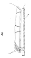
- eine teilweise geschnittene Ansicht eines Bereiches einer Führungslehre für die Durchführung des Verfahrens.
- Wie aus der Fig. 1 ersichtlich, weist der erfindungsgemäß hergestellte Spiralwärmetauscher zwei hintereinander angeordnete mehrgängige Spiralen mit einander entgegengesetztem Drehsinn auf. Die mit einem Plattenelement 1 verbundenen, die Medienströme trennenden Trennwände 2 sind aus einem Band aus Polyethylenterephtelat (PET)-Folie gebildet. Die Medienströme werden über jeweils vier Zuströmöffnungen 3-3''', 4-4''' zugeführt. Durch jeweils zwei zueinander benachbarte Trennwände 2 sind Strömungskanäle 5 ausgebildet, über welche die zugeführten Medien zu den Austrittsöffnungen 6, 6' geleitet werden. Die Zuströmöffnungen 3-3''', 4-4''' und Austrittsöffnungen 6, 6' sind in das Plattenelement 1 eingebracht.
- Beide Medien werden im Gegenstrom geführt.
- Bei der Herstellung dieses Spiralwärmetauschers wird folgendermaßen verfahren. Zur Ausbildung der spiralförmigen Anordnung der Trennwände 2 wird das PET-Folienband in eine spiralförmig geschlitzte Führungslehre 7 gesteckt, wie aus Fig. 2 ersichtlich. Sämtliche Trennwände 2 können aus ein und demselben Folienband gebildet werden, so daß beide mehrgängige Spiralen fertigungsgünstig mit nur einer Verbindungsnaht zwischen Folienanfangs- und Folienendkante ausgebildet werden können. Die Längsränder der unteren Seite der Trennwände 2 stehen aus der Führungslehre 7 frei hervor.
- In der Führungslehre 7 in Spiralform steckend werden die Trennwände 2 mit ihren frei hervorstehenden unteren Längsrändern auf das Plattenelement 1 gestellt. Das sämtliche Führungskanäle 5 abdeckende Plattenelement 1 ist bereits ein wannenförmiges Gehäuseteil des herzustellenden Spiralwärmetauschers.
- Das Plattenelement 1 ist mit einem Schmelzkleber 8 beschichtet, der nach Ausrichtung der Trennwände 2 auf dem festen Schmelzkleber 8 durch Beheizen des Plattenelementes 1 geschmolzen wird. Die Trennwände 2 tauchen dabei mit ihren unteren Längsrändern wie aus der Fig. 2 ersichtlich in den Schmelzkleber 8 ein. Die feste Verbindung der Trennwände 2 mit dem Plattenelement 1 wird dadurch erreicht, daß der Schmelzkleber 8 aushärtet, indem die Wärmezufuhr unterbrochen wird. Nach dem vollständigen Aushärten des Schmelzklebers 8 kann die Führungslehre 7 von den Trennwänden 2 ganz abgezogen werden.
- In erneuter Durchführung des Verfahrens werden nach Drehung des Plattenelementes 1 mit den daran befestigten Trennwänden 2 die oberen Längsränder der Trennwände auf ein zweites, ebenfalls mit Schmelzkleber 8 beschichtetes Plattenelement 1 gestellt. Durch Zufuhr von Wärme an das zweite Plattenelement 1, das auch ein Gehäuseteil des herzustellenden Spiralwärmetauschers ist, wird der Schmelzkleber 8 verflüssigt und die Trennwände 2 tauchen in den Schmelzkleber 8 ein. Nachdem die Zufuhr von Wärme unterbrochen ist, härtet der Schmelzkleber 8 aus.
- Im Ergebnis des Verfahrens sind sämtliche oberen und unteren Längsränder der Trennwände 2 vollständig durch die als Gehäuseteile ausgebildeten oberen und unteren Plattenelemente 1 abgedeckt. Durch die ausgehärtete, luftdichte Klebeverbindung sind beide hintereinander angeordnete mehrgängige Spiralen in einem geschlossenen, aus den Gehäuseteilen zusammengesetzten, Gehäuse angeordnet.
Claims (6)
- Verfahren zur Herstellung eines rekuperativen Spiralwärmetauschers mit in Spiralform verlaufenden, aus hochkant nebeneinander stehenden aus einem Band gebogenen Trennwänden zwischen den fluiden Medienströmen, von denen jeweils zwei zueinander benachbarte Trennwände in einem Führungskanal jeweils einen der beiden Medienströme zwischen sich einschließen, wobei der Spiralwärmetauscher zwei in einem geschlossenen Gehäuse hintereinander angeordnete mehrgängige Führungskanal-Spiralen mit einander entgegengesetztem Drehsinn aufweist, dadurch gekennzeichnet, daß die Trennwände (2) in mindestens eine Spiral-Führungslehre (7) eingeführt werden, daß danach die frei vorstehenden Längsränder der einen Seite der Trennwände (2) gegen ein sämtliche Führungskanäle (5) abdeckendes Plattenelement (1), das mit einem Verbindungsmittel beschichtet ist, in Anlage gebracht werden, daß nach Abbinden des Verbindungsmittels die Spiral-Führungslehre (7) von den Trennwänden (2) abgezogen wird und daß anschließend das Plattenelement (1) mit den Trennwänden (2) mit einem zweiten mit einem Verbindungsmittel beschichteten Plattenelement (1) mit den freien Trennwand-Rändern zum Abbinden in Anlage gebracht wird.
- Verfahren nach Anspruch 1, dadurch gekennzeichnet, daß die Trennwände (2) durch die Spiral-Führungslehre (7) gesteckt werden.
- Verfahren nach Anspruch 1, dadurch gekennzeichnet, daß die Trennwände (2) in die Spiral-Führungslehre (7) eingezogen werden .
- Verfahren nach Anspruch 2 oder 3, dadurch gekennzeichnet, daß als Material für die Trennwände (2) ein Band aus Polyethylenterephtelat (PET)-Folie verwendet wird.
- Verfahren nach Anspruch 2 oder 3, dadurch gekennzeichnet, daß als Plattenelement (1) ein wannenförmiges Gehäuseteil des Spiralwärmetauschers verwendet wird.
- Verfahren nach Anspruch 2 oder 3, dadurch gekennzeichnet, daß als Verbindungsmittel für die Beschichtung des Plattenelementes (1) ein Schmelzkleber (8) verwendet wird, der zur Einleitung des Klebevorganges unter Zufuhr von Wärme verflüssigt wird.
Applications Claiming Priority (2)
| Application Number | Priority Date | Filing Date | Title |
|---|---|---|---|
| DE4413867A DE4413867A1 (de) | 1994-04-21 | 1994-04-21 | Verfahren zur Herstellung eines rekuperativen Spiralwärmetauschers |
| DE4413867 | 1994-04-21 |
Publications (3)
| Publication Number | Publication Date |
|---|---|
| EP0678722A2 true EP0678722A2 (de) | 1995-10-25 |
| EP0678722A3 EP0678722A3 (de) | 1996-04-10 |
| EP0678722B1 EP0678722B1 (de) | 1999-01-13 |
Family
ID=6516037
Family Applications (1)
| Application Number | Title | Priority Date | Filing Date |
|---|---|---|---|
| EP95105922A Expired - Lifetime EP0678722B1 (de) | 1994-04-21 | 1995-04-20 | Verfahren zur Herstellung eines rekuperativen Spiralwärmetauschers |
Country Status (3)
| Country | Link |
|---|---|
| EP (1) | EP0678722B1 (de) |
| AT (1) | ATE175771T1 (de) |
| DE (2) | DE4413867A1 (de) |
Cited By (2)
| Publication number | Priority date | Publication date | Assignee | Title |
|---|---|---|---|---|
| EP1895259A1 (de) * | 2006-08-01 | 2008-03-05 | Makatec GmbH | Folienwärmeübertrager für Fluide |
| WO2010099946A3 (de) * | 2009-03-04 | 2011-02-03 | Makatec Gmbh | Wärmetauscher zur ölkühlung |
Families Citing this family (3)
| Publication number | Priority date | Publication date | Assignee | Title |
|---|---|---|---|---|
| ATE262154T1 (de) * | 1998-10-02 | 2004-04-15 | Erling Vage | Wärmetauscher, verfahren und vorrichtung zu dessen herstellung |
| RU2358218C1 (ru) * | 2008-01-28 | 2009-06-10 | Леонид Владимирович Чумазов | Спиральный теплообменник и способ его изготовления |
| RU2397052C2 (ru) * | 2008-10-09 | 2010-08-20 | Альберт Викторович Королев | Способ изготовления деталей |
Family Cites Families (16)
| Publication number | Priority date | Publication date | Assignee | Title |
|---|---|---|---|---|
| FR442440A (fr) * | 1911-05-09 | 1912-08-31 | Hammersley Heenan | Appareil pour refroidir et chauffer de l'eau, de l'air et d'autres corps |
| US2142679A (en) * | 1935-04-09 | 1939-01-03 | Rosenblads Patenter Ab | Heat exchanger |
| DE666910C (de) * | 1937-02-25 | 1938-10-31 | Albert Benteli | Waermeaustauscher mit einer Anzahl von in Spiralform gewickelter Bleche |
| BE449424A (de) * | 1941-12-30 | |||
| DE1063355B (de) * | 1952-05-13 | 1959-08-13 | Therma Fabrik Fuer Elek Sche H | Vorrichtung zur Beheizung von Waermegefaessen, wie Kochkessel, Autoklaven, und Verfahren zur Herstellung solcher Vorrichtungen |
| DE1417079B1 (de) * | 1959-06-03 | 1970-04-02 | Jaeger Dipl Ing Joerg | Anwendung der Bauanordnung einer Fluessigkeitstrennvorrichtung auf Waermeaustauscher und Rauchgasreiniger |
| DE1245894B (de) * | 1959-11-27 | 1967-08-03 | Siemens Elektrogeraete Gmbh | Verfahren zur Herstellung von beispielsweise aus Stahlblech gefertigten Kochplatten |
| GB1398594A (en) * | 1972-03-28 | 1975-06-25 | Int Computers Ltd | Methods for the manufacture of electrical connectors |
| DE3119345A1 (de) * | 1981-05-15 | 1982-12-02 | Hoechst Ag, 6000 Frankfurt | Mehrlagenbahn, verfahren zu ihrer herstellung und ihre verwendung als waermeaustauscherelement |
| EP0077009A1 (de) * | 1981-10-14 | 1983-04-20 | Feraton Anstalt | Verfahren zur Herstellung eines Wärmetauschers |
| DE3242260A1 (de) * | 1982-11-15 | 1984-05-17 | Thermal-Werke, Wärme-, Kälte-, Klimatechnik GmbH, 6909 Walldorf | Waermetauscher |
| DE3505789A1 (de) * | 1985-02-20 | 1986-08-21 | Grote, Paul, 2901 Friedrichsfehn | Spiralwaermetauscher |
| DE3521708A1 (de) * | 1985-06-18 | 1986-12-18 | Ralf 5100 Aachen Deubgen | Schmelzklebstoffbeschichteter hitzedraht |
| DE3605003A1 (de) * | 1986-02-18 | 1987-08-20 | Herberts Gmbh | Waermehaertbare klebfolie, verfahren zu ihrer herstellung und ihre verwendung |
| JPH0624793B2 (ja) * | 1987-08-27 | 1994-04-06 | 伸和工業株式会社 | 金属パイルの植毛方法 |
| DE4221528A1 (de) * | 1992-07-01 | 1994-01-05 | Hans Dr Viesmann | Nachschaltwärmetauscher für den Einbau in Heizkesselgehäuse und Verfahren zu dessen Herstellung |
-
1994
- 1994-04-21 DE DE4413867A patent/DE4413867A1/de not_active Withdrawn
-
1995
- 1995-04-20 DE DE59504776T patent/DE59504776D1/de not_active Expired - Lifetime
- 1995-04-20 EP EP95105922A patent/EP0678722B1/de not_active Expired - Lifetime
- 1995-04-20 AT AT95105922T patent/ATE175771T1/de not_active IP Right Cessation
Cited By (2)
| Publication number | Priority date | Publication date | Assignee | Title |
|---|---|---|---|---|
| EP1895259A1 (de) * | 2006-08-01 | 2008-03-05 | Makatec GmbH | Folienwärmeübertrager für Fluide |
| WO2010099946A3 (de) * | 2009-03-04 | 2011-02-03 | Makatec Gmbh | Wärmetauscher zur ölkühlung |
Also Published As
| Publication number | Publication date |
|---|---|
| ATE175771T1 (de) | 1999-01-15 |
| DE4413867A1 (de) | 1995-10-26 |
| EP0678722B1 (de) | 1999-01-13 |
| DE59504776D1 (de) | 1999-02-25 |
| EP0678722A3 (de) | 1996-04-10 |
Similar Documents
| Publication | Publication Date | Title |
|---|---|---|
| EP0655275A1 (de) | Statische Mischvorrichtung | |
| DE2338070A1 (de) | Fraktionierungsvorrichtung | |
| CH645058A5 (de) | Verfahren und vorrichtung zum spritzgiessen. | |
| DE69401610T2 (de) | Wärmetauscher | |
| EP0760253A1 (de) | Statischer Mischer für zähe Fluide | |
| DE10036133A1 (de) | Wärmetauscher und darin verwendbares Rohr, das nahe der Rohrenden größere gegenüberliegende Vorsprünge hat | |
| EP0176729A1 (de) | Wärmetauscher sowie Verfahren und Vorrichtung zur Herstellung derselben | |
| EP0387678A1 (de) | Wärmeaustauscher und Verfahren zur flüssigkeitsdichten Befestigung einer Bodenplatte an einem Wärmeaustauschernetz | |
| DE3049168A1 (de) | Waermetauscher mit flachrohren und verfahren zum herstellen desselben | |
| DE3928453A1 (de) | Waermetauscher und ein verfahren zur herstellung einer dichtung fuer einen waermetauscher | |
| DE2135813A1 (de) | Schwebstoffiltereinsatz für Atemschutzgeräte aus einer gefalteten Filterschicht | |
| DE2739998B2 (de) | Strangpreßvorrichtung zur Herstellung von geschäumtem Kunststoff | |
| EP0678722B1 (de) | Verfahren zur Herstellung eines rekuperativen Spiralwärmetauschers | |
| DE1917903C3 (de) | Verfahren zum dichten Verbinden einer gefalteten Filterpackung mit Filterrahmenteilen, und Filter, hergestellt nach dem Verfahren | |
| DE3212295A1 (de) | Verfahren zum verbinden zweier flaechen von platten | |
| DE69709388T2 (de) | Verfahren und vorrichtung zur herstellung von farbrollern | |
| DE10063211A1 (de) | Mehrkammertube | |
| DE3543930A1 (de) | Schrumpfbare kabelmuffe | |
| DE3005078C2 (de) | ||
| DE69708703T2 (de) | Verfahren und vorrichtung zur herstellung einer flexiblen schlauchkombination | |
| CH668118A5 (de) | Verfahren zur herstellung eines waermetauschers. | |
| EP0891510B1 (de) | Verfahren zum herstellen einer aus thermisch anschweissbarem material bestehenden rohrarmatur | |
| DE19646184A1 (de) | Verfahren zum Herstellen einer Chipkarte und Vorrichtung zum Durchführen des Verfahrens | |
| DE3401853A1 (de) | Waermetauscher und verfahren zu seiner herstellung | |
| DE3146168C2 (de) | Induktives Bauelement, insbesondere Spule für hohe und sehr hohe Frequenzen sowie Verfahren zur Herstellung eines solchen Bauelementes |
Legal Events
| Date | Code | Title | Description |
|---|---|---|---|
| PUAI | Public reference made under article 153(3) epc to a published international application that has entered the european phase |
Free format text: ORIGINAL CODE: 0009012 |
|
| AK | Designated contracting states |
Kind code of ref document: A2 Designated state(s): AT BE CH DE DK ES FR GB GR IE IT LI LU MC NL PT SE |
|
| PUAL | Search report despatched |
Free format text: ORIGINAL CODE: 0009013 |
|
| AK | Designated contracting states |
Kind code of ref document: A3 Designated state(s): AT BE CH DE DK ES FR GB GR IE IT LI LU MC NL PT SE |
|
| 17P | Request for examination filed |
Effective date: 19961010 |
|
| GRAG | Despatch of communication of intention to grant |
Free format text: ORIGINAL CODE: EPIDOS AGRA |
|
| 17Q | First examination report despatched |
Effective date: 19980318 |
|
| GRAG | Despatch of communication of intention to grant |
Free format text: ORIGINAL CODE: EPIDOS AGRA |
|
| GRAH | Despatch of communication of intention to grant a patent |
Free format text: ORIGINAL CODE: EPIDOS IGRA |
|
| GRAH | Despatch of communication of intention to grant a patent |
Free format text: ORIGINAL CODE: EPIDOS IGRA |
|
| GRAA | (expected) grant |
Free format text: ORIGINAL CODE: 0009210 |
|
| AK | Designated contracting states |
Kind code of ref document: B1 Designated state(s): AT BE CH DE DK ES FR GB GR IE IT LI LU MC NL PT SE |
|
| PG25 | Lapsed in a contracting state [announced via postgrant information from national office to epo] |
Ref country code: SE Free format text: THE PATENT HAS BEEN ANNULLED BY A DECISION OF A NATIONAL AUTHORITY Effective date: 19990113 Ref country code: IT Free format text: LAPSE BECAUSE OF FAILURE TO SUBMIT A TRANSLATION OF THE DESCRIPTION OR TO PAY THE FEE WITHIN THE PRESCRIBED TIME-LIMIT;WARNING: LAPSES OF ITALIAN PATENTS WITH EFFECTIVE DATE BEFORE 2007 MAY HAVE OCCURRED AT ANY TIME BEFORE 2007. THE CORRECT EFFECTIVE DATE MAY BE DIFFERENT FROM THE ONE RECORDED. Effective date: 19990113 Ref country code: GR Free format text: LAPSE BECAUSE OF NON-PAYMENT OF DUE FEES Effective date: 19990113 Ref country code: GB Free format text: LAPSE BECAUSE OF NON-PAYMENT OF DUE FEES Effective date: 19990113 Ref country code: FR Free format text: LAPSE BECAUSE OF FAILURE TO SUBMIT A TRANSLATION OF THE DESCRIPTION OR TO PAY THE FEE WITHIN THE PRESCRIBED TIME-LIMIT Effective date: 19990113 Ref country code: ES Free format text: THE PATENT HAS BEEN ANNULLED BY A DECISION OF A NATIONAL AUTHORITY Effective date: 19990113 |
|
| REF | Corresponds to: |
Ref document number: 175771 Country of ref document: AT Date of ref document: 19990115 Kind code of ref document: T |
|
| REG | Reference to a national code |
Ref country code: CH Ref legal event code: EP |
|
| REG | Reference to a national code |
Ref country code: IE Ref legal event code: FG4D Free format text: GERMAN |
|
| REF | Corresponds to: |
Ref document number: 59504776 Country of ref document: DE Date of ref document: 19990225 |
|
| PG25 | Lapsed in a contracting state [announced via postgrant information from national office to epo] |
Ref country code: PT Free format text: LAPSE BECAUSE OF FAILURE TO SUBMIT A TRANSLATION OF THE DESCRIPTION OR TO PAY THE FEE WITHIN THE PRESCRIBED TIME-LIMIT Effective date: 19990413 Ref country code: DK Free format text: LAPSE BECAUSE OF FAILURE TO SUBMIT A TRANSLATION OF THE DESCRIPTION OR TO PAY THE FEE WITHIN THE PRESCRIBED TIME-LIMIT Effective date: 19990413 |
|
| PG25 | Lapsed in a contracting state [announced via postgrant information from national office to epo] |
Ref country code: LU Free format text: LAPSE BECAUSE OF NON-PAYMENT OF DUE FEES Effective date: 19990420 |
|
| PG25 | Lapsed in a contracting state [announced via postgrant information from national office to epo] |
Ref country code: BE Free format text: LAPSE BECAUSE OF NON-PAYMENT OF DUE FEES Effective date: 19990430 |
|
| REG | Reference to a national code |
Ref country code: CH Ref legal event code: NV Representative=s name: PATENTANWAELTE SCHAAD, BALASS, MENZL & PARTNER AG |
|
| EN | Fr: translation not filed | ||
| GBV | Gb: ep patent (uk) treated as always having been void in accordance with gb section 77(7)/1977 [no translation filed] |
Effective date: 19990113 |
|
| PG25 | Lapsed in a contracting state [announced via postgrant information from national office to epo] |
Ref country code: IE Free format text: LAPSE BECAUSE OF NON-PAYMENT OF DUE FEES Effective date: 19990820 |
|
| REG | Reference to a national code |
Ref country code: IE Ref legal event code: FD4D |
|
| BERE | Be: lapsed |
Owner name: GROTE PAUL Effective date: 19990430 |
|
| PG25 | Lapsed in a contracting state [announced via postgrant information from national office to epo] |
Ref country code: MC Free format text: LAPSE BECAUSE OF NON-PAYMENT OF DUE FEES Effective date: 19991031 |
|
| PLBE | No opposition filed within time limit |
Free format text: ORIGINAL CODE: 0009261 |
|
| STAA | Information on the status of an ep patent application or granted ep patent |
Free format text: STATUS: NO OPPOSITION FILED WITHIN TIME LIMIT |
|
| 26N | No opposition filed | ||
| PGFP | Annual fee paid to national office [announced via postgrant information from national office to epo] |
Ref country code: NL Payment date: 20041022 Year of fee payment: 10 |
|
| PGFP | Annual fee paid to national office [announced via postgrant information from national office to epo] |
Ref country code: AT Payment date: 20041025 Year of fee payment: 10 |
|
| PGFP | Annual fee paid to national office [announced via postgrant information from national office to epo] |
Ref country code: CH Payment date: 20041027 Year of fee payment: 10 |
|
| PG25 | Lapsed in a contracting state [announced via postgrant information from national office to epo] |
Ref country code: AT Free format text: LAPSE BECAUSE OF NON-PAYMENT OF DUE FEES Effective date: 20050420 |
|
| PG25 | Lapsed in a contracting state [announced via postgrant information from national office to epo] |
Ref country code: LI Free format text: LAPSE BECAUSE OF NON-PAYMENT OF DUE FEES Effective date: 20050430 Ref country code: CH Free format text: LAPSE BECAUSE OF NON-PAYMENT OF DUE FEES Effective date: 20050430 |
|
| PG25 | Lapsed in a contracting state [announced via postgrant information from national office to epo] |
Ref country code: NL Free format text: LAPSE BECAUSE OF NON-PAYMENT OF DUE FEES Effective date: 20051101 |
|
| REG | Reference to a national code |
Ref country code: CH Ref legal event code: PL |
|
| NLV4 | Nl: lapsed or anulled due to non-payment of the annual fee |
Effective date: 20051101 |
|
| PGFP | Annual fee paid to national office [announced via postgrant information from national office to epo] |
Ref country code: DE Payment date: 20110519 Year of fee payment: 17 |
|
| REG | Reference to a national code |
Ref country code: DE Ref legal event code: R119 Ref document number: 59504776 Country of ref document: DE Effective date: 20121101 |
|
| PG25 | Lapsed in a contracting state [announced via postgrant information from national office to epo] |
Ref country code: DE Free format text: LAPSE BECAUSE OF NON-PAYMENT OF DUE FEES Effective date: 20121101 |