EP0678284B1 - Filtre sanguin à usage temporaire ou définitif et son dispositif d'implantation, - Google Patents
Filtre sanguin à usage temporaire ou définitif et son dispositif d'implantation, Download PDFInfo
- Publication number
- EP0678284B1 EP0678284B1 EP95400850A EP95400850A EP0678284B1 EP 0678284 B1 EP0678284 B1 EP 0678284B1 EP 95400850 A EP95400850 A EP 95400850A EP 95400850 A EP95400850 A EP 95400850A EP 0678284 B1 EP0678284 B1 EP 0678284B1
- Authority
- EP
- European Patent Office
- Prior art keywords
- blood filter
- filter
- blood
- implantation
- sheath
- Prior art date
- Legal status (The legal status is an assumption and is not a legal conclusion. Google has not performed a legal analysis and makes no representation as to the accuracy of the status listed.)
- Expired - Lifetime
Links
Images


Classifications
-
- A—HUMAN NECESSITIES
- A61—MEDICAL OR VETERINARY SCIENCE; HYGIENE
- A61F—FILTERS IMPLANTABLE INTO BLOOD VESSELS; PROSTHESES; DEVICES PROVIDING PATENCY TO, OR PREVENTING COLLAPSING OF, TUBULAR STRUCTURES OF THE BODY, e.g. STENTS; ORTHOPAEDIC, NURSING OR CONTRACEPTIVE DEVICES; FOMENTATION; TREATMENT OR PROTECTION OF EYES OR EARS; BANDAGES, DRESSINGS OR ABSORBENT PADS; FIRST-AID KITS
- A61F2/00—Filters implantable into blood vessels; Prostheses, i.e. artificial substitutes or replacements for parts of the body; Appliances for connecting them with the body; Devices providing patency to, or preventing collapsing of, tubular structures of the body, e.g. stents
- A61F2/01—Filters implantable into blood vessels
- A61F2/011—Instruments for their placement or removal
-
- A—HUMAN NECESSITIES
- A61—MEDICAL OR VETERINARY SCIENCE; HYGIENE
- A61F—FILTERS IMPLANTABLE INTO BLOOD VESSELS; PROSTHESES; DEVICES PROVIDING PATENCY TO, OR PREVENTING COLLAPSING OF, TUBULAR STRUCTURES OF THE BODY, e.g. STENTS; ORTHOPAEDIC, NURSING OR CONTRACEPTIVE DEVICES; FOMENTATION; TREATMENT OR PROTECTION OF EYES OR EARS; BANDAGES, DRESSINGS OR ABSORBENT PADS; FIRST-AID KITS
- A61F2/00—Filters implantable into blood vessels; Prostheses, i.e. artificial substitutes or replacements for parts of the body; Appliances for connecting them with the body; Devices providing patency to, or preventing collapsing of, tubular structures of the body, e.g. stents
- A61F2/01—Filters implantable into blood vessels
- A61F2/0105—Open ended, i.e. legs gathered only at one side
-
- A—HUMAN NECESSITIES
- A61—MEDICAL OR VETERINARY SCIENCE; HYGIENE
- A61F—FILTERS IMPLANTABLE INTO BLOOD VESSELS; PROSTHESES; DEVICES PROVIDING PATENCY TO, OR PREVENTING COLLAPSING OF, TUBULAR STRUCTURES OF THE BODY, e.g. STENTS; ORTHOPAEDIC, NURSING OR CONTRACEPTIVE DEVICES; FOMENTATION; TREATMENT OR PROTECTION OF EYES OR EARS; BANDAGES, DRESSINGS OR ABSORBENT PADS; FIRST-AID KITS
- A61F2/00—Filters implantable into blood vessels; Prostheses, i.e. artificial substitutes or replacements for parts of the body; Appliances for connecting them with the body; Devices providing patency to, or preventing collapsing of, tubular structures of the body, e.g. stents
- A61F2/01—Filters implantable into blood vessels
- A61F2002/016—Filters implantable into blood vessels made from wire-like elements
-
- A—HUMAN NECESSITIES
- A61—MEDICAL OR VETERINARY SCIENCE; HYGIENE
- A61F—FILTERS IMPLANTABLE INTO BLOOD VESSELS; PROSTHESES; DEVICES PROVIDING PATENCY TO, OR PREVENTING COLLAPSING OF, TUBULAR STRUCTURES OF THE BODY, e.g. STENTS; ORTHOPAEDIC, NURSING OR CONTRACEPTIVE DEVICES; FOMENTATION; TREATMENT OR PROTECTION OF EYES OR EARS; BANDAGES, DRESSINGS OR ABSORBENT PADS; FIRST-AID KITS
- A61F2230/00—Geometry of prostheses classified in groups A61F2/00 - A61F2/26 or A61F2/82 or A61F9/00 or A61F11/00 or subgroups thereof
- A61F2230/0002—Two-dimensional shapes, e.g. cross-sections
- A61F2230/0028—Shapes in the form of latin or greek characters
- A61F2230/005—Rosette-shaped, e.g. star-shaped
-
- A—HUMAN NECESSITIES
- A61—MEDICAL OR VETERINARY SCIENCE; HYGIENE
- A61F—FILTERS IMPLANTABLE INTO BLOOD VESSELS; PROSTHESES; DEVICES PROVIDING PATENCY TO, OR PREVENTING COLLAPSING OF, TUBULAR STRUCTURES OF THE BODY, e.g. STENTS; ORTHOPAEDIC, NURSING OR CONTRACEPTIVE DEVICES; FOMENTATION; TREATMENT OR PROTECTION OF EYES OR EARS; BANDAGES, DRESSINGS OR ABSORBENT PADS; FIRST-AID KITS
- A61F2230/00—Geometry of prostheses classified in groups A61F2/00 - A61F2/26 or A61F2/82 or A61F9/00 or A61F11/00 or subgroups thereof
- A61F2230/0063—Three-dimensional shapes
- A61F2230/0067—Three-dimensional shapes conical
-
- A—HUMAN NECESSITIES
- A61—MEDICAL OR VETERINARY SCIENCE; HYGIENE
- A61F—FILTERS IMPLANTABLE INTO BLOOD VESSELS; PROSTHESES; DEVICES PROVIDING PATENCY TO, OR PREVENTING COLLAPSING OF, TUBULAR STRUCTURES OF THE BODY, e.g. STENTS; ORTHOPAEDIC, NURSING OR CONTRACEPTIVE DEVICES; FOMENTATION; TREATMENT OR PROTECTION OF EYES OR EARS; BANDAGES, DRESSINGS OR ABSORBENT PADS; FIRST-AID KITS
- A61F2230/00—Geometry of prostheses classified in groups A61F2/00 - A61F2/26 or A61F2/82 or A61F9/00 or A61F11/00 or subgroups thereof
- A61F2230/0063—Three-dimensional shapes
- A61F2230/0073—Quadric-shaped
- A61F2230/0078—Quadric-shaped hyperboloidal
Definitions
- the subject of the invention is an assembly comprising a medical filter intended to be positioned in a blood vessel for trap clots that can circulate there and its device implantation.
- the practitioner usually uses the endovenous route, by either denuding vascular either by following an introductory technique called percutaneous.
- Percutaneous technique is the least aggressive because a device of the introducer type catheter can be used for the introduction of the jugular or femoral filter. After having made an incision of the skin, the filter is thus introduced into the retained vein, then guided to the inferior vena cava where it is "expelled" out of the device. It thus expands in the vein, preventing migration of clots going to the heart and pulmonary artery and avoiding embolism.
- Such filters are for example described in patents US-A-3,540,431, US-A-4,688,553 or still in FR-A-2 689 388.
- these filters Being permanently established, these filters must be attached to the vein and include often for this hooks which are anchored in the vessel wall at the time the filter is released and expands radially (often on its own, number of filters being "self-expanding").
- EP-A-0 348 295 a set filtration for temporary and / or permanent use which includes, on the one hand, a filter with flexible legs defining two head-to-tail corollas (one of filtration and the other to keep the filter in definitive implantation in the vessel) and, on the other part, a double catheter to hold the filter in temporary establishment.
- the filter is kept linked to the double catheter simply by rubbing the legs of its retaining corolla against the catheter wall external.
- the filter In final use, the filter is found completely expanded in the vessel, with its corolla for holding against the wall of the vessel to attach the filter, the double catheter normally being removed from the patient's body.
- the invention proposes a solution which allows to change the filter once installed temporary use towards final use, without requiring a long and delicate operation, without change of instrumentation, this under conditions reliability of installation and easy control of. movement of the filter in the body.
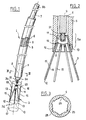
- FIG 1 we see illustrated a assembly according to the invention which comprises a device 1 implantation and use of a blood filter 3, this device 1 being known in its characteristics general (for example described in FR-A-2 657 261 or US-A-4,688,553).
- it essentially comprises a outer sheath 5 of biocompatible material, of axis general longitudinal 7, inside which can be housed the filter 3 in a radially folded state.
- an operating rod 9 made of biocompatible material, is mounted axially sliding in the sheath.
- the filter 3 which has an axis 2, a proximal end 3 p and an opposite distal end 3 d , comprises a head 11, for example in the form of a 'warhead, from which come legs 13, at least some of which extend at their free end 12, by appendages 15 for centering and holding the filter against the vessel. These appendages return back towards the head 11, so that the legs thus formed have a general hairpin shape.
- the tabs and the appendages to which they are connected may be made of simple or looped metal wire, or like thin strips, so that in a radially unstressed state the filter 3 develops, at the location of these tabs 13, in a substantially conical corolla, widening from the head 11 to the end 3 d , while the appendages 15 will extend towards the closing side of the cone, being substantially parallel to the wall of the cylinder 17 generated by a generating line parallel to the axis 7 of the cone formed by the filter and moving by describing the line 18 defining the opening perimeter of the filter.
- This filter can be used in definitive implantation, it is equipped with means of fixing or anchoring 19.
- the hooks 19 have been provided here only on appendices 15, on the side of their free end 16, so as to avoid any risk of unwanted anchoring, in a "temporary" use, as will be seen below.
- the distal end 9a (intended to be installed most deeply in the patient) of the rod 9 and the head 11 of the filter are arranged to be able to be interconnected, removable way.
- these removable connection means consist of mechanical means, for example relative screwing means.
- the end 9a of the rod has a threaded axial extension 21 suitable for engage in a thread 23 provided axially in the filter head 11.
- Figure 2 which also shows the filter 3 and device 1 used together in as part of a temporary installation of the filter, we further note the arrangement of square brackets 19 to inside the sheath 5, in relation to the partially retracted arrangement of the filter.
- the means connecting rod / filter consist of means of relative screwing
- the sheath presents, at its extreme part distal marked by zone 5a, an inner surface notched.
- a series of interior notches 25 in the form of slots substantially parallel to the axis 7 of the sheath can thus be provided so that each slot receives one of the appendages 15 in acting on it to constitute means of restraint in rotation of the filter when the practitioner is going to act on the rod 9 to unscrew it for the passage of a temporary establishment to permanent establishment.
- the radial natural elasticity towards the exterior of the appendages favoring their engagement in the notches.
- distal zone 5a of the tubular sheath may have an axial internal passage 8 of enlarged diameter compared to that 6 located further upstream, so that promote good positioning of the filter head and an opening diameter sufficient for development of this filter in the position of temporary installation as in this figure 2.
- a first variant 3 1 and a second variant 3 2 of the filter of the invention are shown. They include, like the filter 3, a substantially conical filtration part, devoid of means for anchoring to the vessel and formed by the head 11 (here provided with means of connection with the rod 9) from which the first legs 13 1 originate. a, 13 2 a substantially straight which extend to the distal end 3 d of the filter.
- filters 3 1 and 3 2 each include a series of second legs 13 1 b and 13 2 b, at least some of which are extended by appendages 15 1 and 15 2 for holding in place and centering respectively. filters 3 1 and 3 2 in the vessel. These appendages comprise means 19 for fixing the filter against the wall of the vessel, these hooks 19 being spaced from the end 3 d of the filter.
- the second legs and their appendages have a general hairpin shape and can be formed in one piece.
- the tabs 13 1b of the filter 3 1 shall be fixed at a fixing end 14 1, the filter portion (at head 11). They extend from this head to the end 3 p of the filter, so that, in their radially unstressed state, they define a second substantially conical corolla, the first filtration corolla and the second corolla being head- spade.
- each leg 13 2 b is fixed to a leg 13 2 a, in a portion or zone of this leg separated from its opposite ends (for example substantially in the middle) so that, in their state unconstrained, the legs 13 2 b extend from their fixing end 14 2 to the legs 13 2 a along a second corolla or a tubular surface flaring, of axis 2 (which surrounds the head 11).
- the opening perimeters of the first and second corollas may be substantially equal (the second corolla also filtering the blood which crosses).
- the appendages 15 1 and 15 2 extend, here substantially over their entire length, substantially parallel to the axis 2, defining a tubular surface of section substantially equal to that of the vessel for that these appendages come into contact with the vessel wall and attach the filter to it. These appendages are directed towards the end 3 d of the filter, thus the second corolla extends inside the tubular surface defined by the appendages.
- Appendages and second legs may consist of round metallic wires or flat, the second legs being for example welded on the first corolla.
- the filter 3 3 of FIG. 11 differs from that of FIG. 7 in particular in that each second tab 13 3 b and its appendage 15 3 are produced, preferably in one piece, by a flexible wire folded over itself. even in a loop (s) and the two opposite ends of which, close to one another, are fixed at the level of the head 11 (for more details on the construction of these legs 13 3 b and their appendages, we may refer to US 5,344,427).
- the legs 13 3 a they comprise a main part 131 3 of wire connected to the head and which is extended by a distal part 132 3 with a non-aggressive contour with respect to the vessel and of section greater than that of the wire to increase the bearing surface of the filter against the wall by slowing down the confinement of these distal parts by the tissues of the vessel.
- the filters 3 3 in FIG. 11 and 3 4 in FIG. 10 are distinguished respectively from the filters 3 1 and 3 2 in that the removable connection means here comprise means for clamping, or for axial locking of the rod. , which are provided on the second legs 13 3 b (filter 3 3 ) and 13 4 b (filter 3 4 ) in a zone 135 3 , 135 4 intermediate between the head 11 and the proximal end of the filter (therefore separated from the ends opposite sides of the filter). These clamping means cooperate with complementary means of the rod which comprise at least one cooperating stop.
- the appendages 15 3 are only over part of their length parallel to the axis 2.
- the rod 9 3 ends with a swollen end 9 3 a which has two stops 91 3 and 92 3 , at least some of the legs 13 3 b having locally a curved portion or slot 30 3 for housing this swollen end.
- the slots 30 3 enclose or trap the end 9 3 a of the rod, coming to bear against the stops for prevent axial displacement of the rod relative to the filter.
- the clamping means outside the sheath, are moved away from the stops because of the radial expansion of the second legs.
- the second legs 13 4 b carry flexible tongues 30 4 which project locally relative to the legs to block the end 9 3 a.
- These tongues extend over most of their length along the legs to which they are linked and deviate therefrom towards one of their ends, which is free, to come to bear, in temporary use of the filter (when the legs 13 4 b are constrained in the sheath) against a stop 91 4 of the swollen end of the rod, while a second stop 92 4 of this swollen end bears against the head 11 of the filter.
- the filter head cooperates with the tongues for blocking the rod.
- the tongues are spaced radially from the rod which is thus released.
- the rod here has a small diameter outer relative to the inner diameter of the sheath so that the second legs and their appendages are arranged between the rod and the sheath in the temporary use of the filter.
- Figure 5 shows the device in the part of a temporary filtration, the filter being so as in its position in figure 2 where the part of its corolla located outside the sheath flourishes so as to occupy most of the diameter of the vessel by playing its filtration role, facing the blood flow diagrammed by arrow 29.
- the anchoring means 19 are always housed inside the sheath, the part of the appendices 15 still located inside this sheath being here constrained along the legs, following substantially the same configuration in corolla.
- the practitioner judges that the risks of embolism have decreased enough, he can then withdraw the entire device, including the filter. For this, he just has to pull back the sheath (arrow 33), thus simultaneously removing the rod and the filter.
- the practitioner notices that a final implantation of the filter 3 is preferable, it then suffices to maintain the sheath 5 still implanted and act on the proximal end 9b of the rod 9 to unscrew it from the head of the filter, which is prevented from turning by the notches 25.
- the means 15 define a tubular surface substantially cylindrical centered in the axis 33 of the vessel 31 against which they apply, the means filtration 11, 13 extending inside this surface to retain any clots, while letting the blood circulate, the direction of circulation is always shown diagrammatically by arrow 29.
- the practitioner can of course remove the sheath and the rod 9 (separated from the filter) by their location, the filter being left permanently.
- the separable connection filter / rod could be secured by at least one wire 100, or equivalent means, fixed at the same time to the rod 9, along which it extends, and to the filter (at its head 11) to keep them together in one use temporary filter.
- This wire for example steel stainless, is covered with an insulating film (in particular in Teflon) except in its portion 102 ensuring the connection between the rod and the filter.
- this thread can be locally destroyed or cut at the junction 102, the practitioner acting at a distance. For that, we connects the proximal end of the wire to a source of current disposed outside the patient's body.
- the filter it could be the FR 92 09 845 demand filter (leg filter triangulated) or that of application FR 92 15 774 with zigzag shaped appendages.
Description
- trois tubes coaxiaux (gaine et double-cathéter) sont nécessaires pour l'implantation correcte du filtre, ce qui augmente l'encombrement (section) du système et complique son introduction dans des voies sinueuses ou étroites,
- tout mouvement accidentel du cathéter interne par rapport au cathéter externe provoquerait un déplacement non souhaité du filtre à l'intérieur de cathéter externe (pouvant fragiliser le maintien du filtre) voire une expulsion du filtre hors de cette gaine,
- le cathéter interne agit sur le filtre, à l'extrémité proximale de celui-ci et à l'écart de la tête, ce qui ne rend pas toujours son déplacement aisé,
- de plus, le cathéter interne déplace le filtre uniquement dans le sens de son expulsion hors du cathéter externe, ce qui ne permet pas toujours un contrôle précis du déplacement du filtre, notamment pour un bon positionnement dans le vaisseau.
- la figure 1 est une vue schématique d'ensemble de l'essentiel des moyens de l'invention, avec un arrachement local,
- la figure 2 montre schématiquement en coupe longitudinale un filtre dans une utilisation temporaire,
- la figure 3 est une vue en coupe le long de la ligne III-III de la figure 1,
- les figures 4, 5 et 6 montrent trois phases successives d'utilisation des moyens de l'invention dans le cadre d'une utilisation temporaire (figure 5) puis définitive du filtre (figure 6),
- les figures 7 et 8 montrent deux variantes du filtre de la figure 1,
- la figure 9 montre une variante de réalisation de la liaison entre la tige et le filtre de l'ensemble de la figure 2,
- les figures 10 et 11 montrent respectivement une troisième et une quatrième variantes du filtre de l'invention, et
- les figures 12 et 13 montrent respectivement, en vue agrandie et partielle, les filtres des figures 10 et 11 disposés dans la gaine d'implantation, dans un état contraint radialement.
Claims (8)
- Ensemble médical comprenant un filtre sanguin expansible dans un vaisseau (31) d'un patient, et un dispositif d'implantation vasculaire du filtre de manière temporaire ou définitive, dans lequel :l'ensemble se caractérisant en ce que :le filtre présente des extrémités proximale (3p) et distale (3d) et comprend :des moyens de filtration qui comportent une tête (11) de laquelle sont issues des premières pattes (131a, 132a) expansibles radialement suivant sensiblement une première corolle, dans un état radialement non contraint,des moyens (151, 152, 153) de maintien en place du filtre par rapport au vaisseau, ces moyens de maintien comprenant des secondes pattes radialement expansibles, s'étendant, depuis la tête du filtre vers l'extrémité proximale de celui-ci, sensiblement suivant une seconde corolle dans leur état radialement expansé, les première et seconde corolles étant disposées tête-bêche, etdes moyens d'ancrage (19) portés par les moyens de maintien, à l'écart de l'extrémité distale du filtre, de telle sorte qu'ils viennent au contact d'une paroi du vaisseau en utilisation définitive du filtre dans le vaisseau,et, ledit dispositif comprend :une gaine d'implantation (5) dans laquelle le filtre est disposé dans un état radialement replié, pour son implantation, ladite gaine présentant une extrémité proximale et une extrémité distale (5a),et, une tige (9) manoeuvrable depuis l'extrémité proximale de la gaine dans laquelle la tige est montée glissante, pour manoeuvrer le filtre en poussant ses moyens de filtration, au moins en partie hors de l'extrémité distale de la gaine, dans une utilisation temporaire du filtre,la tige de manoeuvre et le filtre comportent des moyens (303, 304, 913, 923, 914) de liaison amovible pour une liaison séparable entre eux, autorisant un déplacement axial du filtre dans deux sens opposés par rapport à la gaine, ceci dans l'utilisation temporaire du filtre alors situé à l'extrémité distale de la gaine, de manière que ses moyens d'ancrage (19) y soient contenus, tandis que ses moyens de filtration sont au moins en partie radialement expansés dans le vaisseau,lesdits moyens de liaison amovible comportent une première partie située vers l'extrémité distale de la tige et une seconde partie complémentaire située sur la tête (11) du filtre ou sur une zone des moyens de maintien du filtre intermédiaire entre ses extrémités proximale et distale, etsi la seconde partie complémentaire de liaison est située sur la tête (11) du filtre, alors ladite liaison séparable est assurée par une fixation des moyens de liaison à la fois à la tige (9) et à la tête du filtre pour les maintenir réunis dans ladite utilisation temporaire du filtre.
- Ensemble médical comprenant un filtre sanguin expansible dans un vaisseau (31) d'un patient, et un dispositif d'implantation vasculaire du filtre de manière temporaire ou définitive, dans lequel :l'ensemble se caractérisant en ce que :le filtre présente des extrémités proximale (3p) et distale (3d) et comprend :des moyens de filtration qui comportent une tête (11) de laquelle sont issues des pattes (13; 131a, 132a, 131b, 132b) expansibles radialement dans un état radialement non contraint,des moyens (15) de maintien en place du filtre par rapport au vaisseau, ces moyens de maintien comprenant des appendices de centrage (15, 151, 152) prolongeant certaines au moins desdites pattes (13 ; 131b, 132b), les appendices définissant une surface sensiblement tubulaire dans l'état radialement expansé, non contraint, des pattes, pour être sensiblement parallèles à une paroi du vaisseau lorsque le filtre y est positionné, les pattes que prolongent des appendices étant situées à l'intérieur de cette surface tubulaire, etdes moyens d'ancrage (19) portés par les appendices, à l'écart de l'extrémité distale du filtre, de telle sorte qu'ils viennent au contact de la paroi du vaisseau en utilisation définitive du filtre dans le vaisseau,et, ledit dispositif comprend :une gaine d'implantation (5) dans laquelle le filtre est disposé dans un état radialement replié, pour son implantation, ladite gaine présentant une extrémité proximale et une extrémité distale (5a),et une tige (9) manoeuvrable depuis l'extrémité proximale de la gaine dans laquelle la tige est montée glissante, pour manoeuvrer le filtre en poussant ses moyens de filtration, au moins en partie, hors de l'extrémité distale de la gaine, dans une utilisation temporaire du filtre,la tige de manoeuvre et le filtre comportent des moyens (21, 102) de liaison amovible pour une liaison séparable entre eux, autorisant un déplacement axial du filtre dans deux sens opposés par rapport à la gaine, ceci dans l'utilisation temporaire du filtre alors situé à l'extrémité distale de la gaine, de manière que ses moyens d'ancrage (19) y soient contenus, tandis que ses moyens de filtration sont au moins en partie radialement expansés dans le vaisseau,lesdits moyens de liaison amovible comportent une première partie située vers l'extrémité distale de la tige et une seconde partie complémentaire située sur la tête (11) du filtre, etcette seconde partie complémentaire de liaison étant ainsi située, ladite liaison séparable est assurée par une fixation des moyens de liaison à la fois à la tige (9) et à la tête du filtre pour les maintenir réunis dans ladite utilisation temporaire du filtre.
- Ensemble selon la revendication 1 ou la revendication 2, caractérisé en ce que :les moyens de fixation amovible (100, 102) portés par la tige et le filtre sont des moyens électriques de fixation,les moyens électriques de fixation comprennent un fil électrique (100) qui présente une portion (102) fixée à la tige et au filtre pour les lier dans une utilisation temporaire du filtre, la portion étant adaptée pour se décomposer au contact du sang, lorsqu'elle est traversée par un courant électrique circulant à travers ledit fil, pour libérer le filtre de la tige.
- Ensemble selon l'une quelconque des revendications 1 ou 2, caractérisé en ce que la gaine (5) comporte intérieurement, vers son extrémité distale (5a), des crans (25) anti-rotation propres à coopérer avec ledit filtre pour l'empêcher de tourner par rapport à la gaine et à la tige lorsqu'il est disposé dans la gaine, au moins en partie.
- Ensemble selon la revendication 1, caractérisé en ce que :la tige (93, 94) présente un faible diamètre extérieur par rapport au diamètre intérieur de la gaine (5), de telle sorte que lesdites secondes pattes sont situées entre la tige et la gaine, dans l'utilisation temporaire du filtre et lorsque le filtre est entièrement dans la gaine.
- Ensemble selon la revendication 1, caractérisé en ce que les moyens de fixation amovible comprennent des moyens de serrage (303, 304) pour le blocage axial de la tige par rapport au filtre, ces moyens de serrage étant portés par certaines au moins des secondes pattes, de telle sorte que :dans l'utilisation temporaire du filtre, les moyens de serrage soient contenus à l'intérieur de la gaine et enserrent au moins une butée (913, 923, 914) prévue sur ladite tige pour la bloquer axialement vis-à-vis du filtre, etdans l'utilisation définitive du filtre, l'expansion radiale des secondes pattes provoque l'écartement radial des moyens de serrage vis-à-vis de la butée, en autorisant ainsi la séparation entre le filtre et la tige.
- Ensemble selon la revendication 6, caractérisé en ce que lesdits moyens de serrage comportent des languettes (304) liées à certaines au moins des secondes pattes, ces languettes bloquant la butée (94a) de la tige contre la tête du filtre, dans l'état contraint des secondes pattes, lorsque le filtre est dans la gaine.
- Ensemble selon la revendication 1, caractérisé en ce que la seconde partie complémentaire de liaison est située sur une zone des moyens de maintien du filtre intermédiaire entre ses extrémités proximale et distale et certaines au moins desdites secondes pattes présentent localement un créneau (303) pour le logement de ladite butée (93a) de la tige, lesdits créneaux étant adaptés pour enserrer la butée, dans l'état contraint des secondes pattes, en bloquant ainsi axialement la tige par rapport au filtre.
Priority Applications (8)
| Application Number | Priority Date | Filing Date | Title |
|---|---|---|---|
| EP02000785A EP1195147A1 (fr) | 1994-04-21 | 1995-04-14 | Filtre sanguin endovasculaire et son dispositif d'implantation |
| US08/424,086 US5634942A (en) | 1994-04-21 | 1995-04-19 | Assembly comprising a blood filter for temporary or definitive use and a device for implanting it |
| DE69629865T DE69629865T2 (de) | 1995-04-14 | 1996-04-11 | Intraluminale medische Vorrichtung, insbesondere Blutfilter |
| EP96400783A EP0737451B1 (fr) | 1995-04-14 | 1996-04-11 | Dispositif médical intraluminal, tel que filtre sanguin |
| ES96400783T ES2206549T3 (es) | 1995-04-14 | 1996-04-11 | Dispositivo medico instrumental tal como filtro sanguineo. |
| US08/631,079 US5755790A (en) | 1995-04-14 | 1996-04-12 | Intraluminal medical device |
| US08/811,294 US5853420A (en) | 1994-04-21 | 1997-03-04 | Assembly comprising a blood filter for temporary or definitive use and device for implanting it, corresponding filter and method of implanting such a filter |
| US09/128,968 US6193739B1 (en) | 1994-04-21 | 1998-08-04 | Assembly comprising a blood filter for temporary or definitive use and a device for implanting it, corresponding filter and method of implanting such a filter |
Applications Claiming Priority (2)
| Application Number | Priority Date | Filing Date | Title |
|---|---|---|---|
| FR9404804 | 1994-04-21 | ||
| FR9404804A FR2718949B1 (fr) | 1994-04-21 | 1994-04-21 | Dispositif d'implantation et d'utilisation d'un filtre sanguin à usage temporaire ou définitif et filtre correspondant. |
Related Child Applications (1)
| Application Number | Title | Priority Date | Filing Date |
|---|---|---|---|
| EP02000785A Division EP1195147A1 (fr) | 1994-04-21 | 1995-04-14 | Filtre sanguin endovasculaire et son dispositif d'implantation |
Publications (2)
| Publication Number | Publication Date |
|---|---|
| EP0678284A1 EP0678284A1 (fr) | 1995-10-25 |
| EP0678284B1 true EP0678284B1 (fr) | 2002-09-04 |
Family
ID=9462366
Family Applications (2)
| Application Number | Title | Priority Date | Filing Date |
|---|---|---|---|
| EP02000785A Withdrawn EP1195147A1 (fr) | 1994-04-21 | 1995-04-14 | Filtre sanguin endovasculaire et son dispositif d'implantation |
| EP95400850A Expired - Lifetime EP0678284B1 (fr) | 1994-04-21 | 1995-04-14 | Filtre sanguin à usage temporaire ou définitif et son dispositif d'implantation, |
Family Applications Before (1)
| Application Number | Title | Priority Date | Filing Date |
|---|---|---|---|
| EP02000785A Withdrawn EP1195147A1 (fr) | 1994-04-21 | 1995-04-14 | Filtre sanguin endovasculaire et son dispositif d'implantation |
Country Status (4)
| Country | Link |
|---|---|
| EP (2) | EP1195147A1 (fr) |
| DE (1) | DE69528010T2 (fr) |
| ES (1) | ES2183857T3 (fr) |
| FR (1) | FR2718949B1 (fr) |
Families Citing this family (11)
| Publication number | Priority date | Publication date | Assignee | Title |
|---|---|---|---|---|
| US6447530B1 (en) * | 1996-11-27 | 2002-09-10 | Scimed Life Systems, Inc. | Atraumatic anchoring and disengagement mechanism for permanent implant device |
| FR2824726B1 (fr) * | 2001-05-18 | 2003-09-26 | Braun Medical | Filtre convertible a ouverture perfectionnee |
| US20040082966A1 (en) | 2002-10-25 | 2004-04-29 | Scimed Life Systems, Inc. | Staged release of ivc filter legs |
| JP5222290B2 (ja) | 2006-07-19 | 2013-06-26 | ノベート・メディカル・リミテッド | 血管フィルタ |
| US20100228281A1 (en) | 2009-01-16 | 2010-09-09 | Paul Gilson | Vascular filter system |
| US8057507B2 (en) | 2009-01-16 | 2011-11-15 | Novate Medical Limited | Vascular filter |
| US8668713B2 (en) | 2009-01-16 | 2014-03-11 | Novate Medical Limited | Vascular filter device |
| JP5643226B2 (ja) | 2009-01-16 | 2014-12-17 | ノベート・メディカル・リミテッド | 血管フィルタデバイス |
| ES2717424T3 (es) * | 2009-07-29 | 2019-06-21 | Bard Inc C R | Filtro tubular |
| CN102178569B (zh) * | 2011-06-08 | 2013-04-24 | 威海维心医疗设备有限公司 | 一种可控释放的腔静脉滤器及其加工方法 |
| JP2016509909A (ja) | 2013-03-15 | 2016-04-04 | ノベート・メディカル・リミテッド | 血管フィルタデバイス |
Family Cites Families (10)
| Publication number | Priority date | Publication date | Assignee | Title |
|---|---|---|---|---|
| US4425908A (en) * | 1981-10-22 | 1984-01-17 | Beth Israel Hospital | Blood clot filter |
| FR2573646B1 (fr) * | 1984-11-29 | 1988-11-25 | Celsa Composants Electr Sa | Filtre perfectionne, en particulier pour la retenue de caillots sanguins |
| FR2587901A1 (en) * | 1985-09-27 | 1987-04-03 | Bocquee Henry | Device intended to stop the circulation of thrombi in vessels |
| FR2632848A1 (fr) * | 1988-06-21 | 1989-12-22 | Lefebvre Jean Marie | Filtre a usage medical |
| FR2645028B1 (fr) * | 1989-03-30 | 1991-07-12 | Cardinal Sa | Perfectionnement aux dispositifs de pose dans un conduit vasculaire d'un element largable tel un filtre expansible largable |
| FR2649884B1 (fr) * | 1989-07-18 | 1993-04-30 | Ems Ind | Filtre pour la retenue de caillots sanguins |
| DE4030998C2 (de) * | 1989-10-04 | 1995-11-23 | Ernst Peter Prof Dr M Strecker | Perkutan Gefäß-Filter |
| FR2657261A1 (fr) * | 1990-01-19 | 1991-07-26 | Bovyn Gilles | Dispositif d'implantation temporaire d'un filtre sanguin dans une veine du corps humain. |
| FR2666980B1 (fr) * | 1990-09-26 | 1993-07-23 | Lg Medical | Unite de filtration sanguine et dispositif d'introduction d'une telle unite sur le trajet sanguin. |
| FR2694491B1 (fr) * | 1992-08-07 | 1994-09-30 | Celsa Lg | Filtres à pattes triangulées. |
-
1994
- 1994-04-21 FR FR9404804A patent/FR2718949B1/fr not_active Expired - Fee Related
-
1995
- 1995-04-14 EP EP02000785A patent/EP1195147A1/fr not_active Withdrawn
- 1995-04-14 DE DE69528010T patent/DE69528010T2/de not_active Expired - Fee Related
- 1995-04-14 ES ES95400850T patent/ES2183857T3/es not_active Expired - Lifetime
- 1995-04-14 EP EP95400850A patent/EP0678284B1/fr not_active Expired - Lifetime
Also Published As
| Publication number | Publication date |
|---|---|
| EP0678284A1 (fr) | 1995-10-25 |
| DE69528010D1 (de) | 2002-10-10 |
| EP1195147A1 (fr) | 2002-04-10 |
| FR2718949A1 (fr) | 1995-10-27 |
| ES2183857T3 (es) | 2003-04-01 |
| FR2718949B1 (fr) | 1997-04-30 |
| DE69528010T2 (de) | 2003-04-30 |
Similar Documents
| Publication | Publication Date | Title |
|---|---|---|
| EP0852132B1 (fr) | Filtre sanguin à perméabilité améliorée | |
| EP0605276B1 (fr) | Dispositif pouvant constituer sélectivement un filtre sanguin temporaire | |
| FR2718950A1 (fr) | Filtre sanguin à double-corolle de pattes tête-bêche et ensemble médical comprenant un tel filtre. | |
| EP0661955B1 (fr) | Kit a usage medical compose d'un filtre et de son dispositif de mise en place dans le vaisseau | |
| EP0582493B1 (fr) | Filtre à pattes triangulées | |
| EP0925763B1 (fr) | Ensemble pour la mise en place d'un implant dans un conduit interne d'un corps | |
| EP0348295A1 (fr) | Filtre à usage médical | |
| EP2266504B1 (fr) | Dispositif et méthode d'implantation d'une endoprothèse | |
| FR2710833A1 (fr) | Dispositif d'implantation d'une prothèse médicale dans un conduit d'un corps humain ou animal et procédé de centrage d'un tel dispositif. | |
| EP0678284B1 (fr) | Filtre sanguin à usage temporaire ou définitif et son dispositif d'implantation, | |
| EP0521222B1 (fr) | Dispositif d'implantation temporaire d'un filtre sanguin dans une veine du corps humain | |
| FR2666980A1 (fr) | Unite de filtration sanguine et dispositif d'introduction d'une telle unite sur le trajet sanguin. | |
| EP1103233B1 (fr) | Procédé de fabrication d'un filtre sanguin monobloc | |
| EP0655228A1 (fr) | Filtre sanguin endovasculaire à deux séries d'éléments en forme de pétales | |
| FR2694687A1 (fr) | Prothèse vasculaire pour filtrer le sang dans un vaisseau et dispositif d'intervention pour un tel filtrage temporaire. | |
| FR2702953A1 (fr) | Filtre anti-thrombose récupérable. | |
| FR2663217A1 (fr) | Dispositif filtrant destine a la prevention des embolies. | |
| FR2737653A1 (fr) | Filtre definitif comportant un orifice pour le passage de dispositifs medicaux et son procede de fabrication | |
| WO2001035870A1 (fr) | Dispositif de remplacement d'une valve cardiaque par voie percutanee | |
| CA2067164C (fr) | Filtre anti-embolie pulmonaire et kit de stockage et de pose de ce filtre | |
| FR2570288A1 (fr) | Filtre, en particulier pour la retenue de caillots sanguins, son procede de fabrication et dispositifs pour sa mise en place | |
| EP1258228A1 (fr) | Appareil médical intraluminal comprenant deux parties séparables | |
| CA3114033A1 (fr) | Implant aortique de type stent, et ensemble forme de deux tels implants | |
| WO2001010346A1 (fr) | Dispositif intraluminal expansible | |
| EP0067765A1 (fr) | Implant intraoculaire |
Legal Events
| Date | Code | Title | Description |
|---|---|---|---|
| PUAI | Public reference made under article 153(3) epc to a published international application that has entered the european phase |
Free format text: ORIGINAL CODE: 0009012 |
|
| AK | Designated contracting states |
Kind code of ref document: A1 Designated state(s): BE DE ES FR GB IT |
|
| 17P | Request for examination filed |
Effective date: 19960409 |
|
| 17Q | First examination report despatched |
Effective date: 19990902 |
|
| GRAG | Despatch of communication of intention to grant |
Free format text: ORIGINAL CODE: EPIDOS AGRA |
|
| GRAG | Despatch of communication of intention to grant |
Free format text: ORIGINAL CODE: EPIDOS AGRA |
|
| RAP1 | Party data changed (applicant data changed or rights of an application transferred) |
Owner name: B. BRAUN MEDICAL SAS |
|
| GRAG | Despatch of communication of intention to grant |
Free format text: ORIGINAL CODE: EPIDOS AGRA |
|
| GRAH | Despatch of communication of intention to grant a patent |
Free format text: ORIGINAL CODE: EPIDOS IGRA |
|
| GRAH | Despatch of communication of intention to grant a patent |
Free format text: ORIGINAL CODE: EPIDOS IGRA |
|
| GRAH | Despatch of communication of intention to grant a patent |
Free format text: ORIGINAL CODE: EPIDOS IGRA |
|
| GRAH | Despatch of communication of intention to grant a patent |
Free format text: ORIGINAL CODE: EPIDOS IGRA |
|
| GRAA | (expected) grant |
Free format text: ORIGINAL CODE: 0009210 |
|
| AK | Designated contracting states |
Kind code of ref document: B1 Designated state(s): BE DE ES FR GB IT |
|
| REG | Reference to a national code |
Ref country code: GB Ref legal event code: FG4D Free format text: NOT ENGLISH |
|
| REF | Corresponds to: |
Ref document number: 69528010 Country of ref document: DE Date of ref document: 20021010 |
|
| GBT | Gb: translation of ep patent filed (gb section 77(6)(a)/1977) |
Effective date: 20021217 |
|
| REG | Reference to a national code |
Ref country code: ES Ref legal event code: FG2A Ref document number: 2183857 Country of ref document: ES Kind code of ref document: T3 |
|
| PG25 | Lapsed in a contracting state [announced via postgrant information from national office to epo] |
Ref country code: BE Free format text: LAPSE BECAUSE OF NON-PAYMENT OF DUE FEES Effective date: 20030430 |
|
| PLBE | No opposition filed within time limit |
Free format text: ORIGINAL CODE: 0009261 |
|
| STAA | Information on the status of an ep patent application or granted ep patent |
Free format text: STATUS: NO OPPOSITION FILED WITHIN TIME LIMIT |
|
| 26N | No opposition filed |
Effective date: 20030605 |
|
| BERE | Be: lapsed |
Owner name: B. *BRAUN MEDICAL SAS Effective date: 20030430 |
|
| PGFP | Annual fee paid to national office [announced via postgrant information from national office to epo] |
Ref country code: GB Payment date: 20040413 Year of fee payment: 10 |
|
| PGFP | Annual fee paid to national office [announced via postgrant information from national office to epo] |
Ref country code: ES Payment date: 20050411 Year of fee payment: 11 |
|
| PG25 | Lapsed in a contracting state [announced via postgrant information from national office to epo] |
Ref country code: GB Free format text: LAPSE BECAUSE OF NON-PAYMENT OF DUE FEES Effective date: 20050414 |
|
| PGFP | Annual fee paid to national office [announced via postgrant information from national office to epo] |
Ref country code: FR Payment date: 20050426 Year of fee payment: 11 |
|
| PGFP | Annual fee paid to national office [announced via postgrant information from national office to epo] |
Ref country code: DE Payment date: 20050617 Year of fee payment: 11 |
|
| GBPC | Gb: european patent ceased through non-payment of renewal fee |
Effective date: 20050414 |
|
| PG25 | Lapsed in a contracting state [announced via postgrant information from national office to epo] |
Ref country code: ES Free format text: LAPSE BECAUSE OF NON-PAYMENT OF DUE FEES Effective date: 20060415 |
|
| PGFP | Annual fee paid to national office [announced via postgrant information from national office to epo] |
Ref country code: IT Payment date: 20060430 Year of fee payment: 12 |
|
| PG25 | Lapsed in a contracting state [announced via postgrant information from national office to epo] |
Ref country code: DE Free format text: LAPSE BECAUSE OF NON-PAYMENT OF DUE FEES Effective date: 20061101 |
|
| REG | Reference to a national code |
Ref country code: FR Ref legal event code: ST Effective date: 20061230 |
|
| REG | Reference to a national code |
Ref country code: ES Ref legal event code: FD2A Effective date: 20060415 |
|
| PG25 | Lapsed in a contracting state [announced via postgrant information from national office to epo] |
Ref country code: FR Free format text: LAPSE BECAUSE OF NON-PAYMENT OF DUE FEES Effective date: 20060502 |
|
| PG25 | Lapsed in a contracting state [announced via postgrant information from national office to epo] |
Ref country code: IT Free format text: LAPSE BECAUSE OF NON-PAYMENT OF DUE FEES Effective date: 20070414 |