EP0678261A1 - Sommier articulé à pivotement et coulissement - Google Patents
Sommier articulé à pivotement et coulissement Download PDFInfo
- Publication number
- EP0678261A1 EP0678261A1 EP95400813A EP95400813A EP0678261A1 EP 0678261 A1 EP0678261 A1 EP 0678261A1 EP 95400813 A EP95400813 A EP 95400813A EP 95400813 A EP95400813 A EP 95400813A EP 0678261 A1 EP0678261 A1 EP 0678261A1
- Authority
- EP
- European Patent Office
- Prior art keywords
- connecting rod
- articulated
- bed base
- pivoting
- bed
- Prior art date
- Legal status (The legal status is an assumption and is not a legal conclusion. Google has not performed a legal analysis and makes no representation as to the accuracy of the status listed.)
- Granted
Links
- 238000006073 displacement reaction Methods 0.000 claims description 2
Images

Classifications
-
- A—HUMAN NECESSITIES
- A47—FURNITURE; DOMESTIC ARTICLES OR APPLIANCES; COFFEE MILLS; SPICE MILLS; SUCTION CLEANERS IN GENERAL
- A47C—CHAIRS; SOFAS; BEDS
- A47C20/00—Head-, foot- or like rests for beds, sofas or the like
- A47C20/04—Head-, foot- or like rests for beds, sofas or the like with adjustable inclination
- A47C20/041—Head-, foot- or like rests for beds, sofas or the like with adjustable inclination by electric motors
Definitions
- the invention relates to an articulated bed base of which the bust part at least is capable of pivoting and sliding with respect to a fixed frame.
- Known articulated bed bases have a certain number of tilting parts which pivot relative to a fixed frame and relative to their neighboring parts and which allow the sleeping part to take desired inclinations according to the desired relaxation position.
- the articulated parts are set in motion by one or more electric motors which modify their orientation by means of connecting rods and pivoting levers.
- the most common use of these bases consists of raising the chest part, that is to say the head of the base so that the user is in a semi-seated position, for example making it easier to read. But the simple pivoting of this bust part relative to the rest of the bed base, which raises the user, systematically moves it away from the head of the bed, therefore from the lighting, from the bedside table, from the telephone, etc.
- the Applicant has developed a mechanism which allows the entire sleeping part to also slide with respect to the fixed frame, as the bust part is raised so that the user's head always remains in the immediate vicinity of the headboard, both in the lying position and in the seated position.
- a main object of the present invention therefore consists of an articulated bed base, the sleeping part of which comprises a horizontal plane and at least one tilting part articulated on said horizontal plane, operated by at least one motor which changes its orientation by means of connecting rods and / or pivoting levers, bed base according to which at least one connecting rod is articulated on the fixed frame of the bed base, is supported by its opposite end on the tilting part of the bed constituting the bust part, the whole of the sleeping part which moves in translation on the fixed chassis being connected to the end of the connecting rod and a motor member controlling the pivoting of the connecting rod and of the tilting part of the sleeping arrangement, as well as the displacement of the entire sleeping area towards the headboard.
- the end of the connecting rod is supported on the tilting part, substantially in its median zone and it is articulated with said tilting part at this point.
- the horizontal plane of the sleeping part rests on a frame movable in translation on the fixed frame, at least one butt connecting the end of each connecting rod to the movable frame and each end of the connecting rod carrying a roller. bearing on which the tilting part of the bed rests.
- a stick is attached to each end of a pivoting control bar extending transversely to the movable frame and the end of the large arm of the stick journals on the end of the connecting rod, while on the end of the small arm of the butt which extends in opposite direction down is connected the rod of a jack mounted on the fixed frame which constitutes the driving member of the pivoting of the connecting rod.
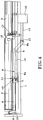
- Figure 1 a schematic elevational view of the articulated base in a horizontal position.
- FIGS 2 and 3 of the views showing the bed base of which the bust part is respectively in the intermediate position and in the maximum inclined position.
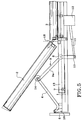
- Figure 4 an elevational view on a larger scale of another alternative embodiment of the hinged base in horizontal position and Figure 5 the same view with the bust part in an inclined position.
- FIG. 1 is a schematic illustration of a bed base according to the invention in which the sleeping part consists of a horizontal plane 3 capable of moving in translation on the fixed frame 1 of the bed and of a tilting part 2 articulated on the plane 3.
- a connecting rod 4 whose length is proportional to that of the tilting part 2 constituting the bust part, is articulated on the one hand on the fixed frame 1 at its headboard 6 and on the other hand on the tilting part substantially in its median zone, the articulation between the connecting rod and the tilting part being ensured at this point.
- the connecting rod 4 could be fixed to the pivoting member of the tilting part.
- a safety bar 5 is arranged at the foot of the bed, between the horizontal plane 3 and the frame 1 to prevent any incident, as will be shown below.
- FIG. 4 There is shown in more detail in FIG. 4 an articulation mechanism inspired by that shown diagrammatically in FIG. 1.
- the fixed frame 1 consists of the two longitudinal crosspieces of the bed, connected by non-visible transverse crosspieces.
- the headboard 6, also fixed, is integral with the chassis.
- a movable frame 13 which can move back and forth or vice versa, owing to the fact that it is mounted on rollers 7.
- a control bar 8 can pivot.
- the movable rod 11 of a jack 12 mounted on the movable frame 13 is connected to this end 10 of each stick.
- the end of the large arm 9a of each stick supports a roller 14 mounted idly on an axis 15.
- each connecting rod extends horizontally between the headboard and the movable frame 13 and keeps the latter separated as far as possible from the headboard.
- the horizontal plane 3 corresponding to the sleeping part which remains horizontal is fixed to the movable frame 13 at several points on its surface, in particular by the link 17.
- the tilting part 2 of the bed base is connected to the plane 3 by a set of articulations 18 and it rests on the rollers 14 mounted at the ends of the sticks 9.
- the rollers 14 could be replaced by sliding shoes.
- the entire sleeping part of the bed base, shown in FIG. 4, is therefore horizontal and the end of the tilting part 2 is in the immediate vicinity of the headboard 6.
- Figure 5 shows the box spring when the bust part is tilted.
- the user has ordered the actuation of the jack 12 whose rod 11 acts on the end 10 of the butt 9 ensuring the pivoting of the latter around its axis which constitutes the control bar 8.
- the upward movement of the arms 9a which results therefrom, raises the tilting part 2 by means of the rollers 14, part the end of which pivots relative to the plane 3 by means of the joints 18.
- the connecting rod 4 linked by its end to the butt 9 is also driven upwards by pivoting around the stem 16 and therefore exerts a traction on the butt having the effect of moving the movable frame 13 - and the whole of the sleeping part which it supports -, in the direction of the headboard 6.
- the movable frame rolls, thanks to its rollers 7, on the fixed frame 1.
Landscapes
- Health & Medical Sciences (AREA)
- General Health & Medical Sciences (AREA)
- Nursing (AREA)
- Invalid Beds And Related Equipment (AREA)
- Accommodation For Nursing Or Treatment Tables (AREA)
- Joints Allowing Movement (AREA)
- Forklifts And Lifting Vehicles (AREA)
- Massaging Devices (AREA)
- Sliding-Contact Bearings (AREA)
- Toys (AREA)
Abstract
Description
- L'invention porte sur un sommier articulé dont la partie buste au moins est susceptible de pivoter et de coulisser par rapport à un cadre fixe.
- Les sommiers articulés connus comportent un certain nombre de parties inclinables qui pivotent par rapport à un cadre fixe et par rapport à leurs parties voisines et qui permettent à la partie couchage de prendre des inclinaisons voulues en fonction de la position de relaxation recherchée. Les parties articulées sont mises en mouvement par un ou des moteurs électriques qui modifient leur orientation par l'intermédiaire de bielles et de leviers pivotants. L'usage le plus courant de ces sommiers consiste à relever la partie buste, c'est-à-dire la tête du sommier pour que l'utilisateur se trouve en position semi-assise lui facilitant par exemple la lecture. Mais le simple pivotement de cette partie buste par rapport au reste du sommier, qui relève l'utilisateur, l'éloigne systématiquement de la tête du lit, donc de l'éclairage, de la table de nuit, du téléphone etc...
- Afin de pallier à cet inconvénient la Demanderesse a mis au point un mécanisme qui permet à l'ensemble de la partie couchage de coulisser également par rapport au cadre fixe, au fur et à mesure de l'élévation de la partie buste de telle sorte que la tête de l'utilisateur reste toujours à proximité immédiate de la tête de lit, aussi bien en position allongée qu'en position assise.
- Un objet principal de la présente invention consiste donc en un sommier articulé dont la partie couchage comporte un plan horizontal et au moins une partie inclinable articulée sur ledit plan horizontal, manoeuvrée par au moins un moteur qui modifie son orientation par l'intermédiaire de bielles et/ou de leviers pivotants, sommier selon lequel au moins une bielle est articulée sur le châssis fixe du sommier, est en appui par son extrémité opposée sur la partie inclinable du couchage constituant la partie buste, l'ensemble de la partie couchage qui se déplace en translation sur le châssis fixe étant raccordé à l'extrémité de la bielle et un organe moteur commandant le pivotement de la bielle et de la partie inclinable du couchage, ainsi que le déplacement de l'ensemble de la partie couchage en direction de la tête de lit.
- Selon une première variante de réalisation, l'extrémité de la bielle est en appui sur la partie inclinable, sensiblement dans sa zone médiane et elle est articulée avec ladite partie inclinable en ce point.
- Selon une autre variante de réalisation, le plan horizontal de la partie couchage repose sur un châssis mobile en translation sur le châssis fixe, au moins une crosse reliant l'extrémité de chaque bielle au châssis mobile et chaque extrémité de la bielle portant un galet de roulement sur lequel repose la partie inclinable du couchage.
- Avantageusement, une crosse est fixée à chaque extrémité d'une barre de commande pivotante s'étendant transversalement au châssis mobile et l'extrémité du grand bras de la crosse tourillonne sur l'extrémité de la bielle, tandis que sur l'extrémité du petit bras de la crosse qui s'étend en sens inverse vers le bas est raccordée la tige d'un vérin monté sur le châssis fixe qui constitue l'organe moteur du pivotement de la bielle.
- Les caractéristiques particulières et avantages de l'invention ressortiront de la description qui va suivre d'exemples de réalisation dans lesquels il sera fait référence aux dessins annexés qui représentent :
- Figure 1 une vue schématique en élévation du sommier articulé en position horizontale.
- Figures 2 et 3 des vues montrant le sommier dont la partie buste est respectivement en position intermédiaire et en position inclinée maximum.
- Figure 4 une vue en élévation à plus grande échelle d'une autre variante de réalisation de sommier articulé en position horizontale et figure 5 la même vue avec la partie buste en position inclinée.
- La figure 1 est une illustration schématique d'un sommier selon l'invention dans lequel la partie couchage est constituée d'un plan horizontal 3 susceptible de se déplacer en translation sur le châssis fixe 1 du lit et d'une partie inclinable 2 articulée sur le plan 3. Une bielle de liaison 4 dont la longueur est proportionnée à celle de la partie inclinable 2 constituant la partie buste, est articulée d'une part sur le châssis fixe 1 au niveau de sa tête de lit 6 et d'autre part sur la partie inclinable sensiblement dans sa zone médiane, l'articulation entre la bielle et la partie inclinable étant assurée en ce point. En variante, la bielle de liaison 4 pourrait être fixée à l'organe de pivotement de la partie inclinable. Une barre de sécurité 5 est disposée au pied du lit, entre le plan horizontal 3 et le châssis 1 pour prévenir tout incident, comme on le montrera plus loin. On voit clairement aux figures 2 et 3 que lors de l'inclinaison de la partie buste 2, du fait de la bielle 4, le plan horizontal 3 de couchage ainsi que la partie buste, se déplacent en translation en s'éloignant du pied de lit, ce qui a pour effet que l'extrémité supérieure de la partie buste reste à la même distance de la tête de lit quel que soit son degré d'inclinaison.
- On a représenté plus en détail à la figure 4 un mécanisme d'articulation inspiré de celui schématisé à la figure 1. Le châssis fixe 1 est constitué des deux traverses longitudinales du lit, reliées par des traverses transversales non visibles. La tête de lit 6 également fixe est solidaire du châssis.
- Au-dessus du châssis fixe 1, repose un châssis mobile 13 pouvant se déplacer d'avant en arrière ou inversement, du fait qu'il est monté sur des galets de roulement 7. Sur ledit châssis mobile est montée, transversalement entre ses deux longerons longitudinaux, une barre de commande 8 pouvant pivoter. A chaque extrémité de la barre est fixée une crosse 9 dont un grand bras 9a s'étend sensiblement horizontalement en direction de la tête de lit tandis que son petit bras 9b s'étend en sens inverse et vers le bas, son extrémité 10 débordant sous le châssis fixe 1. La tige mobile 11 d'un vérin 12 monté sur le châssis mobile 13 se raccorde à cette extrémité 10 de chaque crosse. L'extrémité du grand bras 9a de chaque crosse supporte un galet 14 monté fou sur un axe 15. Sur cet axe 15 tourillonne l'extrémité de la bielle de liaison 4 schématisée aux figures 1 à 3. Cette dernière a la forme d'une canne dont l'extrémité opposée s'articule sur une potence 16, solidaire du châssis fixe 1 à proximité immédiate de la tête de lit 6. Il y a donc deux bielles articulées à chacune des deux crosses latérales pivotantes. On voit à la figure 4 que chaque bielle s'étend horizontalement entre la tête de lit et le châssis mobile 13 et maintient ce dernier écarté au maximum de la tête de lit. Le plan horizontal 3 correspondant à la partie couchage qui reste horizontale est fixé au châssis mobile 13 en plusieurs points de sa surface notamment par la liaison 17. La partie inclinable 2 du sommier est reliée au plan 3 par un jeu d'articulations 18 et elle repose sur les galets 14 montés aux extrémités des crosses 9. En variante, les galets 14 pourraient être remplacés par des patins de glissement. L'ensemble de la partie couchage du sommier, représentée à la figure 4, est donc horizontal et le bout de la partie inclinable 2 se trouve à proximité immédiate de la tête de lit 6.
- La figure 5 montre le sommier quand la partie buste est inclinée. Pour passer à cette position, l'utilisateur a commandé la manoeuvre du vérin 12 dont la tige 11 agit sur l'extrémité 10 de la crosse 9 assurant le pivotement de celle-ci autour de son axe que constitue la barre de commande 8. Le mouvement ascendant des bras 9a, qui en résulte, soulève la partie inclinable 2 par l'intermédiaire des galets 14, partie dont l'extrémité pivote par rapport au plan 3 grâce aux articulations 18. Au cours de ce pivotement la bielle 4, liée par son extrémité à la crosse 9, est entraînée aussi vers le haut en pivotant autour de la potence 16 et exerce de ce fait une traction sur la crosse ayant pour effet de déplacer le châssis mobile 13 - et l'ensemble de la partie couchage qu'il supporte -, en direction de la tête de lit 6. Pour cela le châssis mobile roule, grâce à ses galets 7, sur le châssis fixe 1.
- Dans la position représentée, on voit que la partie haute inclinée 2 s'est donc déplacée et son extrémité se trouve à proximité immédiate de la tête de lit 6, comme lorsque le couchage est en position horizontale. L'utilisateur reste ainsi à proximité des éclairages et tables de chevet.
- On voit à la figure 3 que dans la position buste incliné, le plan horizontal 3 s'est écarté du pied de lit, laissant un creux entre le couchage et le fond. Si un objet quelconque se trouvait déposé dans ce creux, il constituerait un obstacle à la remise en place du sommier en position horizontale. La barre de sécurité 5 mentionnée plus haut serait alors soumise à une pression exercée par l'objet repoussé par le lit et commanderait alors un contacteur qui inverse le sens d'action du vérin ou du moteur. Il n'y a donc pas de risque de détérioration de l'objet ni du lit, ni du mécanisme.
- Pour revenir à cette position horizontale on effectue la manoeuvre inverse à partir du vérin 12.
Claims (7)
Applications Claiming Priority (2)
| Application Number | Priority Date | Filing Date | Title |
|---|---|---|---|
| FR9404633 | 1994-04-19 | ||
| FR9404633A FR2718621B1 (fr) | 1994-04-19 | 1994-04-19 | Sommier articulé à pivotement et coulissement. |
Publications (2)
| Publication Number | Publication Date |
|---|---|
| EP0678261A1 true EP0678261A1 (fr) | 1995-10-25 |
| EP0678261B1 EP0678261B1 (fr) | 1998-12-30 |
Family
ID=9462236
Family Applications (1)
| Application Number | Title | Priority Date | Filing Date |
|---|---|---|---|
| EP95400813A Expired - Lifetime EP0678261B1 (fr) | 1994-04-19 | 1995-04-11 | Sommier articulé à pivotement et coulissement |
Country Status (7)
| Country | Link |
|---|---|
| EP (1) | EP0678261B1 (fr) |
| AT (1) | ATE175083T1 (fr) |
| DE (1) | DE69506933T2 (fr) |
| DK (1) | DK0678261T3 (fr) |
| ES (1) | ES2128004T3 (fr) |
| FR (1) | FR2718621B1 (fr) |
| GR (1) | GR3029676T3 (fr) |
Cited By (5)
| Publication number | Priority date | Publication date | Assignee | Title |
|---|---|---|---|---|
| WO1997030614A1 (fr) * | 1996-02-20 | 1997-08-28 | Niagara Manufacturing Ltd. | Lit ajustable |
| EP1525824A1 (fr) * | 2003-10-23 | 2005-04-27 | Oniris | Mécanisme pour sommier articulé |
| EP0884011B2 (fr) † | 1997-05-23 | 2007-09-12 | Thomas Beteiligungs- und Vermögens GmbH & Co. KG | Assemblage de lattes particulièrement pour un sommier |
| DE102008064096A1 (de) | 2008-12-19 | 2010-07-15 | Klaus Bock | Liegeflächeneinrichtung für ein Bett |
| BE1027540B1 (nl) * | 2019-09-02 | 2021-03-29 | Global Technical Equipment Bvba | Verstelbare bedinrichting omvattende een verplaatsbaar frame |
Families Citing this family (3)
| Publication number | Priority date | Publication date | Assignee | Title |
|---|---|---|---|---|
| DE202009003977U1 (de) | 2009-03-24 | 2009-07-30 | Horst E. Otten Matratzenfabrik Gmbh | Verstellmechanik, insbesondere für Lattenroste und Betten |
| DE102009014124A1 (de) | 2009-03-24 | 2010-10-07 | Horst E. Otten Matratzenfabrik Gmbh | Verstellmechanik, insbesondere für Lattenroste und Betten |
| DE102009016713A1 (de) | 2009-04-09 | 2010-10-14 | Horst E. Otten Matratzenfabrik Gmbh | Symmetrischer Unterbau für verstellbare Liegemöbel |
Citations (2)
| Publication number | Priority date | Publication date | Assignee | Title |
|---|---|---|---|---|
| FR1439800A (fr) | 1965-04-23 | 1966-05-20 | Cadre de lit | |
| GB2124896A (en) | 1982-08-11 | 1984-02-29 | Ronald Frank Morrison | Apparatus primarily for altering the attitude of a mattress on a bed |
-
1994
- 1994-04-19 FR FR9404633A patent/FR2718621B1/fr not_active Expired - Lifetime
-
1995
- 1995-04-11 EP EP95400813A patent/EP0678261B1/fr not_active Expired - Lifetime
- 1995-04-11 DK DK95400813T patent/DK0678261T3/da active
- 1995-04-11 AT AT95400813T patent/ATE175083T1/de active
- 1995-04-11 DE DE69506933T patent/DE69506933T2/de not_active Expired - Lifetime
- 1995-04-11 ES ES95400813T patent/ES2128004T3/es not_active Expired - Lifetime
-
1999
- 1999-03-12 GR GR990400760T patent/GR3029676T3/el unknown
Patent Citations (2)
| Publication number | Priority date | Publication date | Assignee | Title |
|---|---|---|---|---|
| FR1439800A (fr) | 1965-04-23 | 1966-05-20 | Cadre de lit | |
| GB2124896A (en) | 1982-08-11 | 1984-02-29 | Ronald Frank Morrison | Apparatus primarily for altering the attitude of a mattress on a bed |
Cited By (7)
| Publication number | Priority date | Publication date | Assignee | Title |
|---|---|---|---|---|
| WO1997030614A1 (fr) * | 1996-02-20 | 1997-08-28 | Niagara Manufacturing Ltd. | Lit ajustable |
| EP0884011B2 (fr) † | 1997-05-23 | 2007-09-12 | Thomas Beteiligungs- und Vermögens GmbH & Co. KG | Assemblage de lattes particulièrement pour un sommier |
| EP1525824A1 (fr) * | 2003-10-23 | 2005-04-27 | Oniris | Mécanisme pour sommier articulé |
| FR2861269A1 (fr) * | 2003-10-23 | 2005-04-29 | Oniris | Mecanisme pour sommier articule |
| DE102008064096A1 (de) | 2008-12-19 | 2010-07-15 | Klaus Bock | Liegeflächeneinrichtung für ein Bett |
| DE102008064096B4 (de) * | 2008-12-19 | 2010-09-02 | Klaus Bock | Liegeflächeneinrichtung für ein Bett |
| BE1027540B1 (nl) * | 2019-09-02 | 2021-03-29 | Global Technical Equipment Bvba | Verstelbare bedinrichting omvattende een verplaatsbaar frame |
Also Published As
| Publication number | Publication date |
|---|---|
| DE69506933T2 (de) | 1999-07-29 |
| GR3029676T3 (en) | 1999-06-30 |
| ATE175083T1 (de) | 1999-01-15 |
| DE69506933D1 (de) | 1999-02-11 |
| DK0678261T3 (da) | 1999-08-30 |
| FR2718621B1 (fr) | 1996-06-21 |
| ES2128004T3 (es) | 1999-05-01 |
| FR2718621A1 (fr) | 1995-10-20 |
| EP0678261B1 (fr) | 1998-12-30 |
Similar Documents
| Publication | Publication Date | Title |
|---|---|---|
| WO1996012427A1 (fr) | Dispositif d'inclinaison de tete et/ou de pied de lit | |
| FR2717377A1 (fr) | Dispositif-élévateur pour fauteuil roulant verticalisateur et fauteuil roulant en faisant application. | |
| EP0678261A1 (fr) | Sommier articulé à pivotement et coulissement | |
| EP0774223B1 (fr) | Sommier déformable à profil ergonomique | |
| EP0183630A1 (fr) | Siège transformable | |
| FR2780256A1 (fr) | Sommier de lit reglable | |
| FR2671468A1 (fr) | Sommier a dossier relevable et matelas adapte. | |
| FR2651978A1 (fr) | Cadre de matelas comportant un appui pour les jambes articule et reglable. | |
| FR2899779A1 (fr) | Cadre de lit articule | |
| EP1372433B1 (fr) | Lit muni d'un releve-dos | |
| EP1525824A1 (fr) | Mécanisme pour sommier articulé | |
| WO1997029725A1 (fr) | Fauteuil elevateur motorise | |
| FR2799107A1 (fr) | Sommier a lattes pour lits, divans ou similaires | |
| FR2670374A1 (fr) | Mecanisme de relevage pour sommier articule. | |
| FR2711521A1 (fr) | Lit pour malade. | |
| EP0895738B1 (fr) | Sommier déformable à profil déclive et ergonomique | |
| BE1016140A3 (fr) | Armature de fauteuil siege/couchette avec mecanisme a genouilleres. | |
| EP1016360B1 (fr) | Lit avec sommier articulé | |
| FR2712802A1 (fr) | Fauteuil élévateur motorisé. | |
| FR2755358A1 (fr) | Mecanisme d'articulation des parties inclinables d'un sommier | |
| EP1281339A1 (fr) | Sommier de relaxation à tête et pied relevable | |
| FR2695813A1 (fr) | Siège assurant l'aide au lever d'une personne à mobilité réduite à partir de la position assise. | |
| EP2014198B1 (fr) | Sommier de literie déployable et lit comprenant un tel sommier | |
| FR2780257A1 (fr) | Sommier de lit reglable | |
| EP1767123B1 (fr) | Plan de couchage ayant une portion de plan intermédiaire |
Legal Events
| Date | Code | Title | Description |
|---|---|---|---|
| PUAI | Public reference made under article 153(3) epc to a published international application that has entered the european phase |
Free format text: ORIGINAL CODE: 0009012 |
|
| AK | Designated contracting states |
Kind code of ref document: A1 Designated state(s): AT BE CH DE DK ES GB GR IT LI LU NL PT |
|
| 17P | Request for examination filed |
Effective date: 19960318 |
|
| 17Q | First examination report despatched |
Effective date: 19970402 |
|
| GRAG | Despatch of communication of intention to grant |
Free format text: ORIGINAL CODE: EPIDOS AGRA |
|
| GRAG | Despatch of communication of intention to grant |
Free format text: ORIGINAL CODE: EPIDOS AGRA |
|
| GRAH | Despatch of communication of intention to grant a patent |
Free format text: ORIGINAL CODE: EPIDOS IGRA |
|
| GRAH | Despatch of communication of intention to grant a patent |
Free format text: ORIGINAL CODE: EPIDOS IGRA |
|
| GRAA | (expected) grant |
Free format text: ORIGINAL CODE: 0009210 |
|
| AK | Designated contracting states |
Kind code of ref document: B1 Designated state(s): AT BE CH DE DK ES GB GR IT LI LU NL PT |
|
| REF | Corresponds to: |
Ref document number: 175083 Country of ref document: AT Date of ref document: 19990115 Kind code of ref document: T |
|
| REG | Reference to a national code |
Ref country code: CH Ref legal event code: EP |
|
| 111L | Licence recorded |
Free format text: 980825 0100 TRECA, SOCIETE ANONYME * 980825 0101 TRECA BENELUX, SOCIETE ANONYME * 980825 0102 TRECA DE ESPANA, SOCIETE ANONYME * 980825 0103 TRECA GMBH * 980825 0104 TRECA SA, SOCIETE ANONYME * 980825 0105 TRECA SRL, SRL |
|
| REF | Corresponds to: |
Ref document number: 69506933 Country of ref document: DE Date of ref document: 19990211 |
|
| ITF | It: translation for a ep patent filed | ||
| REG | Reference to a national code |
Ref country code: CH Ref legal event code: NV Representative=s name: DIETLIN & CIE S.A. |
|
| GBT | Gb: translation of ep patent filed (gb section 77(6)(a)/1977) |
Effective date: 19990324 |
|
| REG | Reference to a national code |
Ref country code: ES Ref legal event code: FG2A Ref document number: 2128004 Country of ref document: ES Kind code of ref document: T3 |
|
| REG | Reference to a national code |
Ref country code: PT Ref legal event code: SC4A Free format text: AVAILABILITY OF NATIONAL TRANSLATION Effective date: 19990317 |
|
| REG | Reference to a national code |
Ref country code: DK Ref legal event code: T3 |
|
| PLBE | No opposition filed within time limit |
Free format text: ORIGINAL CODE: 0009261 |
|
| STAA | Information on the status of an ep patent application or granted ep patent |
Free format text: STATUS: NO OPPOSITION FILED WITHIN TIME LIMIT |
|
| 26N | No opposition filed | ||
| REG | Reference to a national code |
Ref country code: GB Ref legal event code: IF02 |
|
| PGFP | Annual fee paid to national office [announced via postgrant information from national office to epo] |
Ref country code: ES Payment date: 20120425 Year of fee payment: 18 |
|
| PGFP | Annual fee paid to national office [announced via postgrant information from national office to epo] |
Ref country code: AT Payment date: 20120322 Year of fee payment: 18 |
|
| PGFP | Annual fee paid to national office [announced via postgrant information from national office to epo] |
Ref country code: DK Payment date: 20130318 Year of fee payment: 19 Ref country code: LU Payment date: 20130321 Year of fee payment: 19 |
|
| PGFP | Annual fee paid to national office [announced via postgrant information from national office to epo] |
Ref country code: GR Payment date: 20130327 Year of fee payment: 19 |
|
| PGFP | Annual fee paid to national office [announced via postgrant information from national office to epo] |
Ref country code: PT Payment date: 20130318 Year of fee payment: 19 |
|
| PGFP | Annual fee paid to national office [announced via postgrant information from national office to epo] |
Ref country code: GB Payment date: 20130415 Year of fee payment: 19 Ref country code: CH Payment date: 20130415 Year of fee payment: 19 Ref country code: BE Payment date: 20130430 Year of fee payment: 19 Ref country code: DE Payment date: 20130409 Year of fee payment: 19 |
|
| PGFP | Annual fee paid to national office [announced via postgrant information from national office to epo] |
Ref country code: NL Payment date: 20130313 Year of fee payment: 19 Ref country code: IT Payment date: 20130422 Year of fee payment: 19 |
|
| REG | Reference to a national code |
Ref country code: PT Ref legal event code: MM4A Free format text: LAPSE DUE TO NON-PAYMENT OF FEES Effective date: 20141013 |
|
| REG | Reference to a national code |
Ref country code: DE Ref legal event code: R119 Ref document number: 69506933 Country of ref document: DE |
|
| REG | Reference to a national code |
Ref country code: DK Ref legal event code: EBP Effective date: 20140430 |
|
| REG | Reference to a national code |
Ref country code: NL Ref legal event code: V1 Effective date: 20141101 |
|
| PG25 | Lapsed in a contracting state [announced via postgrant information from national office to epo] |
Ref country code: LU Free format text: LAPSE BECAUSE OF NON-PAYMENT OF DUE FEES Effective date: 20140411 |
|
| REG | Reference to a national code |
Ref country code: CH Ref legal event code: PL |
|
| REG | Reference to a national code |
Ref country code: AT Ref legal event code: MM01 Ref document number: 175083 Country of ref document: AT Kind code of ref document: T Effective date: 20140411 |
|
| GBPC | Gb: european patent ceased through non-payment of renewal fee |
Effective date: 20140411 |
|
| REG | Reference to a national code |
Ref country code: GR Ref legal event code: ML Ref document number: 990400760 Country of ref document: GR Effective date: 20141104 |
|
| PG25 | Lapsed in a contracting state [announced via postgrant information from national office to epo] |
Ref country code: GR Free format text: LAPSE BECAUSE OF NON-PAYMENT OF DUE FEES Effective date: 20141104 Ref country code: DE Free format text: LAPSE BECAUSE OF NON-PAYMENT OF DUE FEES Effective date: 20141101 Ref country code: PT Free format text: LAPSE BECAUSE OF NON-PAYMENT OF DUE FEES Effective date: 20141013 Ref country code: GB Free format text: LAPSE BECAUSE OF NON-PAYMENT OF DUE FEES Effective date: 20140411 Ref country code: CH Free format text: LAPSE BECAUSE OF NON-PAYMENT OF DUE FEES Effective date: 20140430 Ref country code: LI Free format text: LAPSE BECAUSE OF NON-PAYMENT OF DUE FEES Effective date: 20140430 |
|
| REG | Reference to a national code |
Ref country code: DE Ref legal event code: R119 Ref document number: 69506933 Country of ref document: DE Effective date: 20141101 |
|
| PG25 | Lapsed in a contracting state [announced via postgrant information from national office to epo] |
Ref country code: NL Free format text: LAPSE BECAUSE OF NON-PAYMENT OF DUE FEES Effective date: 20141101 Ref country code: AT Free format text: LAPSE BECAUSE OF NON-PAYMENT OF DUE FEES Effective date: 20140411 |
|
| PG25 | Lapsed in a contracting state [announced via postgrant information from national office to epo] |
Ref country code: IT Free format text: LAPSE BECAUSE OF NON-PAYMENT OF DUE FEES Effective date: 20140411 |
|
| REG | Reference to a national code |
Ref country code: PT Ref legal event code: MM4A Free format text: MAXIMUM VALIDITY LIMIT REACHED Effective date: 20150411 |
|
| PG25 | Lapsed in a contracting state [announced via postgrant information from national office to epo] |
Ref country code: DK Free format text: LAPSE BECAUSE OF NON-PAYMENT OF DUE FEES Effective date: 20140430 |
|
| REG | Reference to a national code |
Ref country code: ES Ref legal event code: FD2A Effective date: 20150528 |
|
| PG25 | Lapsed in a contracting state [announced via postgrant information from national office to epo] |
Ref country code: PT Free format text: LAPSE BECAUSE OF EXPIRATION OF PROTECTION Effective date: 20150421 Ref country code: ES Free format text: LAPSE BECAUSE OF NON-PAYMENT OF DUE FEES Effective date: 20140412 |
|
| PG25 | Lapsed in a contracting state [announced via postgrant information from national office to epo] |
Ref country code: PT Free format text: LAPSE BECAUSE OF EXPIRATION OF PROTECTION Effective date: 20140411 |
|
| PG25 | Lapsed in a contracting state [announced via postgrant information from national office to epo] |
Ref country code: BE Free format text: LAPSE BECAUSE OF NON-PAYMENT OF DUE FEES Effective date: 20140430 |