EP0678149B1 - Verfahren zum Verstärken von Mauerwerkswänden - Google Patents
Verfahren zum Verstärken von Mauerwerkswänden Download PDFInfo
- Publication number
- EP0678149B1 EP0678149B1 EP92910084A EP92910084A EP0678149B1 EP 0678149 B1 EP0678149 B1 EP 0678149B1 EP 92910084 A EP92910084 A EP 92910084A EP 92910084 A EP92910084 A EP 92910084A EP 0678149 B1 EP0678149 B1 EP 0678149B1
- Authority
- EP
- European Patent Office
- Prior art keywords
- annulus
- hole
- drill bit
- dust
- further characterized
- Prior art date
- Legal status (The legal status is an assumption and is not a legal conclusion. Google has not performed a legal analysis and makes no representation as to the accuracy of the status listed.)
- Expired - Lifetime
Links
- 238000000034 method Methods 0.000 title claims description 27
- 230000003014 reinforcing effect Effects 0.000 title claims description 4
- 239000000428 dust Substances 0.000 claims abstract description 29
- 238000005553 drilling Methods 0.000 claims abstract description 23
- 239000011443 resin grout Substances 0.000 claims description 8
- 230000002787 reinforcement Effects 0.000 claims description 7
- 230000006378 damage Effects 0.000 claims description 5
- 239000000463 material Substances 0.000 claims description 3
- 239000004809 Teflon Substances 0.000 claims description 2
- 229920006362 Teflon® Polymers 0.000 claims description 2
- 230000008878 coupling Effects 0.000 claims description 2
- 238000010168 coupling process Methods 0.000 claims description 2
- 238000005859 coupling reaction Methods 0.000 claims description 2
- 239000004033 plastic Substances 0.000 abstract description 24
- 238000005520 cutting process Methods 0.000 abstract description 10
- 230000000284 resting effect Effects 0.000 abstract 1
- 229910000831 Steel Inorganic materials 0.000 description 28
- 239000010959 steel Substances 0.000 description 28
- 239000011449 brick Substances 0.000 description 8
- 238000012856 packing Methods 0.000 description 5
- 239000011435 rock Substances 0.000 description 5
- 229910003460 diamond Inorganic materials 0.000 description 4
- 239000010432 diamond Substances 0.000 description 4
- 239000011347 resin Substances 0.000 description 3
- 229920005989 resin Polymers 0.000 description 3
- 239000004567 concrete Substances 0.000 description 2
- 238000001816 cooling Methods 0.000 description 2
- 238000001514 detection method Methods 0.000 description 2
- 239000004570 mortar (masonry) Substances 0.000 description 2
- 238000007789 sealing Methods 0.000 description 2
- 230000036346 tooth eruption Effects 0.000 description 2
- 229910001294 Reinforcing steel Inorganic materials 0.000 description 1
- 230000003796 beauty Effects 0.000 description 1
- 238000000605 extraction Methods 0.000 description 1
- 239000011451 fired brick Substances 0.000 description 1
- 238000009472 formulation Methods 0.000 description 1
- 238000005065 mining Methods 0.000 description 1
- 239000000203 mixture Substances 0.000 description 1
- 238000012986 modification Methods 0.000 description 1
- 230000004048 modification Effects 0.000 description 1
- 238000005457 optimization Methods 0.000 description 1
- 230000035939 shock Effects 0.000 description 1
- 239000003381 stabilizer Substances 0.000 description 1
- 238000010186 staining Methods 0.000 description 1
- 230000000153 supplemental effect Effects 0.000 description 1
- UONOETXJSWQNOL-UHFFFAOYSA-N tungsten carbide Chemical compound [W+]#[C-] UONOETXJSWQNOL-UHFFFAOYSA-N 0.000 description 1
- XLYOFNOQVPJJNP-UHFFFAOYSA-N water Substances O XLYOFNOQVPJJNP-UHFFFAOYSA-N 0.000 description 1
- 238000005303 weighing Methods 0.000 description 1
Images


Classifications
-
- E—FIXED CONSTRUCTIONS
- E04—BUILDING
- E04G—SCAFFOLDING; FORMS; SHUTTERING; BUILDING IMPLEMENTS OR AIDS, OR THEIR USE; HANDLING BUILDING MATERIALS ON THE SITE; REPAIRING, BREAKING-UP OR OTHER WORK ON EXISTING BUILDINGS
- E04G23/00—Working measures on existing buildings
- E04G23/02—Repairing, e.g. filling cracks; Restoring; Altering; Enlarging
- E04G23/0218—Increasing or restoring the load-bearing capacity of building construction elements
-
- B—PERFORMING OPERATIONS; TRANSPORTING
- B28—WORKING CEMENT, CLAY, OR STONE
- B28D—WORKING STONE OR STONE-LIKE MATERIALS
- B28D1/00—Working stone or stone-like materials, e.g. brick, concrete or glass, not provided for elsewhere; Machines, devices, tools therefor
- B28D1/02—Working stone or stone-like materials, e.g. brick, concrete or glass, not provided for elsewhere; Machines, devices, tools therefor by sawing
- B28D1/04—Working stone or stone-like materials, e.g. brick, concrete or glass, not provided for elsewhere; Machines, devices, tools therefor by sawing with circular or cylindrical saw-blades or saw-discs
- B28D1/041—Working stone or stone-like materials, e.g. brick, concrete or glass, not provided for elsewhere; Machines, devices, tools therefor by sawing with circular or cylindrical saw-blades or saw-discs with cylinder saws, e.g. trepanning; saw cylinders, e.g. having their cutting rim equipped with abrasive particles
-
- E—FIXED CONSTRUCTIONS
- E21—EARTH OR ROCK DRILLING; MINING
- E21B—EARTH OR ROCK DRILLING; OBTAINING OIL, GAS, WATER, SOLUBLE OR MELTABLE MATERIALS OR A SLURRY OF MINERALS FROM WELLS
- E21B10/00—Drill bits
- E21B10/02—Core bits
- E21B10/04—Core bits with core destroying means
-
- E—FIXED CONSTRUCTIONS
- E21—EARTH OR ROCK DRILLING; MINING
- E21B—EARTH OR ROCK DRILLING; OBTAINING OIL, GAS, WATER, SOLUBLE OR MELTABLE MATERIALS OR A SLURRY OF MINERALS FROM WELLS
- E21B21/00—Methods or apparatus for flushing boreholes, e.g. by use of exhaust air from motor
- E21B21/12—Methods or apparatus for flushing boreholes, e.g. by use of exhaust air from motor using drilling pipes with plural fluid passages, e.g. closed circulation systems
-
- E—FIXED CONSTRUCTIONS
- E21—EARTH OR ROCK DRILLING; MINING
- E21B—EARTH OR ROCK DRILLING; OBTAINING OIL, GAS, WATER, SOLUBLE OR MELTABLE MATERIALS OR A SLURRY OF MINERALS FROM WELLS
- E21B21/00—Methods or apparatus for flushing boreholes, e.g. by use of exhaust air from motor
- E21B21/16—Methods or apparatus for flushing boreholes, e.g. by use of exhaust air from motor using gaseous fluids
-
- Y—GENERAL TAGGING OF NEW TECHNOLOGICAL DEVELOPMENTS; GENERAL TAGGING OF CROSS-SECTIONAL TECHNOLOGIES SPANNING OVER SEVERAL SECTIONS OF THE IPC; TECHNICAL SUBJECTS COVERED BY FORMER USPC CROSS-REFERENCE ART COLLECTIONS [XRACs] AND DIGESTS
- Y10—TECHNICAL SUBJECTS COVERED BY FORMER USPC
- Y10T—TECHNICAL SUBJECTS COVERED BY FORMER US CLASSIFICATION
- Y10T408/00—Cutting by use of rotating axially moving tool
- Y10T408/44—Cutting by use of rotating axially moving tool with means to apply transient, fluent medium to work or product
- Y10T408/45—Cutting by use of rotating axially moving tool with means to apply transient, fluent medium to work or product including Tool with duct
- Y10T408/455—Conducting channel extending to end of Tool
-
- Y—GENERAL TAGGING OF NEW TECHNOLOGICAL DEVELOPMENTS; GENERAL TAGGING OF CROSS-SECTIONAL TECHNOLOGIES SPANNING OVER SEVERAL SECTIONS OF THE IPC; TECHNICAL SUBJECTS COVERED BY FORMER USPC CROSS-REFERENCE ART COLLECTIONS [XRACs] AND DIGESTS
- Y10—TECHNICAL SUBJECTS COVERED BY FORMER USPC
- Y10T—TECHNICAL SUBJECTS COVERED BY FORMER US CLASSIFICATION
- Y10T408/00—Cutting by use of rotating axially moving tool
- Y10T408/89—Tool or Tool with support
- Y10T408/895—Having axial, core-receiving central portion
Definitions
- This invention relates to a technique developed for coring masonry walls or the like, with less optimal, but adequate ability to core concrete and steel.
- the method of reinforcement has generally been a technique which involves drilling long vertical holes through the masonry walls, inserting steel reinforcement bars, and grouting the bars in place with resin grout to provide the necessary reinforcement against seismic destruction. Because of the peculiar nature of drilling in an urban environment in what are often historic buildings and the final use of resin in the drill holes, there are several constraints placed upon such techniques.
- the first constraint is that the holes which are to be drilled for long distances, which can be up to 30,48 m (100 feet) in depth, must be straight so that they do not exit the side of the wall while drilling and further, that they are well-centered for structural optimization. Secondly, since the friction of the drilling process is substantial, an adequate method of cooling the bit is necessary.
- FR-A-2 635 550 discloses a method for reinforcing a masonry wall for supplemental floors of an existing building, this method, which is also suitable for reinforcing walls against seismic destruction, comprising the steps of rotating a drill bit on a drill shaft and coring a hole in the masonry wall producing a limited amount of drilling dust, placing a reinforcing steel bar in the hole and filling this hole with resin grout.
- US-A-3 655 001 discloses a system for producing large-diameter, air-drilled holes through rock comprising a hollow, rotatable drill stem having a large bit at its lower end, and surrounded by a pipe which is relatively narrow compared to the hole diameter, which forms between itself and the drill stem, an annular passage. Air is blown downwardly through the drill stem, emerges at an opening at the location of the bit, and carries cuttings through the annular passage to the surface. A vacuum is drawn in a dust diverter immediately above the bit to insure that the cuttings enter the annular passage. Air descending through the drill stem under pressure operates a piston which imparts a hammering action to the bit. Drill stem sections and outer pipe sections may be added as required.
- the present invention provides a substantially improved masonry coring technique which eliminates the problems associated with the coring of masonry walls.
- the system comprises a drill bit, which is simply a tube of steel with carbide and/or diamond teeth mounted at its lower end for cutting a core in the masonry.
- the steel tube can be from about 76,2 bis 305 mm (3 to 12 inches) in diameter.
- Inside the steel tube is a core breaker which conveniently can be a small version of a rotary cone rock bit which pulverizes the core.
- the bit and the core breaker are driven by a rotatable steel shaft threaded into a driver plate located at the top of the drill bit.
- the core breaker and the bit are also threaded onto the driver plate.
- the shaft is rotated at a controlled speed by hydraulic motors. Controlled downward force is hand-controlled or may be automated. The bit can be kept in alignment since the shaft is quite stiff and the downward force and rotational speeds are kept low. Compressed air is forced down a small diameter axial hole in the steel shaft and exits through and around the core breaker. Air from inside the core drill flows past the teeth at the bottom and up the annulus between the core drill and the side of the hole being drilled. Air cools the teeth and carries out the ground masonry dust.
- the system further includes a plastic pipe which has an interior diameter slightly larger than the steel shaft and is placed around the steel shaft.
- the plastic pipe does not rotate but simply rides on top of the driver plate.
- the annulus between the top of the plastic pipe and the hole being drilled is closed with a low-friction collar, or a packing. Air from the annulus around the plastic pipe enters the annulus between the inside of the pipe and the steel shaft through a series of holes located near the bottom of the plastic pipe.
- the annulus between the plastic pipe and the steel shaft is closed with a packing.
- This annulus is connected to the suction side of an ejector to draw a suction on the annulus.
- the ejector output goes into a dust collector.
- the suction also is of great assistance in providing dust control. Additionally, it lowers the pressure around the drill bit, and particularly around the plastic pipe. This reduces air leakage through cracks or the like in the wall being drilled.
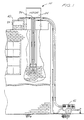
- FIG. 1 is a diagrammatical illustration of a masonry coring system 10 in operation.
- the coring system is comprised of a drill bit 12, which is a tube of steel with carbide and/or diamond teeth 14 mounted at its lower end for cutting a core in the masonry.
- the drill bit can range in size from about 76,2 to 304,8 mm (3 to 12 inches) in diameter.
- a 101,6 mm (four-inch) diameter is typical for most wall reinforcements.
- the steel tube preferably has a 9,6 mm (3/8 inch) wall thickness. The length of the steel tube is several times the diameter of the tube which enables the drill bit to act as a stabilizer and maintain a straight hole while cutting.
- the teeth are wider than the wall thickness of the steel tube and have a beveled cutting surface 16 which extends beyond the lower surface of the steel tube.
- the teeth can be mounted on the steel tube at various angles depending upon their intended use. Typically, the teeth are at a rake angle of from 5 to 15°.
- the upper end of the steel tube is threaded onto a steel driver plate 18.
- the threads are standard Acme square thread.
- the core breaker 26 Located within the steel tube is the core breaker 26 which is discussed in more detail later.
- the drill bit and the core breaker are driven by a rotatable steel driver shaft 20 which is approximately 47,6 mm (1-7/8 inch) in diameter.
- a driver shaft comes in 1,22 m (4-foot) sections with each section weighing approximately 13,6 kg (30 lbs).
- On opposite ends of each driver shaft are a male and a female thread so that the driver shafts can be threaded together as the drill bit works its way down the wall.
- the initial driver shaft is threaded into the driver plate.
- located within the driver shaft is a small diameter axial hole 22, approximately 6,35 bis 12,7 mm (1/4 to 1/2 inch). The hole exists so that compressed air can be forced through the driver shaft.
- Another reason for the axial hole being of a small diameter is so that the driver shaft can maintain a thick wall for added weight and rigidity so that it can withstand the torque applied to it and remain straight in the hole.
- the shaft is rotated at a controlled variable speed and with controlled downward force by a conventional hydraulic motor 24 of the same type previously used for wet drilling.
- the drill core is also capable of being maintained true and straight by keeping the downward force and the rotational speeds at a low level.
- a slow rotational speed is also necessary when using carbide teeth for dust control.
- a hydraulic motor is an ideal power source for controlling the amount of torque applied to the driver shaft.
- the actual speeds and downward force used depend on the type of material being drilled (concrete, soft brick, hard-fired brick, etc.) and the depth of the hole. Speeds range from 650 rpm for soft brick down to 350 rpm for hard brick. No additional force is applied to the drill bit beyond the weight of the bit and the drive shaft.
- a core breaker 26 located within the steel tube of the drill bit is a core breaker 26.
- the upper end of the core breaker is threaded into and driven by the driver plate.
- the core breaker conveniently may be a small version of a conventional three rotary cone rock bit which pulverizes the core as the bit cuts the hole.
- Such milled tooth, air cooled rock bits are commonly used for drilling blast holes in mining and quarrying operations.
- a plastic pipe 28 with inner diameter just larger than the shaft is placed around the steel driver shaft. This creates approximately a 3,2 mm (1/8-inch) annulus between the plastic pipe and the driver shaft through which the pulverized masonry is removed.
- the plastic pipe does not rotate but simply rides on top of the driver plate.
- a Teflon ring 30 is placed between the driver plate and the bottom of the plastic pipe so that the plastic pipe will not be worn down due to the rotating driver plate.
- the plastic pipe is preferably made of a schedule 80 PVC.
- the annulus between the plastic pipe and the steel shaft is closed with a packing.
- This annulus is connected to the suction side of a Venturi ejector 36 to draw a suction on the annulus.
- the pulverized core and the drilling dust is drawn through the annulus by the ejector and into a dust collector 38 which normally is a bag located within a 55 gallon drum 40.
- an air compressor 42 used to force compressed air through the small axial hole in the drive shaft as well as operate the ejector.
- the hydraulic motor rotates the drive shaft which, in turn, rotates the driver plate and the drill bit.
- the carbide and/or diamond teeth cut a cylindrical hole through the brick.
- the core thus created by the drill bit is pulverized by the three rotary cone rock bit.
- Compressed air is forced down the small axial hole in the steel drive shaft and exits through and around the core breaker. Air from inside the core drill flows past the teeth at the bottom of the drill bit and up the annulus between the core drill and the side of the hole being drilled. This air cools the teeth and carries out the ground masonry. The amount of compressed air that is forced down the hole in the drive shaft must be sufficient to carry out the ground masonry but not too excessive such that it would dislodge the mortar between the bricks. Applicant has found that between 620,5 bis 724 x 10 3 N/m 2 (90 and 105 psi) of air pressure at the top of the wall is sufficient for drilling about the first 12,2 m (40 feet), and then the pressure is slightly increased beyond that level.
- the annulus between the top of the plastic pipe and the hole being drilled is closed with a packing.
- the compressed air that has now exited around the drill bit and into the annulus between the drill bit and the hole being drilled then enters into the annulus between the plastic pipe and the drive shaft through the series of holes near the bottom of the plastic pipe.
- the annulus between the plastic pipe and the steel drive shaft is sealed with a packing.
- This annulus is connected to the Venturi ejector which draws the dust laden air out of the hole through the annulus and into the dust collector.
- suction it is necessary to use suction so that the air flow rate is enhanced over that obtainable by air pressure alone applied to the relatively small diameter hole through the drive shaft. Furthermore, the suction is of great assistance in providing dust control. It also lowers the pressure around the drill bit and particularly around the plastic pipe. This reduces air leakage through cracks or the like in the wall being drilled.
- the drill string is removed from the hole.
- a steel reinforcement rod is placed in the hole and resin grout is used to fill the hole to provide the wall with the necessary reinforcement against seismic destruction.
Landscapes
- Engineering & Computer Science (AREA)
- Mining & Mineral Resources (AREA)
- Geology (AREA)
- Life Sciences & Earth Sciences (AREA)
- Mechanical Engineering (AREA)
- Architecture (AREA)
- General Life Sciences & Earth Sciences (AREA)
- Fluid Mechanics (AREA)
- Environmental & Geological Engineering (AREA)
- Geochemistry & Mineralogy (AREA)
- Physics & Mathematics (AREA)
- Chemical & Material Sciences (AREA)
- Chemical Kinetics & Catalysis (AREA)
- Electrochemistry (AREA)
- Civil Engineering (AREA)
- Structural Engineering (AREA)
- Processing Of Stones Or Stones Resemblance Materials (AREA)
- Earth Drilling (AREA)
Claims (10)
- Verfahren zum Verstärken einer Mauerwerksstruktur gegen seismische Zerstörung, bei dem eine rotierende Bohrkrone (12) an einem rotierbaren Antriebsschaft (20) angekuppelt und durch diesen zum Bohren einer Bohrung in die Mauerwerksstruktur in Drehung versetzt wird, derart, daß im wesentlichen das gesamte, gerade gebohrte Mauerwerksmaterial in Bohrstaub pulverisiert wird, wobei ein Verstärkungsstab in der Bohrung plaziert wird und die Bohrung mit Kunstharzzement gefüllt wird, wobei das Verfahren durch folgende Schritte gekennzeichnet ist:Umgeben des Antriebsschaftes (20) mit einem Rohr (28), um einen Ringraum zwischen dem Antriebsschaft und dem Rohr zu schaffen;Pressen von Luft durch den Antriebsschaft (20) und die Bohrkrone (12);Absaugen des Bohrstaubes durch den Ringraum; undSammeln des Bohrstaubes.
- Verfahren nach Anspruch 1, weiter gekennzeichnet durch den Schritt des Durchtreibens von Druckluft durch eine axiale Bohrung (22) im Antriebsschaft (20) und die Bohrkrone (12).
- Verfahren nach Anspruch 2, weiter gekennzeichnet durch den Schritt des gleichzeitigen Durchtreibens von Druckluft durch die axiale Bohrung (22) und Absaugen des Bohrstaubes durch den Ringraum.
- Verfahren nach Anspruch 2 oder 3, weiter gekennzeichnet durch den Schritt des Anschließens eines Luftkompressors (42) an das obere Ende der axialen Bohrung (22) zum Durchtreiben von Druckluft durch den Antriebsschaft (20) und die Bohrkrone (12).
- Verfahren nach Anspruch 1, weiter gekennzeichnet durch den Schritt des Sammelns des Bohrstaubes, der durch den Ringraum in einen Staubsammler (38) gesaugt wird.
- Verfahren nach Anspruch 1, weiter gekennzeichnet durch den Schritt des Absaugens des Bohrstaubes durch den Ringraum mit Hilfe eines Venturi-Ejektors (36), der an den Ringraum angeschlossen ist.
- Verfahren nach Anspruch 1, weiter gekennzeichnet durch den Schritt des Ankuppelns des Rohres (28) an eine Antriebsplatte (18), so daß das Rohr nicht mit dem rotierbaren Antriebsschaft (20) rotiert.
- Verfahren nach Anspruch 7, weiter gekennzeichnet durch den Schritt des Plazierens eines Teflonringes (30) zwischen dem Rohr (28) und der Antriebsplatte (18).
- Verfahren nach Anspruch 1, weiter gekennzeichnet durch den Schritt des Absaugens des Bohrstaubes in den Ringraum durch Bohrungen (32), die in dem Rohr (28) gebildet sind.
- Verfahren nach Anspruch 1, weiter gekennzeichnet durch den Schritt des Herstellens der Bohrkrone (12) aus einem dünnwandigen Zylinder, der eine Länge besitzt, die um ein Mehrfaches größer als sein Durchmesser ist.
Applications Claiming Priority (3)
| Application Number | Priority Date | Filing Date | Title |
|---|---|---|---|
| US669879 | 1991-03-14 | ||
| US07/669,879 US5497841A (en) | 1991-03-14 | 1991-03-14 | Methods for coring a masonry wall |
| PCT/US1992/001997 WO1992016712A2 (en) | 1991-03-14 | 1992-03-12 | Masonry coring system |
Publications (3)
| Publication Number | Publication Date |
|---|---|
| EP0678149A4 EP0678149A4 (de) | 1994-03-31 |
| EP0678149A1 EP0678149A1 (de) | 1995-10-25 |
| EP0678149B1 true EP0678149B1 (de) | 1998-09-23 |
Family
ID=24688090
Family Applications (1)
| Application Number | Title | Priority Date | Filing Date |
|---|---|---|---|
| EP92910084A Expired - Lifetime EP0678149B1 (de) | 1991-03-14 | 1992-03-12 | Verfahren zum Verstärken von Mauerwerkswänden |
Country Status (6)
| Country | Link |
|---|---|
| US (1) | US5497841A (de) |
| EP (1) | EP0678149B1 (de) |
| AU (1) | AU1755492A (de) |
| CA (1) | CA2106074C (de) |
| DE (1) | DE69227131T2 (de) |
| WO (1) | WO1992016712A2 (de) |
Families Citing this family (24)
| Publication number | Priority date | Publication date | Assignee | Title |
|---|---|---|---|---|
| AU8736198A (en) | 1997-08-14 | 1999-03-08 | William George Edscer | Methods of reinforcing existing masonry structures |
| US5930947A (en) * | 1997-08-19 | 1999-08-03 | Eckhoff; Gerald J. | Landscape system apparatus |
| US6505450B1 (en) | 1997-10-29 | 2003-01-14 | Reginald A. J. Locke | Masonry reinforcement system |
| US6026618A (en) * | 1997-10-29 | 2000-02-22 | Reginald A. J. Locke | Masonry reinforcement system |
| US6227315B1 (en) | 1998-03-23 | 2001-05-08 | Baker Hughes Incorporated | Air jet earth-boring bit with non-offset cutters |
| FR2778936B1 (fr) * | 1998-05-25 | 2000-08-04 | Georges Culica | Procede de consolidation d'immeubles |
| CA2473372C (en) * | 2002-01-22 | 2012-11-20 | Presssol Ltd. | Two string drilling system using coil tubing |
| US6792735B2 (en) * | 2002-03-08 | 2004-09-21 | William Mohlenhoff | Advanced processes for coring and grouting masonry |
| US6860730B2 (en) * | 2002-05-20 | 2005-03-01 | Driltech Mission, Llc | Methods and apparatus for unloading a screw compressor |
| US6871453B2 (en) | 2003-03-19 | 2005-03-29 | Reginald A. J. Locke | Modular building connector |
| US7510356B2 (en) * | 2006-05-26 | 2009-03-31 | Cgp Llc | Drill bit and dust collector attachment for drills |
| EP1990167A1 (de) * | 2007-05-07 | 2008-11-12 | BauRent AG central | Verfahren und Fräskopf zur Bearbeitung von Pfahlköpfen |
| GB0906125D0 (en) * | 2009-04-08 | 2009-05-20 | Cintec Int Ltd | Method of reinforcing a structure and apparatus therefor |
| DE102009034776B4 (de) | 2009-07-25 | 2011-07-07 | Lindner Bau GmbH, 85125 | Verfahren zur Herstellung einer Kernbohrung in einer Gebäudewand und eine Vorrichtung zur Durchführung des Verfahrens |
| JP2011149248A (ja) * | 2010-01-25 | 2011-08-04 | Teikusu Holdings:Kk | ロックビット |
| US8608250B2 (en) | 2011-09-30 | 2013-12-17 | Joy Mm Delaware, Inc. | Slow turning drum for a miner |
| WO2019035838A1 (en) * | 2017-08-17 | 2019-02-21 | Halliburton Energy Services, Inc. | TRAPPER WITH ADJUSTABLE INTERNAL GAUGE CONFIGURATION |
| CN110748300B (zh) * | 2019-11-19 | 2020-09-25 | 中国石油大学(华东) | 一种具有诱导载荷与磨料射流联合作用的钻头及钻井方法 |
| CN112622066A (zh) * | 2020-12-30 | 2021-04-09 | 天皓建筑科技有限公司 | 一种高精度取芯钻头 |
| DE102021201832A1 (de) | 2021-02-26 | 2022-09-01 | Implenia Spezialtiefbau Gmbh | Fräse zur Bearbeitung eines Pfahlkopfs sowie Verfahren zum Betreiben einer derartigen Fräse |
| EP4056323A1 (de) * | 2021-03-11 | 2022-09-14 | Hilti Aktiengesellschaft | Verfahren zum betrieb einer werkzeugmaschine und werkzeugmaschine |
| US12486729B2 (en) * | 2023-11-21 | 2025-12-02 | Saudi Arabian Oil Company | Expandable liner removal well tool |
| US20250281984A1 (en) * | 2024-03-07 | 2025-09-11 | Benjamin A. Aloisio | Hole saw with an internal auger |
| CN119466766B (zh) * | 2025-01-14 | 2025-11-11 | 西南石油大学 | 一种石油开采用石油分布取样设备 |
Family Cites Families (19)
| Publication number | Priority date | Publication date | Assignee | Title |
|---|---|---|---|---|
| FR1228683A (fr) * | 1958-06-25 | 1960-08-31 | Kingston Instr Company Ltd | Outil récupérateur à action magnétique pour forages |
| FR1217893A (fr) * | 1958-12-12 | 1960-05-06 | Craelius | Perfectionnement apporté à la fabrication des outils de forage |
| US3055443A (en) * | 1960-05-31 | 1962-09-25 | Jersey Prod Res Co | Drill bit |
| US3102600A (en) * | 1961-08-18 | 1963-09-03 | Gas Drilling Services Co | Drilling apparatus for large well bores |
| US3655001A (en) * | 1970-02-04 | 1972-04-11 | Schramm Inc | Large diameter earth drill |
| US3773121A (en) * | 1970-11-20 | 1973-11-20 | Tone Boring Co | Reaction minimized earth boring |
| SE370106B (de) * | 1973-02-01 | 1974-09-30 | Atlas Copco Ab | |
| SU713979A1 (ru) * | 1976-12-08 | 1980-02-05 | Всесоюзный Ордена Трудового Красного Знамени Научно-Исследовательский Институт Буровой Техники | Устройство дл бурени с отбором керна |
| SU642467A1 (ru) * | 1977-08-01 | 1979-01-15 | Всесоюзный Ордена Трудового Красного Знамени Научно-Исследовательский Институт Буровой Техники | Керноприемное устройство |
| US4168755A (en) * | 1977-08-08 | 1979-09-25 | Walker-Neer Manufacturing Co. | Nutating drill bit |
| GB2007287B (en) * | 1977-10-11 | 1982-04-07 | Pynford Ltd | Structural support |
| GR68705B (de) * | 1977-11-14 | 1982-02-02 | Celtite Sa | |
| SU912910A1 (ru) * | 1980-07-11 | 1982-03-15 | Специальное Конструкторское Бюро Всесоюзного Промышленного Объединения "Союзгеотехника" Министерства Геологии Ссср | Двойной буровой снар д |
| EP0097879B1 (de) * | 1982-06-29 | 1990-10-17 | Gelsen, Karl-Heinz | Bohrgerät |
| JPS5964691A (ja) * | 1982-10-05 | 1984-04-12 | Nippon Kokan Kk <Nkk> | コ−クス炉炉頂煉瓦の穿孔方法 |
| AT380507B (de) * | 1984-02-22 | 1986-06-10 | Schromm Erich Dipl Ing | Verfahren zur erhoehung der tragfaehigkeit von eingebauten steinstufen |
| DE3407427A1 (de) * | 1984-02-29 | 1985-08-29 | Hawera Probst Gmbh + Co, 7980 Ravensburg | Bohrkrone |
| FR2635550B1 (fr) * | 1988-08-18 | 1991-04-26 | Georges Culica | Procede de surelevation d'immeubles |
| US5015128A (en) * | 1990-03-26 | 1991-05-14 | Ross Jr Donald C | Rotary drill apparatus |
-
1991
- 1991-03-14 US US07/669,879 patent/US5497841A/en not_active Expired - Lifetime
-
1992
- 1992-03-12 CA CA002106074A patent/CA2106074C/en not_active Expired - Fee Related
- 1992-03-12 EP EP92910084A patent/EP0678149B1/de not_active Expired - Lifetime
- 1992-03-12 DE DE69227131T patent/DE69227131T2/de not_active Expired - Lifetime
- 1992-03-12 WO PCT/US1992/001997 patent/WO1992016712A2/en not_active Ceased
- 1992-03-12 AU AU17554/92A patent/AU1755492A/en not_active Abandoned
Also Published As
| Publication number | Publication date |
|---|---|
| WO1992016712A3 (en) | 1992-10-29 |
| EP0678149A1 (de) | 1995-10-25 |
| CA2106074A1 (en) | 1992-09-15 |
| CA2106074C (en) | 2003-01-14 |
| WO1992016712A2 (en) | 1992-10-01 |
| DE69227131T2 (de) | 1999-04-29 |
| AU1755492A (en) | 1992-10-21 |
| EP0678149A4 (de) | 1994-03-31 |
| US5497841A (en) | 1996-03-12 |
| DE69227131D1 (de) | 1998-10-29 |
Similar Documents
| Publication | Publication Date | Title |
|---|---|---|
| EP0678149B1 (de) | Verfahren zum Verstärken von Mauerwerkswänden | |
| CN110566114B (zh) | 旋挖集束式潜孔锤的硬岩钻进成桩施工方法 | |
| US6792735B2 (en) | Advanced processes for coring and grouting masonry | |
| CN108194022B (zh) | 一种双驱动钻孔机 | |
| CN108517877B (zh) | 杂填土超深基坑固结注浆结合双排钢管桩支护工法 | |
| US6409432B1 (en) | Downhole hammer-type core barrel and method of using same | |
| CN107905728A (zh) | 堆石区钻孔施工方法 | |
| CN111501781A (zh) | 一种杂填土超深基坑固结注浆结合双排钢管桩支护方法及结构 | |
| CN211448510U (zh) | 一种反循环钻孔装置 | |
| CN112196494B (zh) | 一种岩石与土层交接地质管道施工工艺及施工设备 | |
| CN108397128A (zh) | 一种桥梁施工打孔装置及其打孔方法 | |
| CN116220028B (zh) | 一种一体化方桩吊装施工装置及其施工方法 | |
| US7555854B2 (en) | Earth auger head and excavation method | |
| KR101762879B1 (ko) | 지반 굴착장치 | |
| CN1766276B (zh) | 潜孔锤双管钻具及其钻进方法 | |
| CN111663522A (zh) | 深厚填石层止水帷幕潜孔锤跟管咬合综合施工方法 | |
| JP2822687B2 (ja) | 掘削工法 | |
| CN112983258A (zh) | 一种用于松散岩层地质的潜孔锤快速成孔施工方法 | |
| CN2298338Y (zh) | 粘土层大管棚施工用的钻具 | |
| CN115288604A (zh) | 一种基于高压旋喷桩作业的防塌孔卡钻施工工艺 | |
| CN207739943U (zh) | 一种搅拌桩机破岩钻头 | |
| CN103334695A (zh) | 旋挖联合气动潜孔锤钻进成孔方法及设备 | |
| CN112878899B (zh) | 一种穿越卵石地层的钻进工具 | |
| CN216517808U (zh) | 一种自动铆杆机 | |
| CN108166931A (zh) | 一种搅拌桩机破岩钻头 |
Legal Events
| Date | Code | Title | Description |
|---|---|---|---|
| PUAI | Public reference made under article 153(3) epc to a published international application that has entered the european phase |
Free format text: ORIGINAL CODE: 0009012 |
|
| 17P | Request for examination filed |
Effective date: 19931013 |
|
| AK | Designated contracting states |
Kind code of ref document: A1 Designated state(s): DE FR GB IT |
|
| 17Q | First examination report despatched |
Effective date: 19970320 |
|
| GRAG | Despatch of communication of intention to grant |
Free format text: ORIGINAL CODE: EPIDOS AGRA |
|
| GRAG | Despatch of communication of intention to grant |
Free format text: ORIGINAL CODE: EPIDOS AGRA |
|
| GRAH | Despatch of communication of intention to grant a patent |
Free format text: ORIGINAL CODE: EPIDOS IGRA |
|
| GRAH | Despatch of communication of intention to grant a patent |
Free format text: ORIGINAL CODE: EPIDOS IGRA |
|
| GRAA | (expected) grant |
Free format text: ORIGINAL CODE: 0009210 |
|
| AK | Designated contracting states |
Kind code of ref document: B1 Designated state(s): DE FR GB IT |
|
| REF | Corresponds to: |
Ref document number: 69227131 Country of ref document: DE Date of ref document: 19981029 |
|
| ET | Fr: translation filed | ||
| PLBE | No opposition filed within time limit |
Free format text: ORIGINAL CODE: 0009261 |
|
| STAA | Information on the status of an ep patent application or granted ep patent |
Free format text: STATUS: NO OPPOSITION FILED WITHIN TIME LIMIT |
|
| 26N | No opposition filed | ||
| REG | Reference to a national code |
Ref country code: GB Ref legal event code: IF02 |
|
| PGFP | Annual fee paid to national office [announced via postgrant information from national office to epo] |
Ref country code: GB Payment date: 20100907 Year of fee payment: 19 |
|
| PGFP | Annual fee paid to national office [announced via postgrant information from national office to epo] |
Ref country code: FR Payment date: 20101013 Year of fee payment: 19 |
|
| PGFP | Annual fee paid to national office [announced via postgrant information from national office to epo] |
Ref country code: DE Payment date: 20100928 Year of fee payment: 19 |
|
| PG25 | Lapsed in a contracting state [announced via postgrant information from national office to epo] |
Ref country code: IT Free format text: LAPSE BECAUSE OF NON-PAYMENT OF DUE FEES Effective date: 20090312 |
|
| PGFP | Annual fee paid to national office [announced via postgrant information from national office to epo] |
Ref country code: IT Payment date: 20100907 Year of fee payment: 19 |
|
| PGRI | Patent reinstated in contracting state [announced from national office to epo] |
Ref country code: IT Effective date: 20110616 |
|
| GBPC | Gb: european patent ceased through non-payment of renewal fee |
Effective date: 20110312 |
|
| REG | Reference to a national code |
Ref country code: FR Ref legal event code: ST Effective date: 20111130 |
|
| PG25 | Lapsed in a contracting state [announced via postgrant information from national office to epo] |
Ref country code: FR Free format text: LAPSE BECAUSE OF NON-PAYMENT OF DUE FEES Effective date: 20110331 Ref country code: DE Free format text: LAPSE BECAUSE OF NON-PAYMENT OF DUE FEES Effective date: 20111001 |
|
| REG | Reference to a national code |
Ref country code: DE Ref legal event code: R119 Ref document number: 69227131 Country of ref document: DE Effective date: 20111001 |
|
| PG25 | Lapsed in a contracting state [announced via postgrant information from national office to epo] |
Ref country code: GB Free format text: LAPSE BECAUSE OF NON-PAYMENT OF DUE FEES Effective date: 20110312 |
|
| PGRI | Patent reinstated in contracting state [announced from national office to epo] |
Ref country code: IT Effective date: 20110616 |