EP0677758B1 - Optische Anordnung zum Koppeln einer optischen Faser mit einem kreisförmigen Modenfeld und eines optoelektronischen Wandlers mit einem elliptischen Modenfeld sowie deren Herstellungsverfahren - Google Patents
Optische Anordnung zum Koppeln einer optischen Faser mit einem kreisförmigen Modenfeld und eines optoelektronischen Wandlers mit einem elliptischen Modenfeld sowie deren Herstellungsverfahren Download PDFInfo
- Publication number
- EP0677758B1 EP0677758B1 EP95400812A EP95400812A EP0677758B1 EP 0677758 B1 EP0677758 B1 EP 0677758B1 EP 95400812 A EP95400812 A EP 95400812A EP 95400812 A EP95400812 A EP 95400812A EP 0677758 B1 EP0677758 B1 EP 0677758B1
- Authority
- EP
- European Patent Office
- Prior art keywords
- fiber
- segment
- polarization
- optical fiber
- maintaining
- Prior art date
- Legal status (The legal status is an assumption and is not a legal conclusion. Google has not performed a legal analysis and makes no representation as to the accuracy of the status listed.)
- Expired - Lifetime
Links
- 239000013307 optical fiber Substances 0.000 title claims description 56
- 230000008878 coupling Effects 0.000 title claims description 17
- 238000010168 coupling process Methods 0.000 title claims description 17
- 238000005859 coupling reaction Methods 0.000 title claims description 17
- 230000003287 optical effect Effects 0.000 title claims description 17
- 238000004519 manufacturing process Methods 0.000 title description 3
- 239000000835 fiber Substances 0.000 claims description 175
- 238000000034 method Methods 0.000 claims description 26
- 230000004927 fusion Effects 0.000 claims description 11
- 239000011521 glass Substances 0.000 claims description 7
- 238000003466 welding Methods 0.000 claims description 6
- 238000000151 deposition Methods 0.000 claims description 5
- 238000010438 heat treatment Methods 0.000 claims description 5
- 239000000463 material Substances 0.000 claims description 5
- 230000008018 melting Effects 0.000 claims description 4
- 238000002844 melting Methods 0.000 claims description 4
- 238000005253 cladding Methods 0.000 claims 2
- 238000007493 shaping process Methods 0.000 claims 2
- 230000010287 polarization Effects 0.000 description 28
- 238000012423 maintenance Methods 0.000 description 11
- 238000003754 machining Methods 0.000 description 7
- 238000010891 electric arc Methods 0.000 description 6
- 230000009471 action Effects 0.000 description 5
- 229920006240 drawn fiber Polymers 0.000 description 5
- 238000005516 engineering process Methods 0.000 description 5
- 230000008569 process Effects 0.000 description 5
- 230000001131 transforming effect Effects 0.000 description 5
- 235000014820 Galium aparine Nutrition 0.000 description 4
- 240000005702 Galium aparine Species 0.000 description 4
- 239000000126 substance Substances 0.000 description 4
- 238000005520 cutting process Methods 0.000 description 3
- 229920000297 Rayon Polymers 0.000 description 2
- 238000013459 approach Methods 0.000 description 2
- 230000008901 benefit Effects 0.000 description 2
- 238000003776 cleavage reaction Methods 0.000 description 2
- 230000006872 improvement Effects 0.000 description 2
- 239000011229 interlayer Substances 0.000 description 2
- 239000002964 rayon Substances 0.000 description 2
- 230000009467 reduction Effects 0.000 description 2
- 230000007017 scission Effects 0.000 description 2
- 241001415961 Gaviidae Species 0.000 description 1
- 230000006978 adaptation Effects 0.000 description 1
- 230000004075 alteration Effects 0.000 description 1
- 238000004458 analytical method Methods 0.000 description 1
- 230000003416 augmentation Effects 0.000 description 1
- 150000001875 compounds Chemical class 0.000 description 1
- 230000008021 deposition Effects 0.000 description 1
- 238000011161 development Methods 0.000 description 1
- 230000000694 effects Effects 0.000 description 1
- 235000021183 entrée Nutrition 0.000 description 1
- 238000005530 etching Methods 0.000 description 1
- 230000000977 initiatory effect Effects 0.000 description 1
- 239000010410 layer Substances 0.000 description 1
- 238000005459 micromachining Methods 0.000 description 1
- 239000006060 molten glass Substances 0.000 description 1
- 230000000737 periodic effect Effects 0.000 description 1
- 229920002120 photoresistant polymer Polymers 0.000 description 1
- 235000012830 plain croissants Nutrition 0.000 description 1
- 238000005498 polishing Methods 0.000 description 1
- 229910052594 sapphire Inorganic materials 0.000 description 1
- 239000010980 sapphire Substances 0.000 description 1
- 229910000679 solder Inorganic materials 0.000 description 1
- 238000012360 testing method Methods 0.000 description 1
Images

Classifications
-
- G—PHYSICS
- G02—OPTICS
- G02B—OPTICAL ELEMENTS, SYSTEMS OR APPARATUS
- G02B6/00—Light guides; Structural details of arrangements comprising light guides and other optical elements, e.g. couplings
- G02B6/24—Coupling light guides
- G02B6/255—Splicing of light guides, e.g. by fusion or bonding
- G02B6/2552—Splicing of light guides, e.g. by fusion or bonding reshaping or reforming of light guides for coupling using thermal heating, e.g. tapering, forming of a lens on light guide ends
-
- G—PHYSICS
- G02—OPTICS
- G02B—OPTICAL ELEMENTS, SYSTEMS OR APPARATUS
- G02B6/00—Light guides; Structural details of arrangements comprising light guides and other optical elements, e.g. couplings
- G02B6/24—Coupling light guides
- G02B6/42—Coupling light guides with opto-electronic elements
- G02B6/4201—Packages, e.g. shape, construction, internal or external details
- G02B6/4202—Packages, e.g. shape, construction, internal or external details for coupling an active element with fibres without intermediate optical elements, e.g. fibres with plane ends, fibres with shaped ends, bundles
- G02B6/4203—Optical features
Definitions
- the present invention relates to the field of optical fibers intended to be coupled with a phototransducer.
- the expression "phototransducer” includes optical receiver devices capable of transform an optical signal received from an optical fiber, into an electrical signal, and the transmitting optical devices capable of generate an optical signal towards an optical fiber.
- optical receivers and / or transmitters can be formed of circuits integrated optics.
- the present invention relates to a system optic comprising improved coupling means between a fiber optic and a phototransducer, both in the direction of emission phototransducteur-fiber than in the inverse of reception.
- the present invention is particularly applicable to telecommunications.
- optical modes of phototransducers are generally small and elliptical, typically 3 x 0.5 ⁇ m 2
- the modes of optical fibers are generally circular and larger, typically with a diameter of 8 to 11 ⁇ m.
- this document proposes in order to couple in a conventional single-mode fiber a section light beam elliptical (coming from an elliptical source), to form an end of this fiber (by laser micromachining) a hyperboloid lens asymmetrical, whose cross section is elliptical, suitable for transforming the incident elliptical mode in a circular mode sustainable by the fiber.
- this document proposes in order to couple a beam of light of elliptical section (from a source to polarization sensitive elliptical mode, such as laser diode or waveguide modulator or switch) in a single mode fiber, to use as fiber single mode a polarization maintaining fiber (so as to avoid polarization control) supporting a substantially circular mode, and forming a lens at the end of this fiber (by etching and melting) ellipsoid (whose cross section is therefore elliptical) suitable for transforming the incident elliptical mode in said circular mode sustainable by said polarization maintaining fiber.
- a source to polarization sensitive elliptical mode such as laser diode or waveguide modulator or switch
- Document US-A-4143940 proposes for the purpose of coupling a beam of light of elliptical section (from a laser source in elliptical mode) in a conventional single-mode fiber with a core circular (and therefore supporting a circular mode), to modify (by heating / flattening) the end of this circular core fiber of so as to constitute a terminal fiber section having a core section elliptical straight line, and form the end of this section of fiber at the core elliptical reflective layer, then (by photoresist deposition and development) an ellipsoid lens (whose cross section is therefore elliptical) suitable for transforming the incident elliptical mode into said mode circular sustainable by fiber.
- Document JP-A-57/150810 proposes, in order to couple in a conventional single-mode fiber with a circular core a beam of light with elliptical section emitted by a "low polarization" fiber having a heart with elliptical cross-section, forming at the end of this fiber with heart elliptical section (via the addition of a piece of optical material) a lens cylindrical convex or concave suitable for transforming the elliptical mode into a circular mode.
- Document US-A-3910677 proposes, in order to couple in a conventional single-mode fiber (with circular core) a beam of light of elliptical section (from a mode laser source elliptical), to form, by mechanical machining, at the end of this fiber a cylindrical hyperbolic lens suitable for transforming the elliptical mode into a circular mode sustainable by said fiber.
- the present invention now aims to perfect known prior techniques to improve the coupling between optical fibers having a circular mode and phototransducers having an elliptical mode.
- the section of polarization-maintaining optical fiber thus lens is itself fixed directly on the fiber to be coupled, or on a section of optical fiber of a natural different, for example on a fiber multimode gradient index or index jump optics.
- the present invention also relates to the system optics obtained by implementing the above method, as defined in claim 9 appended.
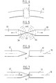
- FIG. 1 We see in Figures 1 and 2 attached a holding fiber polarization 10 having a cleaved end surface 12, planar and perpendicular to its longitudinal axis 14.
- Polarization maintaining fibers are well known from one skilled in the art. One will find for example a description of these fibers, including understood of their processes of obtaining and their properties in the document J. Noda, K. Okamoto and Y. Sasaki: "Polarization-Maintaining Fibers and their Applications ", Journal of Lightwave Technology, Vol.17.4, N ° 8, August 1986. For this reason the structure of these fibers to maintain polarization will not be described later.
- these fibers which maintain polarization can be of different types, one of the main of which concerns fibers having a generally elliptical cross-sectional core.
- the polarization-maintaining fiber 10 is firstly cleaved, as seen in Figure 4, to obtain an end face 12 perpendicular to its axis 14.
- the optical fiber cleavage step 10 consists in cutting said fiber so that its resulting end face 12 is at least substantially flat and orthogonal to its central axis.
- This cleavage step can be carried out according to any process of sectioning known to those skilled in the art, if necessary, by simple curvature of the fiber 10 until abrupt rupture of the latter after initiation breaking with a very hard edge, as shown on Figure 4.
- the procedure is preferably as follows.
- a small section of another fiber 30 is stretched (tension T) coaxially and symmetrically up to the rupture at a point 32, under the action of an electric arc.
- the drawn fiber 30 advantageously has a temperature of fusion equal to or close to that of the zone of the fiber to be lensed. he can for example, a multimode fiber with an index gradient, or even a single-mode fiber, although the latter has a temperature of superior fusion.
- the fiber section 30 may for example have a length of around ten cm. At the end of the stretching step, we thus obtain two ends of optical fiber 30 each having a tapered end in cone 34.
- a stretched end of optical fiber 30 is then placed opposite the cleaved end 12 of the fiber 10 and aligned with it, as shown in FIG. 6.
- This alignment can be carried out by any appropriate means, for example by placing the cleaved fiber 10 and the stretched fiber end 30, on suitable V-shaped supports.
- V-shaped sapphire supports commonly use such V-shaped sapphire supports, with an accuracy of the order of ⁇ m. For this reason, these supports in V are not shown in the appended figures and will not be described in more detail later.
- the tip of the drawn fiber 30 is then brought into contact mechanical with the cleaved face 12 of the fiber 10, and this under a slight axial pressure P, as shown in FIG. 7, while keeping the anterior alignment between the drawn fiber 30 and the cleaved fiber 10.
- the assembly obtained is subjected to an electric arc, as shown in Figure 8, to achieve fast and low fusion intensity of the tip of the drawn fiber 30.
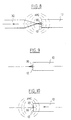
- This fiber 30 is removed as soon as the appearance of the welding of this point on the cleaved fiber 10. This removal of the drawn fiber 30 leads to release a glass needle 36 centered and linked at the heart of the cleaved fiber 10, as shown in FIG. 9.
- the removal of the stretched fiber 30 to form the needle 36 and the subsequent melting thereof are checked for obtain a lens 20 which has a hyperboloid profile around the axis 14 of the fiber 10 as seen in FIGS. 1 and 2.
- the controlled asphericity thus obtained is adapted to limit the aberrations and optimize the coupling.
- the method described above makes it possible to obtain a lens 20 of elliptical cross section, considered transversely to the axis 14 of fiber 10, as seen in FIG. 3.
- This elliptical cross section is obtained automatically thanks to the use of the elliptical environment of the fiber core 10 to polarization maintenance as a basis for hooking the lens 20 in manufacturing.
- the inventors have found experimentally that it is very difficult to obtain an elliptical cross-section lens by controlled supply of glass on the cleaved surface of a standard fiber. Indeed the forces of surface tension of the molten glass minimize the surface of the lens whose shape naturally approaches a sphere. And he is very difficult, if not impossible, without mechanical or chemical machining, modify the circular section of a lens thus deposited on a fiber standard.
- the lens 20 in profile in hyberboloid and of elliptical cross section therefore allows optimum coupling with the elliptical mode of phototransducers and also allows to convert this elliptical mode in a circular fashion.
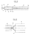
- a phototransducer 40 placed in look at the lens 20. Furthermore in FIG. 11 we can see a section 50 of multimode fiber with index gradient inserted between the cleaved end 62 of a single mode optical fiber 60 in circular mode and the section 10 of polarization maintaining fiber.
- the phototransducer 40, the lens 20, the section of fiber 10 with polarization maintenance and section 50 of fiber multimode with index gradient are all centered on the longitudinal axis 64 single-mode fiber 60.
- the lens 20 is placed on the cleaved surface 12 of the polarization-maintaining fiber section 10.
- the opposite end 16 of this section of fiber 10, also cleaved is fixed to a surface end cleaved 52 of the multimode gradient fiber section 50 index.
- the opposite end 54 of this fiber section 50, also cleaved is attached to the cleaved end surface 62 of the fiber singlemode 60.
- the multimode fiber section with gradient index 50 is used not as a fiber but as a gradient index lens.
- a multimode fiber element with an index gradient 50 provides angular torques input / output in perfect match.
- the length of the fiber element multimode gradient index optics 50 provides a beam any output conic selected.
- the "pitch" represents the period of the multimode gradient fiber index.
- the value of the pitch is mainly determined by the profile of the index gradient.
- the periodic aspect of the beam propagation inside the section 50 of multimode optical fiber makes it possible to increase the length of this fiber section 50 so as to facilitate the realization of the system.
- the opening cone of the beam may not coincide with the opening cone of the multimode gradient fiber index 50.
- This stretch of fiber multimode index-hopping optics acts as a material interlayer with the same index, between fiber 10 and section 50 of optical fiber multimode with index gradient.
- the multimode fiber section to index jump therefore increases the diameter of the incident beam up to the useful diameter of the multimode gradient 50 optical fiber index. It also provides the system with a significant advantage in increasing the frontal distance between the phototransducer 40 and the microlens 20.
- the index jump can be used fiber section 10 with polarization maintenance as a glass element interlayer (which avoids additional manipulation).
- the use of the above compounds in accordance with this invention allows to perfectly adapt the divergent beam from a source 40 at the input of the single-mode fiber 60.
- the coupling is in effect optimized by the perfect match between the conditions of light propagation (beam opening) and eigen modes different fibers.
- the single mode fiber assembly 60, aperture converter digital formed by the fiber sections 50 and 10 / microlens 20 is preferably performed by splicing, advantageously choosing fibers 60, 50 and 10 of the same outside diameter, for example of 125 ⁇ m.
- a such splicing can be done using a conventional machine splicing such as for example the model sold under the reference BFS50 by the company BEALE INTERNATIONAL TECHNOLOGY.
- the cutting of the fiber elements 10, 50, 60, for its part, can be obtained with a precision cleaver available on the market, such as the FUJIKURA CT-07 cleaver.
- a single lens 20 on the cleaved face of the fiber section 10 to maintaining polarization, but to place on this cleaved face a multi-lens, i.e. a succession of coaxial, convex lenses, of radii of curvature increasing in approach of the fiber 10. All these lenses 20 have generally elliptical sections and define in combination a profile generally in hyperboloid.
- step a) of stretching a new section of optical fiber 30 the taper of the tip obtained by stretching must be controlled to be able to release, in step d), a needle of suitable size compatible with the desired radius of curvature for the new lens.
- the inventors have used in testing a BTT type microsealer. Such a microsealer generates an electric arc.
- a signal optical can be injected at the unused end of fiber 60.
- the signal optical is then conveyed by the core of the fiber 60, and the passage of the optical signal in the element placed opposite and being aligned allows to check the correct positioning of the components.
- Such an optical alignment control step can complete effectively mechanical alignment.
- the geometry of the lens 20 can be refined if necessary, after deposit on the cleaved end 12 of the fiber polarization maintaining 10, by machining, for example by machining mechanical or chemical attack.
Landscapes
- Physics & Mathematics (AREA)
- Engineering & Computer Science (AREA)
- Plasma & Fusion (AREA)
- General Physics & Mathematics (AREA)
- Optics & Photonics (AREA)
- Optical Couplings Of Light Guides (AREA)
- Optical Fibers, Optical Fiber Cores, And Optical Fiber Bundles (AREA)
Claims (19)
- Verfahren zum Koppeln einer optischen Faser (60), die eine Mode mit kreisförmiger Feldverteilung aufweist, mit einem Lichtwandler (40), der eine Mode mit einer Feldverteilung elliptischer Art aufweist, welches die Schritte umfaßt, die darin bestehen, daß eine Nadel (36) aus dem Material der optischen Faser an einer ersten abgetrennten Endfläche (12) eines Faserstückes (10) mit konstanter Polarisation ausgebildet wird, das einen Kern aufweist, dessen Querschnitt elliptisch ist und dessen Schmelztemperatur unter der des Mantels des Faserstückes (10) mit konstanter Polarisation liegt, und die Nadel (36) unter Erwärmung so geformt wird, daß sich eine Linse (20) mit elliptischem Querschnitt und Hyperboloidprofil ergibt, deren Grundfläche im wesentlichen dem elliptischen Querschnitt des Kerns des Faserstückes (10) mit konstanter Polarisation zusammenfällt, und dann die zweite abgetrennte Endfläche (16) des Faserstückes (10) mit konstanter Polarisation einer abgetrennten Endfläche (62) der besagten Faser mit einer Mode mit kreisförmiger Feldverteilung gegenüberstehend angeordnet wird.
- Verfahren nach Anspruch 1 bei dem der Schritt der Ausbildung der Nadel aus dem Fasermaterial zum Formen der Linse (20) mit elliptischem Querschnitt und Hyperboloidprofil darin besteht, daßdas optische Faserstück mit konstanter Polarisation abgetrennt wird,koaxial unter Einwirkung einer Erwärmung ein Stück einer anderen Faser (30) bis zum Bruch gezogen wird, derart, daß zwei Halbteilstücke gebildet werden, von denen jedes ein Ende (34) in Form von einer Spitze hat,eines der beiden gezogenen Halbteilstücke der Faser (30) zum abgetrennten Ende (12) des optischen Faserstückes mit konstanter Polarisation (10) ausgerichtet wird und die Spitze (34) des besagten gezogenen Halbteilstücks (30) der Faser und der Kern des abgetrennten Endes (12) des optischen Faserstückes (10) mit konstanter Polarisation in mechanischen Kontakt gebracht werden undan den Kern des abgetrennten Endes (12) des optischen Faserstückes (10) mit konstanter Polarisation ein Teil der Spitze (34) des gezogenen Halbteilstückes (30) der Faser geschweißt wird, indem der Rest entfernt wird, derart, daß letztendlich nur die gewünschte Nadel (36) ausgebildet ist.
- Verfahren nach Anspruch 1 oder 2, welches den weiteren Schritt umfaßt, der darin besteht, daß das optische Faserstück (10) mit konstanter Polarisation direkt an der besagten zu koppelnden Faser (60) oder an einem optischen Faserstück (50) anderer Art befestigt wird.
- Verfahren nach Anspruch 3, bei dem die besagte zu koppelnde optische Faser (60) eine Einmodenfaser ist.
- Verfahren nach Anspruch 3, bei dem das optische Faserstück (50) anderer Art ein Mehrmoden-Faserstück mit Indexgradient ist.
- Verfahren nach Anspruch 3, bei dem das optische Faserstück (50) anderer Art ein Mehrmoden-Faserstück mit Indexstufe ist.
- Verfahren nach einem der Ansprüche 1 bis 6 in Kombination mit Anspruch 2, bei dem das gezogene Faserstück (30) ein Mehrmoden-Faserstück mit Indexgradient ist.
- Verfahren nach einem der Ansprüche 1 bis 7 in Kombination mit Anspruch 2, bei dem der genannte Schritt des Schweißens ineinem schnellen Aufschmelzen in geringer Stärke der Spitze (34) des gezogenen Faserhalbteilstücks (30) bei Schrumpfen der Halbteilstücke seit der Verschweißung der Spitze (34) am Kern der Faser (10) mit konstanter Polarisation (10) derart, daß nur die Nadel (36) bleibt, die an den Kern geschweißt ist, besteht, und daß der vorgenannte Schritt der Formung der Glasnadel (36) in einer Aufschmelzung dieser Nadel mit Hilfe wenigstens eines Durchlaufs unter Erwärmung in geringer Stärke besteht, bis die gewünschte Krümmung für die Linse (20) erhalten ist.
- Optisches System, das durch die Durchführung des Verfahrens nach einem der Ansprüche 1 bis 8 erhalten wird, mit einer Linse (20) in Form eines Hyperboloiden und mit elliptischem Querschnitt, die an einer ersten abgetrennten Endfläche (12) eines Faserstückes (10) mit konstanter Polarisation befestigt ist, das einen Kern aufweist, dessen Querschnitt elliptisch ist und dessen Schmelztemperatur unter der des Mantels des Faserstückes mit konstanter Polarisation liegt, wobei die Grundfläche der besagten Linse (20) im wesentlichen mit dem elliptischen Querschnitt des Kerns des Faserstückes (10) mit konstanter Polarisation zusammenfällt und die zweite abgetrennte Endfläche (16) des Faserstückes (10) mit konstanter Polarisation einer abgetrennten Endfläche (62) der optischen Hauptfaser (60) mit einer Mode mit kreisförmiger Feldverteilung gegenüberstehend angeordnet ist, die dazu bestimmt ist, mit einem Lichtwandler (40) gekoppelt zu werden, der eine Mode mit elliptischer Feldverteilung aufweist und der Linse gegenüberstehend angeordnet ist.
- System nach Anspruch 9, bei dem das optische Faserstück (10) mit konstanter Polarisation und somit die Linse direkt an der zu koppelnden Faser (60) oder an einem optischen Faserstück (50) anderer Art befestigt ist.
- System nach Anspruch 10, bei dem die zu koppelnde optische Faser (60) eine Einmoden-Faser ist.
- System nach Anspruch 10, bei dem das optische Faserstück (50) anderer Art ein Mehrmoden-Faserstück mit Indexgradient ist.
- System nach Anspruch 10, bei dem das optische Faserstück (50) anderer Art ein Mehrmoden-Faserstück mit Indexstufe ist.
- System nach einem der Ansprüche 9 oder 12, welches zwischen der optischen Hauptfaser (60), die zu koppeln ist, und dem Lichtwandler (40) eine Anordnung aufweist, die nacheinander aus einem Mehrmoden-Faserstück (50) mit Indexgradient, dem Faserstück (10) mit konstanter Polarisation und der Mikrolinse (20) aufgebaut ist.
- System nach einem der Ansprüche 9 bis 14, bei dem die Mikrolinse (20) aus einer Mehrfachlinse (20) mit einem Krümmungsradius besteht, der mit zunehmender Entfernung vom Lichtwandler (40) zunimmt.
- System nach einem der Ansprüche 9 bis 15, bei dem die verschiedenen Bauelemente (20, 10, 50) zwischen dem Lichtwandler (10) und der zu koppelnden Hauptfaser (60) durch Spleißen befestigt sind.
- System nach einem der Ansprüche 12 oder 14, bei dem das Mehrmoden-Faserstück (50) mit Indexgradient so ausgebildet ist, daß es das Bündel an die passende Mode der zu koppelnden optischen Faser (60) anpasst.
- System nach Anspruch 13, bei dem das Mehrmoden-Faserstück mit Indexsprung so ausgebildet ist, daß es den Durchmesser des Lichtbündels an den Nutzdurchmesser eines Mehrmoden-Faserstücks (50) mit Indexgradienten anpasst.
- System nach einem der Ansprüche 12, 14 oder 17, bei dem die Länge des optischen Mehrmoden-Faserstückes (50) mit Indexgradient in der Größenordnung von [n + 1] Faserperiode/2 mit (n = 0, 1, 2....) liegt.
Applications Claiming Priority (2)
| Application Number | Priority Date | Filing Date | Title |
|---|---|---|---|
| FR9404368 | 1994-04-13 | ||
| FR9404368A FR2718854B1 (fr) | 1994-04-13 | 1994-04-13 | Procédé de préparation d'une fibre optique en vue d'un couplage avec un phototransducteur et système optique ainsi obtenu. |
Publications (2)
| Publication Number | Publication Date |
|---|---|
| EP0677758A1 EP0677758A1 (de) | 1995-10-18 |
| EP0677758B1 true EP0677758B1 (de) | 2002-01-02 |
Family
ID=9462042
Family Applications (1)
| Application Number | Title | Priority Date | Filing Date |
|---|---|---|---|
| EP95400812A Expired - Lifetime EP0677758B1 (de) | 1994-04-13 | 1995-04-11 | Optische Anordnung zum Koppeln einer optischen Faser mit einem kreisförmigen Modenfeld und eines optoelektronischen Wandlers mit einem elliptischen Modenfeld sowie deren Herstellungsverfahren |
Country Status (4)
| Country | Link |
|---|---|
| US (1) | US5638471A (de) |
| EP (1) | EP0677758B1 (de) |
| DE (1) | DE69524801T2 (de) |
| FR (1) | FR2718854B1 (de) |
Families Citing this family (15)
| Publication number | Priority date | Publication date | Assignee | Title |
|---|---|---|---|---|
| US6415087B1 (en) | 1997-06-04 | 2002-07-02 | Corning Laserton, Inc. | Polished fused optical fiber endface |
| US6137938A (en) * | 1997-06-04 | 2000-10-24 | Lasertron, Inc. | Flat top, double-angled, wedge-shaped fiber endface |
| JP2000206359A (ja) * | 1999-01-18 | 2000-07-28 | Alps Electric Co Ltd | 光ファイバ結合装置 |
| US6148514A (en) * | 1999-04-02 | 2000-11-21 | Beaufrand; Emmanuel Marie Eugene | Method for butt-end electromechanical splicing |
| US6533467B2 (en) | 2001-01-11 | 2003-03-18 | Telect, Inc. | Optical fiber ferrule apparatus and method |
| AU2002323522A1 (en) * | 2001-08-29 | 2003-03-18 | 3M Innovative Properties Company | Optical devices using shaped optical fibers and methods for making optical devices with shaped optical fibers |
| US20030074924A1 (en) * | 2001-10-19 | 2003-04-24 | Melville Charles David | Method and apparatus for forming a lens on an optical fiber |
| US6904197B2 (en) * | 2002-03-04 | 2005-06-07 | Corning Incorporated | Beam bending apparatus and method of manufacture |
| US20030165290A1 (en) * | 2002-03-04 | 2003-09-04 | Bhagavatula Venkata A. | Optical signal altering lensed apparatus and method of manufacture |
| US6963682B2 (en) * | 2002-03-04 | 2005-11-08 | Corning Incorporated | Beam altering fiber lens device and method of manufacture |
| US7062135B2 (en) * | 2002-03-21 | 2006-06-13 | Corning Incorporated | Method for fabricating curved elements |
| CN100360967C (zh) * | 2002-12-31 | 2008-01-09 | 康宁股份有限公司 | 光纤透镜及制造方法 |
| US7099535B2 (en) * | 2002-12-31 | 2006-08-29 | Corning Incorporated | Small mode-field fiber lens |
| KR20060087564A (ko) * | 2003-09-25 | 2006-08-02 | 코닝 인코포레이티드 | 다중모드 접속용 광섬유로 이루어진 섬유 렌즈 |
| FR3036050B1 (fr) * | 2015-05-13 | 2017-06-09 | Univ Strasbourg | Dispositif de traitement laser et station de travail comportant un tel dispositif |
Family Cites Families (16)
| Publication number | Priority date | Publication date | Assignee | Title |
|---|---|---|---|---|
| US3932184A (en) * | 1973-05-29 | 1976-01-13 | Bell Telephone Laboratories, Incorporated | Fabrication of microlenses |
| US3910677A (en) * | 1974-05-13 | 1975-10-07 | Bell Telephone Labor Inc | Hyperbolic type optical fiber lens coupler for coupling the fiber to an optical line source |
| US4143940A (en) * | 1975-05-09 | 1979-03-13 | U.S. Philips Corporation | Device for coupling a radiation source to a monomode optical transmission fiber with the aid of a resonant cavity |
| JPS575380A (en) * | 1980-06-11 | 1982-01-12 | Kokusai Denshin Denwa Co Ltd <Kdd> | Output light coupling system for semiconductor laser |
| JPS57150810A (en) * | 1981-03-13 | 1982-09-17 | Fujitsu Ltd | Connecting method of general fiber and low polarization fiber |
| JPS58158620A (ja) * | 1982-03-17 | 1983-09-20 | Hitachi Ltd | 光通信装置およびこれに用いる光フアイバならびに光フアイバの加工方法 |
| DE3486097D1 (de) * | 1984-03-02 | 1993-04-15 | Siemens Ag | Koppelanordnung zum ankoppeln eines lichtwellenleiters an einen halbleiterlaser und verfahren zur herstellung einer solchen anordnung. |
| US4818263A (en) * | 1987-06-11 | 1989-04-04 | Tektronix, Inc. | Method and apparatus for precisely positioning microlenses on optical fibers |
| US5011254A (en) * | 1989-11-30 | 1991-04-30 | At&T Bell Laboratories | Coupling of optical devices to optical fibers by means of microlenses |
| US5037174A (en) * | 1990-01-31 | 1991-08-06 | E. I. Du Pont De Nemours And Company | Optical fiber having an aspherical lens thereon and method of making same |
| JPH03252617A (ja) * | 1990-03-02 | 1991-11-11 | Fujitsu Ltd | 光ファイバ型偏波分離器 |
| US5216733A (en) * | 1991-03-11 | 1993-06-01 | Nippon Telegraph And Telephone Corporation | Polarization maintaining optical fiber connector including positioning flange and method utilizing same |
| FR2681437B1 (fr) * | 1991-09-18 | 1995-01-20 | France Telecom | Fibre optique perfectionnee pour couplage avec un phototransducteur et procede de preparation. |
| CA2098903C (en) * | 1992-06-24 | 1999-02-16 | Shigeru Hirai | Optical fiber functional device |
| FR2699293B1 (fr) * | 1992-12-15 | 1995-03-03 | France Telecom | Système optique monolithique comportant des moyens de couplage perfectionnés entre une fibre optique et un phototransducteur. |
| JP3282889B2 (ja) * | 1993-08-04 | 2002-05-20 | 古河電気工業株式会社 | レンズ付き光ファイバ |
-
1994
- 1994-04-13 FR FR9404368A patent/FR2718854B1/fr not_active Expired - Fee Related
-
1995
- 1995-04-11 DE DE69524801T patent/DE69524801T2/de not_active Expired - Fee Related
- 1995-04-11 EP EP95400812A patent/EP0677758B1/de not_active Expired - Lifetime
- 1995-04-12 US US08/420,853 patent/US5638471A/en not_active Expired - Lifetime
Non-Patent Citations (1)
| Title |
|---|
| Electronics Letters, Vol.18, No.17, 1992, pages 1654-1656 * |
Also Published As
| Publication number | Publication date |
|---|---|
| FR2718854B1 (fr) | 1996-07-12 |
| DE69524801D1 (de) | 2002-02-07 |
| DE69524801T2 (de) | 2002-08-14 |
| FR2718854A1 (fr) | 1995-10-20 |
| US5638471A (en) | 1997-06-10 |
| EP0677758A1 (de) | 1995-10-18 |
Similar Documents
| Publication | Publication Date | Title |
|---|---|---|
| EP0603042A1 (de) | Monolithisches System zur Kopplung zwischen einer optischen Faser und optoelektronischem Bauteil | |
| EP0677758B1 (de) | Optische Anordnung zum Koppeln einer optischen Faser mit einem kreisförmigen Modenfeld und eines optoelektronischen Wandlers mit einem elliptischen Modenfeld sowie deren Herstellungsverfahren | |
| EP0825464B1 (de) | Verfahren zur Herstellung und Montage von einem kollektiven optischen Kopplungselement am Ende eines Bündels von mehreren Monomodenfasern | |
| EP0121482B1 (de) | Wellenlängenmultiplexer/-demultiplexer und Verfahren zur Herstellung einer solchen Vorrichtung | |
| EP0061378B1 (de) | Verfahren zur überprüften Änderung der geometrischen Charakteristiken des äussersten Endes einer optischen Monomode-Faser und Anwendung zur optischen Koppelung | |
| KR100822953B1 (ko) | 광 도파관 렌즈 및 그 제조방법 | |
| EP1326105B1 (de) | Optische Koppler für multimode Pumpe | |
| EP0534819B1 (de) | Verfahren zur Begrenzung der Kupplungsverluste zwischen einer optischen Monomodefaser und einem optischen System mit einem niedrigeren Modenfleckdurchmesser oder zwischen zwei Monomodefasern mit gleichem Modenfleckdurchmesser | |
| EP1327171B1 (de) | Optischer kollimator für monomode-fasern und monomode-faser mit integriertem kollimator | |
| FR2699292A1 (fr) | Procédé de préparation par lentillage multiple d'une fibre optique en vue d'un couplage optimum avec un phototransducteur et système optique obtenu. | |
| EP0715192A1 (de) | Methode zur Kopplung einer optischen Mehrkernfaser mit mehreren optischen Fasern, die einen Kern enthalten | |
| FR2629219A1 (fr) | Coupleur de fibres optiques en etoile et de type actif | |
| FR2465238A1 (fr) | Dispositif de couplage entre une source lumineuse a rayonnement divergent et une fibre optique et procede de realisation d'un tel dispositif | |
| EP0718648A1 (de) | Herstellungsverfahren für optischen Mehrfachfaserverteiler und damit hergestellter optischer Verteiler | |
| FR2860599A1 (fr) | Dispositif de couplage optique d'une fibre monomode multi-coeurs, et procede de fabrication correspondant | |
| EP0286475B1 (de) | Verfahren zur Veränderung des Reflexionskoeffizienten eines Monomodefaserendes und mittels dieses Verfahrens hergestelltes Faserinterferometer | |
| EP0077259A1 (de) | Verfahren und Vorrichtung zum Messen des effektiven Diameters des Leitmodus in einer monomoden optischen Faser | |
| EP1502140A1 (de) | Optischer hülsen verbinder | |
| FR2818033A1 (fr) | Module a diode laser | |
| FR2695733A1 (fr) | Procédés de préparation du raccordement par épissurage d'un dispositif d'optique intégrée à au moins un câble optique. | |
| EP1151334B1 (de) | Dämpfungsglied für monomodefaser und zugehöriges herstellungsverfahren | |
| EP0725290A1 (de) | Multisteckerstift für Verbindung von Fasern, ihr verwendender Stecker und sein Herstellungsverfahren | |
| FR2681437A1 (fr) | Fibre optique perfectionnee pour couplage avec un phototransducteur et procede de preparation. | |
| FR2747799A1 (fr) | Procede de realisation d'un dispositif de couplage pour fibre optique | |
| EP0083278A2 (de) | Dämpfungsglied für die Verbindung mittels einer optischen Faser und Verbindungsstück mit einem solchen Glied |
Legal Events
| Date | Code | Title | Description |
|---|---|---|---|
| PUAI | Public reference made under article 153(3) epc to a published international application that has entered the european phase |
Free format text: ORIGINAL CODE: 0009012 |
|
| AK | Designated contracting states |
Kind code of ref document: A1 Designated state(s): DE GB |
|
| 17P | Request for examination filed |
Effective date: 19960318 |
|
| 17Q | First examination report despatched |
Effective date: 19990604 |
|
| RTI1 | Title (correction) |
Free format text: OPTICAL SYSTEM FOR COUPLING AN OPTICAL FIBRE WITH A CIRCULAR MODE AND A PHOTOTRANSDUCER WITH AN ELLIPTIC MODE AND ITS MANUFACTURING PROCESS |
|
| GRAG | Despatch of communication of intention to grant |
Free format text: ORIGINAL CODE: EPIDOS AGRA |
|
| GRAG | Despatch of communication of intention to grant |
Free format text: ORIGINAL CODE: EPIDOS AGRA |
|
| GRAH | Despatch of communication of intention to grant a patent |
Free format text: ORIGINAL CODE: EPIDOS IGRA |
|
| GRAH | Despatch of communication of intention to grant a patent |
Free format text: ORIGINAL CODE: EPIDOS IGRA |
|
| GRAA | (expected) grant |
Free format text: ORIGINAL CODE: 0009210 |
|
| REG | Reference to a national code |
Ref country code: GB Ref legal event code: IF02 |
|
| AK | Designated contracting states |
Kind code of ref document: B1 Designated state(s): DE GB |
|
| REF | Corresponds to: |
Ref document number: 69524801 Country of ref document: DE Date of ref document: 20020207 |
|
| RAP2 | Party data changed (patent owner data changed or rights of a patent transferred) |
Owner name: ALCATEL |
|
| GBT | Gb: translation of ep patent filed (gb section 77(6)(a)/1977) |
Effective date: 20020507 |
|
| PLBE | No opposition filed within time limit |
Free format text: ORIGINAL CODE: 0009261 |
|
| STAA | Information on the status of an ep patent application or granted ep patent |
Free format text: STATUS: NO OPPOSITION FILED WITHIN TIME LIMIT |
|
| 26N | No opposition filed | ||
| PGFP | Annual fee paid to national office [announced via postgrant information from national office to epo] |
Ref country code: GB Payment date: 20040414 Year of fee payment: 10 |
|
| PGFP | Annual fee paid to national office [announced via postgrant information from national office to epo] |
Ref country code: DE Payment date: 20040415 Year of fee payment: 10 |
|
| PG25 | Lapsed in a contracting state [announced via postgrant information from national office to epo] |
Ref country code: GB Free format text: LAPSE BECAUSE OF NON-PAYMENT OF DUE FEES Effective date: 20050411 |
|
| PG25 | Lapsed in a contracting state [announced via postgrant information from national office to epo] |
Ref country code: DE Free format text: LAPSE BECAUSE OF NON-PAYMENT OF DUE FEES Effective date: 20051101 |
|
| GBPC | Gb: european patent ceased through non-payment of renewal fee |
Effective date: 20050411 |