EP0677404B1 - Antriebsachse für Höheneinstellung der Antriebsräder einer selbstangetriebenen Maschine mit demontierbaren Lagern und Maschine mit solcher Achse - Google Patents
Antriebsachse für Höheneinstellung der Antriebsräder einer selbstangetriebenen Maschine mit demontierbaren Lagern und Maschine mit solcher Achse Download PDFInfo
- Publication number
- EP0677404B1 EP0677404B1 EP95200863A EP95200863A EP0677404B1 EP 0677404 B1 EP0677404 B1 EP 0677404B1 EP 95200863 A EP95200863 A EP 95200863A EP 95200863 A EP95200863 A EP 95200863A EP 0677404 B1 EP0677404 B1 EP 0677404B1
- Authority
- EP
- European Patent Office
- Prior art keywords
- bearing
- side plate
- aperture
- axle
- axle according
- Prior art date
- Legal status (The legal status is an assumption and is not a legal conclusion. Google has not performed a legal analysis and makes no representation as to the accuracy of the status listed.)
- Expired - Lifetime
Links
- 230000000295 complement effect Effects 0.000 claims description 8
- 239000004519 grease Substances 0.000 claims description 7
- 229920002994 synthetic fiber Polymers 0.000 claims description 5
- 230000000903 blocking effect Effects 0.000 claims description 3
- 235000015250 liver sausages Nutrition 0.000 claims 1
- 230000002787 reinforcement Effects 0.000 claims 1
- 238000005096 rolling process Methods 0.000 description 7
- 229910000906 Bronze Inorganic materials 0.000 description 3
- 239000010974 bronze Substances 0.000 description 3
- 239000004020 conductor Substances 0.000 description 3
- KUNSUQLRTQLHQQ-UHFFFAOYSA-N copper tin Chemical compound [Cu].[Sn] KUNSUQLRTQLHQQ-UHFFFAOYSA-N 0.000 description 3
- 239000002184 metal Substances 0.000 description 3
- 238000000605 extraction Methods 0.000 description 2
- 238000005304 joining Methods 0.000 description 2
- 238000004519 manufacturing process Methods 0.000 description 2
- 239000000463 material Substances 0.000 description 2
- 230000002093 peripheral effect Effects 0.000 description 2
- 239000004809 Teflon Substances 0.000 description 1
- 229920006362 Teflon® Polymers 0.000 description 1
- 239000003831 antifriction material Substances 0.000 description 1
- 238000005452 bending Methods 0.000 description 1
- 230000015556 catabolic process Effects 0.000 description 1
- 239000011248 coating agent Substances 0.000 description 1
- 238000000576 coating method Methods 0.000 description 1
- 230000000052 comparative effect Effects 0.000 description 1
- 238000005520 cutting process Methods 0.000 description 1
- 230000003247 decreasing effect Effects 0.000 description 1
- 230000002950 deficient Effects 0.000 description 1
- 238000006731 degradation reaction Methods 0.000 description 1
- 230000009977 dual effect Effects 0.000 description 1
- 238000002347 injection Methods 0.000 description 1
- 239000007924 injection Substances 0.000 description 1
- 229910001092 metal group alloy Inorganic materials 0.000 description 1
- 238000000034 method Methods 0.000 description 1
- 239000002991 molded plastic Substances 0.000 description 1
- 230000035939 shock Effects 0.000 description 1
Images
Classifications
-
- B—PERFORMING OPERATIONS; TRANSPORTING
- B60—VEHICLES IN GENERAL
- B60B—VEHICLE WHEELS; CASTORS; AXLES FOR WHEELS OR CASTORS; INCREASING WHEEL ADHESION
- B60B35/00—Axle units; Parts thereof ; Arrangements for lubrication of axles
- B60B35/12—Torque-transmitting axles
- B60B35/18—Arrangement of bearings
-
- F—MECHANICAL ENGINEERING; LIGHTING; HEATING; WEAPONS; BLASTING
- F16—ENGINEERING ELEMENTS AND UNITS; GENERAL MEASURES FOR PRODUCING AND MAINTAINING EFFECTIVE FUNCTIONING OF MACHINES OR INSTALLATIONS; THERMAL INSULATION IN GENERAL
- F16C—SHAFTS; FLEXIBLE SHAFTS; ELEMENTS OR CRANKSHAFT MECHANISMS; ROTARY BODIES OTHER THAN GEARING ELEMENTS; BEARINGS
- F16C17/00—Sliding-contact bearings for exclusively rotary movement
- F16C17/02—Sliding-contact bearings for exclusively rotary movement for radial load only
-
- F—MECHANICAL ENGINEERING; LIGHTING; HEATING; WEAPONS; BLASTING
- F16—ENGINEERING ELEMENTS AND UNITS; GENERAL MEASURES FOR PRODUCING AND MAINTAINING EFFECTIVE FUNCTIONING OF MACHINES OR INSTALLATIONS; THERMAL INSULATION IN GENERAL
- F16C—SHAFTS; FLEXIBLE SHAFTS; ELEMENTS OR CRANKSHAFT MECHANISMS; ROTARY BODIES OTHER THAN GEARING ELEMENTS; BEARINGS
- F16C33/00—Parts of bearings; Special methods for making bearings or parts thereof
- F16C33/02—Parts of sliding-contact bearings
- F16C33/04—Brasses; Bushes; Linings
- F16C33/20—Sliding surface consisting mainly of plastics
-
- F—MECHANICAL ENGINEERING; LIGHTING; HEATING; WEAPONS; BLASTING
- F16—ENGINEERING ELEMENTS AND UNITS; GENERAL MEASURES FOR PRODUCING AND MAINTAINING EFFECTIVE FUNCTIONING OF MACHINES OR INSTALLATIONS; THERMAL INSULATION IN GENERAL
- F16C—SHAFTS; FLEXIBLE SHAFTS; ELEMENTS OR CRANKSHAFT MECHANISMS; ROTARY BODIES OTHER THAN GEARING ELEMENTS; BEARINGS
- F16C2310/00—Agricultural machines
Definitions
- the invention relates to an axle for driving and adjusting the height of the drive wheels of a self-propelled rolling machine with a walking conductor, that is to say of the type held and guided by hand by the user walking in maneuvering.
- a walking conductor that is to say of the type held and guided by hand by the user walking in maneuvering.
- self-propelled rolling machines we can mention lawn mowers, mowers, brushcutters ...
- These self-propelled machines generally comprise a driving axle comprising a driving shaft driven in rotation and carrying two driving wheels.
- the drive wheels are also adjustable in height relative to the machine housing to allow adjustment of a cutting height.
- a bearing is carried by a side wall of the casing of the machine, and this bearing is crossed by the motor shaft which it supports.
- a wheel support flange is carried by the bearing outside the casing. This flange carries the axis of rotation of the wheel.
- the free end of the motor shaft extending out of the bearing is coupled in rotation to a drive pinion which engages in a toothed ring secured to the wheel to drive it in rotation.
- An operating handle mounted integral with the support flange makes it possible to adjust its position relative to the casing wall by rotating it around the axis of the motor shaft.
- the axis of rotation of the wheel being off-center with respect to the axis of the motor shaft, the height position of the wheel relative to the casing is thus modified.
- the bearing which supports the motor shaft and the flange generally consists of a low-cut metal part welded to the flange, and supporting a ball bearing for guiding the motor shaft.
- each wheel drive end pinion is mounted on the drive shaft by means of a particularly fragile free wheel.
- this freewheel deteriorates, it generates a masting of the motor shaft, which requires the change of the motor shaft.
- the change of the drive shaft can only be done by changing the entire axle, namely the drive shaft, the two bearings with their ball bearings, and the two support flanges generally connected by a connecting bar parallel to the motor shaft for a common control of the height adjustment.
- the bearings of known machines formed of turned parts incorporating a ball bearing, have a relatively high cost price compared to the cost of the other components of such a machine intended for the general public.
- US-A-4,785,612 describes a mower whose motor shaft is rotatably mounted relative to the wheel support by means of a first fixed bearing interposed between the shaft and an external tube to which the support is fixed.
- the outer tube is mounted relative to the casing thanks to a second fixed bearing allowing the adjustment of the wheels in height.
- This assembly is complex, expensive and cannot be dismantled.
- the invention aims to overcome these drawbacks by proposing an axle for driving and adjusting the height of the driving wheels of a self-propelled rolling machine with a walking driver, in which the motor shaft and its bearings can be easily removed from the axle by view of their replacement.
- the invention also aims to provide a such an axle, the cost price of which is lower than that of known axles, the bearings of which consist of turned parts with ball bearings.
- the invention also aims to propose such an axle which has satisfactory mechanical characteristics, in particular in terms of reliability, durability, rigidity.
- the invention aims to propose such an axle, the bearings of which do not include ball bearings but which nevertheless have an equivalent longevity and resistance.
- the invention relates to an axle for driving and adjusting the height of the driving wheels of a self-propelled rolling machine with a walking conductor, such as a lawn mower, comprising a motor shaft driven in rotation and, for the mounting of each drive wheel, a bearing carried by a side wall of the machine casing and traversed by the drive shaft which it supports, a wheel support flange carried by the bearing and carrying an axle on which the wheel is freely rotatably mounted, the free end of the motor shaft extending out of the bearing to be rotatably coupled to a wheel drive pinion, characterized in that the support flange has a through lumen to receive the bearing , in that the cross section of the bearing in its portion extending between the lumen of the support flange and its free end engaged inside the wall of the housing has overall dimensions perpendicular cularily to the axis of the bearing which are less than or equal to those of the cross section of the lumen of the support flange and in that the support flange is mounted on the bearing by means
- the invention further relates to an axle for driving and adjusting the height of the drive wheels of a self-propelled rolling machine with a walking conductor, such as a lawn mower, comprising a motor shaft driven in rotation, and for mounting each driving wheel, a bearing for guiding the motor shaft.
- the guide bearing is in the general form of a sleeve mounted fixed relative to a wall of the casing and defines an internal generally cylindrical bearing surface for guiding revolution and for supporting the rotary motor shaft which passes through the bearing, and an outer cylindrical bearing surface for guiding and supporting a support flange for the drive wheel which is thus carried by the bearing.
- the bearing according to the invention therefore has a dual function of guiding and rotating support, on the one hand of the motor shaft, on the other hand of the support flange.
- the bearing according to the invention forms an axial locking stop of the motor shaft preventing the axial sliding of the motor shaft towards the inside of the casing of the machine. It therefore also has a third locking function in axial translation of the motor shaft.
- the bearing is a plain bearing and therefore does not include a ball bearing.
- the bearing is formed by two half-bearings joining by an axial joint plane and the two half-bearings are associated with each other around the motor shaft by at least one stud fixed to the 'a half bearing engaged in a recess complementary to the other half bearing.
- the two half-bearings are identical and comprise on one side of the axis a series of pins and on the other side of the axis a series of complementary recesses.
- the bearing comprises grease traps consisting of recesses formed in its internal surface in contact with the motor shaft.
- a bearing according to the invention is therefore self-lubricated.
- this bearing can be made of a hard and rigid synthetic material, in particular ABS or, if necessary, bronze or equivalent material.
- the means of association of the bearing on the flange are adapted to allow the mounting and dismounting of the bearing in the workshop in a simple and rapid manner.
- the light passing through the support flange is a light stamped axially through the support flange towards the inside of the casing.
- the external surface of the bearing defines a bearing introduced into this light which is also cylindrical, the radial dimensions of the light being similar to those of the bearing to allow guiding in rotation of the support flange relative to the bearing allowing the adjustment in wheel height.
- the invention further relates to a self-propelled rolling machine with a walking driver - in particular a lawn mower - comprising at least one axle according to the invention.
- the invention also relates to an axle comprising in combination all or part of the characteristics mentioned above or below.
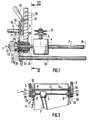
- the axle 1 motor for driving and adjusting the height of the drive wheels 2 of a self-propelled rolling machine comprises a drive shaft 3 driven in rotation and coupled to the drive wheels 2.
- the drive shaft 3 is driven by a reduction gear 4 carried by the motor shaft 3 which constitutes the output shaft of this reduction gear 4.
- the reduction gear 4 receives the motor movement on its input shaft 5 by a pulley 6 receiving a belt 7 also connected to a powertrain (not shown) generally consisting of a thermal or electric motor of the machine.
- the axle 1 For the mounting of each driving wheel 2, and of the driving shaft 3 on each side of the casing, the axle 1 comprises a bearing 8 carried by a side wall 9 vertical of the casing of the machine.
- the bearing 8 is crossed by the drive shaft 3 and supports this drive shaft 3 relative to the wall 9 of the housing.
- the axle 1 also includes a flange 10 for supporting the wheel 2.
- This flange 10 is carried by the bearing 8 on the outside and facing the side wall 9 of the casing, and itself carries a horizontal axis 11 s 'extending outwards and on which the wheel 2 is mounted freely rotatable.
- the free end 12 of the motor shaft 3 which extends outside of the bearing 8 is coupled in rotation to a pinion 13 for driving the wheel 2.
- This pinion 13 is advantageously mounted on the motor shaft 3 by l 'through a unidirectional link device such as a freewheel.
- the pinion 13 with external teeth cooperates with a crown secured to the wheel 2 in a manner known per se.
- the axle 1 comprises a rigid horizontal connecting bar 14, parallel to the drive shaft 3 and connecting the two flanges 10 for supporting the two wheels 2.
- the two wheels 2 of the same axle 1 can be adjusted in height with respect to the casing by means of a single height adjustment operating device 15, carried by one of the flanges 10.
- This device 15 consists of an elastic bar in bending fixed at one of its ends to the flange 10 by a bolt 16, and carrying a projection 17 adapted to be introduced into one of the recesses 18 formed in the side wall 9. According to the recess 18 in which the projection 17 is placed by acting on the bar 15, the position of the flange 10 in rotation relative to the wall 9 can be modified.
- the axis 11 of rotation of the wheel 2 being off-center with respect to the axis 19 of the motor shaft 3, around which the flange 10 can rotate, the height of the wheel 2 is modified relative to the casing of the machine thanks to to the bar 15.
- the connecting bar 14 ensures that the two flanges 10 rotate in parallel, so that the bar 15 makes it possible to simultaneously adjust the height of the two wheels 2 of the same axle.
- the flange 10 has a through hole 27 for receiving the bearing 8.
- the flange 10 is mounted on the bearing 8 by means of association adapted to allow its subsequent disassembly.
- the bearing 8 is not welded to the flange 10.
- the flange 10 is therefore mounted on the bearing 8 by means allowing the mounting and dismounting of the bearing 8 in the workshop.
- the cross section of the bearing 8 in its portion extending between the lumen 27 of the support flange 10 and the free end 33 of the bearing 8 extending inside the wall 5 of the housing a overall dimensions perpendicular to the axis 19 of the bearing which are less than or equal to those of the cross section of the lumen 27 of the support flange 10.
- this bearing 8 can be mounted by introducing it from the outside of the casing through the flange 10 and the wall 9 of the casing, or disassembled from the outside of the casing by axial extraction from the wall 9 of the casing and the flange 10.
- the overall dimensions of the bearing 8 perpendicular to its axis 19 are constant along the portion of the bearing 8 introduced through the flange 10 and the wall 9 of the casing.
- the bearing 8 consists of a barrel 20 introduced through the flange 10 and the wall 9 of the casing and forming an external bearing 21 which can be clamped in a recess 22 of complementary shape formed in notch in the wall 9 of the casing.
- the external bearing surface 21 of the bearing 8 is maintained and clamped in this recess 22 by means of a plate 23 closing the recess 22 and fixed under the wall 9 of the casing by means of two screws 24 engaged in blind threads 25 with vertical axis of the wall 9.
- the plate 23 is clamped against the outer surface 21 of the bearing 8 so as to maintain this bearing 8 without play in the recess 22 of the wall 9, and to block the bearing 8 in rotation relative to the wall 9.
- the external bearing 21 of the bearing 8 is cylindrical of revolution and the recess 22 is in the form of a semi-cylindrical notch allowing the mounting and disassembly of the bearing 8 in and out of this recess 22 when the plate 23 is removed.
- the bearing surface 21 of the bearing 8 and the recess 22 could not be cylindrical and be of polygonal and / or grooved cross section in order to improve the rotation blocking of the bearing 8 relative to the wall 9.
- the barrel 20 of the bearing 8 furthermore defines a bearing surface 26, cylindrical of revolution around the axis 19, and which is engaged in the through hole 27 cylindrical cylindrical of revolution of the flange 10.
- this bearing surface 26 is a cylindrical bearing surface of the external surface of the barrel 20 which is of the same diameter and in extension of the external cylindrical bearing surface 21 engaged in the recess 22 of the wall 9.
- the barrel 20 has a continuously cylindrical external surface of revolution between the light 27 of the flange 10 and the free end 33 of the bearing 8.
- the overall dimensions of the bearing 8 are therefore constant between the light 27 of the flange 10 and the free end 33 of the bearing 8.
- the bearing 26 supporting the flange 10 and the opening 27 of the flange 10 could be of a diameter greater than the bearing surface 21 engaged in the recess 22 of the wall 9 of the casing. The overall dimensions of the bearing 8 would then be decreasing between the bearing 26 and the free end 33.
- the cylindrical through lumen 27 is stamped axially through the flange 10 towards the inside of the casing to receive the bearing 8.
- the lumen 27 consists of the central recess of a cylindrical skirt 28 obtained by stamping in and through the flange 10 and extending axially towards the inside of the casing, that is to say towards the wall 9.
- This skirt 28 has its internal cylindrical surface of revolution which comes into contact with the cylindrical surface 26 of the bearing 8 for guide it in rotation.
- the bearing 26 of the bearing 8 is introduced into the lumen 27, the radial dimensions of this lumen 27 being similar to those of the bearing 26 to allow guiding in rotation of the flange 10 relative to the bearing 8.
- the skirt 28 forming the light 27 (and therefore the flange 10) is suitable for journalling around the external cylindrical surface 26 of the bearing 8 when the device 15 for unlocking is unlocked.
- the flange 10 is rotated around the bearing 8, which allows the height adjustment of the wheels 2.
- the cylindrical internal surface of the skirt 28 plays the role of a plain bearing guiding the rotation of the flange 10 around the bearing 8.
- this rotary mounting of the flange 10 relative to the bearing 8 allows the mounting and dismounting in the workshop of the bearing 8 relative to the flange 10.
- the bearing 8 is made of synthetic material and the support flange 10 is made of a metal alloy.
- the cylindrical surface 26 of the bearing 8 may have a diameter slightly greater than the internal diameter of the lumen 27.
- the bearing 8 is then forcibly engaged in the lumen 27 with a certain elastic radial deformation. This deformation does not, however, block the skirt 28 (and the flange 10) in rotation around the bearing 8, so that the height of the wheels 2 remains possible.
- this bearing 8 made of synthetic material at least partially absorbs the shocks between the wheel 2 mounted on the flange 10 and the shaft 3.
- the bearing 8 therefore consists of this barrel 20, and an outer collar 29 abutting against the outer face 30 of the flange 10 in order to axially block the bearing 8 towards the inside of the casing relative to the flange 10 and to the wall 9 of the casing.
- a removable elastic ring 31 for axial locking is engaged in a peripheral groove 32 of the motor shaft 3, immediately outside the collar 29 of the bearing 8.
- This removable ring 31 or circlips comes into abutment against the collar 29 of the bearing 8 and therefore prevents the axial sliding of the shaft 3 towards the inside of the casing.
- the two locking rings 31 provided at each end of the shaft 3 and coming into abutment against each of the two bearings 8 for mounting each of the two driving wheels 2, carry out an axial locking in the two directions of the driving shaft 3 by relative to the flanges 10 and to the side walls 9 of the casing.
- the rings 31 could be replaced by other equivalent axial locking means such as pins or the like.
- the end 32 of the skirt 28 of the flange 10 facing inwards abuts against the external face of the wall 9.
- a washer can be provided between this end 32 and the external face of the wall 9.
- the free end 33 of the external surface of the barrel 20, opposite the collar 29, comprises a chamfer 34 facilitating the introduction of the barrel 20 through the lumen 27 of the flange 10. Furthermore, the free end 35 of the internal surface 36 of the bearing 8, opposite the collar 29, that is to say oriented towards the inside of the casing, also comprises a chamfer 37 facilitating the introduction of the end 12 of the motor shaft 3 into the level 8.
- the bearing 8 is a plain bearing without a ball bearing therefore defining a cylindrical internal surface 36 of revolution in contact with the motor shaft 3.
- the bearing 8 is in the general form of a sleeve and is mounted fixed relative to a wall 9 of the casing, and defines an internal surface 36 which is generally cylindrical, of revolution for guiding and supporting the rotary motor shaft 3, and a surface external 26 cylindrical revolution of guide and support for the flange 10 for supporting the corresponding drive wheel 2.
- the support flange 10 is therefore guided and carried by the bearing 8. The same applies to the motor shaft 3.
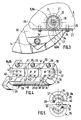
- the bearing 8 consists of a hard and rigid synthetic material - in particular ABS -, and is formed by two half-bearings 8a, 8b joining by a joint plane axial 38.
- Each half-bearing 8a, 8b is formed from a molded plastic part.
- the two half-bearings 8a, 8b are associated with each other around the drive shaft 3 by at least one stud 39 secured to a half-bearing 8a, 8b engaged in a complementary recess 40 of the other half-bearing 8b, 8a.
- Figure 4 shows a half-bearing 8a or 8b.
- the two half-bearings 8a, 8b are identical and comprise on one side of the axis 19 a series of pins 39 (three pins in the example shown) and, on the other side of the axis 19, a series complementary recesses 40 (three recesses in the example shown) coming opposite the studs 39 of the other half-bearing 8b, 8a.
- the pins 39 extend perpendicular to the joint plane 38 and have a shape and dimensions corresponding to those of the recesses 40 which are formed perpendicular to the joint plane 38.
- the pins 39 have an end head of larger diameter , tapered and forming a non-return shoulder.
- the recesses 40 may also include an internal non-return shoulder.
- the two half-bearings 8a, 8b being strictly identical, their manufacture is extremely inexpensive since it can be carried out for example by injection using a single mold.
- the bearing 8 further comprises grease traps 41, 42 consisting of recesses formed in its internal surface 36 in contact with the motor shaft 3.
- These grease traps include recesses in the form of a circular peripheral groove 41, and on the one hand and other of these circular recesses 41, blind holes 42 regularly distributed.
- Disassembly of the bearings 8 and of the motor shaft 3 is carried out by reversing these operations. Note, however, that only bearing 8 can be replaced if necessary. To do this, it suffices to dismantle the pinions 13 and the freewheel, to loosen the screws 24 tightening the plate 23 against the bearing 8, then to drive each defective bearing 8 outwards by extracting it from the light 27 of the flange 10 after having removed the corresponding circlip 31. For the mounting of a new bearing 8, these operations are carried out in the reverse direction.
- a bearing 8 according to the invention can also be made of metal, for example bronze or equivalent material.
- the internal surface 36 of the bearing 8 can be formed of a coating of anti-friction material such as bronze, Teflon or equivalent, in the manner of a pad.
- the bearing 8 is made of metal, it can be made in one piece or also in two half-bearings 8a, 8b in a similar manner to the example shown in Figure 4.
- the pins 39 are preferably cylindrical, as are the complementary recesses 40.
- the bearing 8 according to the invention does not include a ball bearing, comparative tests have shown that it has a perfectly satisfactory lifetime. To do this, an axle according to the invention was subjected to cycles of rotation under strong vibrations. And it has been found that the longevity of the bearings 8 is equivalent to that of the prior bearings with ball bearings. In practice, this result is explained by the fact that the efficiency of a ball bearing supposes an extremely precise assembly impossible to achieve in practice in machines of the prior art, taking into account the low tolerances required for the manufacture of the others. machine components, including the housing.
Landscapes
- Engineering & Computer Science (AREA)
- General Engineering & Computer Science (AREA)
- Mechanical Engineering (AREA)
- Harvester Elements (AREA)
Claims (12)
- Achse zum Antrieb und zur Höheneinstellung der Antriebsrädern (2) einer fahrbaren, durch eine gehende Person gesteuerten Maschine mit Eigenantrieb wie eines Rasenmähers, umfassend eine rotierend angetriebene Antriebswelle (3) und zur Anbringung jedes Antriebsrades (2) ein durch eine Seitenwand (9) des Maschinengehäuses abgestütztes Lager (8), wobei die Antriebswelle (3) durch das sie abstützende Lager (8) verläuft, eine Seitenplatte (10) zum Abstützen des Rades (2), die an dem Lager (8) angeordnet ist und eine Spindel (11) trägt, an der das Rad (2) frei drehbar angebracht ist, während sich das freie Ende (12) der Antriebswelle (3) zwecks rotierender Kupplung mit einem Ritzel (13) zum Antreiben des Rades (2) über das Lager (8) hinaus erstreckt, dadurch gekennzeichnet, daß die Abstützseitenplatte (10) zur Aufnahme des Lagers (8) eine durchgehende Öffnung (27) umfaßt, daß der normale Querschnitt des Lagers (8) in dessen sich zwischen der Öffnung (27) der Abstützseitenplatte (10) und seinem in das Innere der Gehäusewand (9) eingreifenden freien Ende (33) erstreckende Bereich senkrecht zu der Lagerspindel (19) Gesamtmaße aufweist, die geringer sind als oder gleich groß wie die des normalen Querschnitts der Öffnung (27) der Abstützseitenplatte (10), und daß die Abstützseitenplatte (10) an dem Lager (8) mit Hilfe von Befestigungsmitteln angebracht ist, die so beschaffen sind, daß sie späteres Abmontieren des Lagers (8) gestatten, so daß das Lager (8) angebracht werden kann, indem man es durch die Öffnung (27) der Abstützseitenplatte (10) hindurch einführt, bzw. daß das besagte Lager abmontiert werden kann, indem man es in Axialrichtung aus der Öffnung (27) der Abstützseitenplatte (10) zieht.
- Achse nach Anspruch 1, dadurch gekennzeichnet, daß das Lager (8) ein Gleitlager buchsenartiger Allgemeinform ist und im Verhältnis zu einer Gehäusewand (9) feststehend angeordnet ist, und daß das Lager (8) eine innere allgemein rotationszylindrische Auflagefläche (36) zur Führung und Abstützung der rotierenden Antriebswelle (3) sowie eine äußere rotationszylindrische Auflagefläche (26) zur Führung und Abstützung der Seitenplatte (10) zum Abstützen des entsprechenden Antriebsrades (2) abgrenzt.
- Achse nach einem der Ansprüche 1 und 2, dadurch gekennzeichnet, daß sich das Lager (8) aus zwei Halblagern (8a, 8b) zusammensetzt, die durch eine axiale Verbindungsebene (38) miteinander verbunden sind.
- Achse nach Anspruch 3, dadurch gekennzeichnet, daß die beiden Halblager (8a, 8b) miteinander rings um die Antriebswelle (3) mit Hilfe von wenigstens einem Zapfen (39) verbunden sind, der fest an einem Halblager (8a, 8b) angeordnet ist und in eine komplementäre Aussparung (40) des anderen Halblagers (8b, 8a) eingreift.
- Achse nach Anspruch 4, dadurch gekennzeichnet, daß die beiden Halblager (8a, 8b) identisch sind und an einer Seite der Spindel (19) eine Reihe von Zapfen (39) und an der anderen Seite der Spindel (19) eine Reihe von komplementären Aussparungen (40) umfassen.
- Achse nach einem der Ansprüche 1 bis 5, dadurch gekennzeichnet, daß das Lager (8) Fettfänger (41, 42) umfaßt, die durch in dessen mit der Antriebswelle (3) in Kontakt befindlichen inneren Oberfläche (36) vorgesehene Verstärkungen gebildet sind.
- Achse nach einem der Ansprüche 1 bis 6, dadurch gekennzeichnet, daß die Öffnung (27) der Seitenplatte (10) zylindrisch ist, sowie dadurch, daß die äußere Oberfläche des Lagers (8) eine in die Öffnung (27) eingeführte zylindrische Auflagefläche (26) abgrenzt, wobei die radialen Maße der Öffnung (27) denen der Auflagefläche (26) ähnlich sind, so daß sie rotierende Führung der Seitenplatte (10) im Verhältnis zu dem Lager (8) gestatten.
- Achse nach einem der Ansprüche 1 bis 7, dadurch gekennzeichnet, daß die Öffnung (27) der Abstützseitenplatte (10) eine axial durch die Abstützseitenplatte (10) hindurch auf das Innere des Gehäuses zu gepreßte Öffnung (27) ist.
- Achse nach einem der Ansprüche 1 bis 8, dadurch gekennzeichnet, daß das Lager (8) aus einem Rohr (20), das durch die Seitenplatte (10) und die Gehäusewand (9) hindurch eingeführt ist und eine in eine Aussparung (22) der Gehäusewand (9) eingreifende äußere Auflagefläche (21) und eine äußere zylindrische Auflagefläche (26) bildet, wobei die besagte Auflagefläche (26) in die durchgehende zylindrische Öffnung (27) der Seitenplatte (10) eingreift und rotierend in dieser geführt wird, sowie aus einem äußeren Kragen (29) besteht, der an die äußere Fläche (30) der Seitenplatte (10) angrenzt, so daß er das Lager (8) im Verhältnis zu der Seitenplatte (10) und der Gehäusewand (9) auf das Innere des Gehäuses zu axial blockiert.
- Achse nach einem der Ansprüche 1 bis 9, dadurch gekennzeichnet, daß sie Mittel (31) zum axialen Blockieren der Antriebswelle (3) unmittelbar außerhalb des Lagers (8) umfaßt.
- Achse nach einem der Ansprüche 1 bis 10, dadurch gekennzeichnet, daß das Lager (8) aus einem harten und steifen synthetischen Material besteht.
- Fahrbare, durch eine gehende Person gesteuerte Maschine mit Eigenantrieb - insbesondere ein Rasenmäher - dadurch gekennzeichnet, daß sie mindestens eine Achse nach einem der Ansprüche 1 bis 11 umfaßt.
Applications Claiming Priority (2)
| Application Number | Priority Date | Filing Date | Title |
|---|---|---|---|
| FR9404744A FR2718389B1 (fr) | 1994-04-12 | 1994-04-12 | Essieu d'entraînement et de réglage en hauteur des roues motrices d'une machine autotractée à paliers démontables et machine équipée de cet essieu. |
| FR9404744 | 1994-04-12 |
Publications (2)
| Publication Number | Publication Date |
|---|---|
| EP0677404A1 EP0677404A1 (de) | 1995-10-18 |
| EP0677404B1 true EP0677404B1 (de) | 1997-07-02 |
Family
ID=9462325
Family Applications (1)
| Application Number | Title | Priority Date | Filing Date |
|---|---|---|---|
| EP95200863A Expired - Lifetime EP0677404B1 (de) | 1994-04-12 | 1995-04-05 | Antriebsachse für Höheneinstellung der Antriebsräder einer selbstangetriebenen Maschine mit demontierbaren Lagern und Maschine mit solcher Achse |
Country Status (3)
| Country | Link |
|---|---|
| EP (1) | EP0677404B1 (de) |
| DE (1) | DE69500389D1 (de) |
| FR (1) | FR2718389B1 (de) |
Families Citing this family (3)
| Publication number | Priority date | Publication date | Assignee | Title |
|---|---|---|---|---|
| FR2782034B1 (fr) * | 1998-08-06 | 2000-09-22 | Nogaro Technologies | Dispositif support de liaison entre un arbre rotatif portant des roues et un chassis de vehicule, et vehicule tel que kart dote d'un tel dispositif |
| FR2782599B1 (fr) | 1998-08-28 | 2000-11-10 | Granja | Tondeuse a gazon autoportee legere, procede de fabrication et kit de mise en oeuvre |
| DE102012205950A1 (de) | 2012-04-12 | 2013-10-17 | Bosch Mahle Turbo Systems Gmbh & Co. Kg | Radiallager |
Family Cites Families (5)
| Publication number | Priority date | Publication date | Assignee | Title |
|---|---|---|---|---|
| GB757259A (en) * | 1953-06-30 | 1956-09-19 | John B Thompson | Improvements in the manufacture of bearing liners |
| DE2916798C2 (de) * | 1979-04-26 | 1983-03-31 | Union, Sils, van de Loo & Co, 5758 Fröndenberg | Gleitlager für schnellaufende Wellen, insbesondere für die Rotorachse von Zweirad-Lichtmaschinen |
| JPH0432904Y2 (de) * | 1987-06-10 | 1992-08-07 | ||
| US4785612A (en) * | 1987-07-24 | 1988-11-22 | Yamaha Hatsudoki Kabushiki Kaisha | Walk-behind lawn mower |
| CH684343A5 (de) * | 1990-08-21 | 1994-08-31 | Rieter Ag Maschf | Textilmaschine mit einer Einrichtung zum Verstrecken von faserförmigem Material. |
-
1994
- 1994-04-12 FR FR9404744A patent/FR2718389B1/fr not_active Expired - Fee Related
-
1995
- 1995-04-05 EP EP95200863A patent/EP0677404B1/de not_active Expired - Lifetime
- 1995-04-05 DE DE69500389T patent/DE69500389D1/de not_active Expired - Lifetime
Also Published As
| Publication number | Publication date |
|---|---|
| FR2718389A1 (fr) | 1995-10-13 |
| FR2718389B1 (fr) | 1996-05-15 |
| DE69500389D1 (de) | 1997-08-07 |
| EP0677404A1 (de) | 1995-10-18 |
Similar Documents
| Publication | Publication Date | Title |
|---|---|---|
| EP0890505B1 (de) | Zweirad-Radnaben-Montagevorrichtung | |
| EP1035997B1 (de) | Tretlager ohne totpunkte und vorrichtung mit solchem tretlager und messvorrichtung | |
| FR2756804A1 (fr) | Unite de support pour des roues dentees, en particulier destinee a une bicyclette | |
| EP1347207B1 (de) | Linearantrieb mit Gewinderollen | |
| EP0703376A2 (de) | Fahrradnabe mit Freilauf | |
| FR2729440A1 (fr) | Palier a roulement, notamment palier arriere d'alternateur de vehicule automobile | |
| FR2684153A1 (fr) | Porte-satellites pour boite de vitesses. | |
| FR2793527A1 (fr) | Moteur pour demarreur electrique | |
| WO1997002149A1 (fr) | Dispositif d'entrainement a roue libre, notamment pour une bicyclette | |
| FR2785585A1 (fr) | Dispositif a energie electrique monte sur un essieu | |
| EP0677404B1 (de) | Antriebsachse für Höheneinstellung der Antriebsräder einer selbstangetriebenen Maschine mit demontierbaren Lagern und Maschine mit solcher Achse | |
| FR2680746A1 (fr) | Moyeu arriere en plusieurs parties pour bicyclettes. | |
| FR2588345A1 (fr) | Engrenage a pignons coniques avec verrouillage positif | |
| FR2759333A1 (fr) | Mecanisme d'articulation pour siege de vehicule, et siege de vehicule comportant un tel mecanisme | |
| FR2994157A1 (fr) | Bicyclette convertible en draisienne | |
| EP2221494A1 (de) | Vorrichtung zur Fixierung eines Radiallagers einer Getriebewelle eines Kraftfahrzeuges | |
| FR2704287A1 (fr) | Dispositif de transmission. | |
| FR2501610A1 (fr) | Dispositif de direction assistee pour vehicules automobiles | |
| FR2681012A1 (fr) | Roulette de meuble a deux galets depourvue d'essieu. | |
| FR2926247A1 (fr) | Moyeu de roue arriere de bicyclette | |
| FR3082891A1 (fr) | Demarreur comprenant une couronne de reducteur calee axialement | |
| BE435289A (de) | ||
| FR3151825A1 (fr) | Ensemble d’entrainement d’une colonne de direction avec un dispositif de butee angulaire de fin de course | |
| WO2024056478A1 (fr) | Système de roue de fauteuil roulant | |
| FR3147733A1 (fr) | Moyeu arriere a roue libre pour cycle |
Legal Events
| Date | Code | Title | Description |
|---|---|---|---|
| PUAI | Public reference made under article 153(3) epc to a published international application that has entered the european phase |
Free format text: ORIGINAL CODE: 0009012 |
|
| AK | Designated contracting states |
Kind code of ref document: A1 Designated state(s): BE DE FR GB IT |
|
| 17P | Request for examination filed |
Effective date: 19951122 |
|
| GRAG | Despatch of communication of intention to grant |
Free format text: ORIGINAL CODE: EPIDOS AGRA |
|
| GRAH | Despatch of communication of intention to grant a patent |
Free format text: ORIGINAL CODE: EPIDOS IGRA |
|
| 17Q | First examination report despatched |
Effective date: 19961104 |
|
| GRAH | Despatch of communication of intention to grant a patent |
Free format text: ORIGINAL CODE: EPIDOS IGRA |
|
| GRAA | (expected) grant |
Free format text: ORIGINAL CODE: 0009210 |
|
| AK | Designated contracting states |
Kind code of ref document: B1 Designated state(s): BE DE FR GB IT |
|
| PG25 | Lapsed in a contracting state [announced via postgrant information from national office to epo] |
Ref country code: IT Free format text: LAPSE BECAUSE OF FAILURE TO SUBMIT A TRANSLATION OF THE DESCRIPTION OR TO PAY THE FEE WITHIN THE PRE;WARNING: LAPSES OF ITALIAN PATENTS WITH EFFECTIVE DATE BEFORE 2007 MAY HAVE OCCURRED AT ANY TIME BEFORE 2007. THE CORRECT EFFECTIVE DATE MAY BE DIFFERENT FROM THE ONE RECORDED.SCRIBED TIME-LIMIT Effective date: 19970702 Ref country code: GB Effective date: 19970702 |
|
| REF | Corresponds to: |
Ref document number: 69500389 Country of ref document: DE Date of ref document: 19970807 |
|
| PG25 | Lapsed in a contracting state [announced via postgrant information from national office to epo] |
Ref country code: DE Effective date: 19971003 |
|
| GBV | Gb: ep patent (uk) treated as always having been void in accordance with gb section 77(7)/1977 [no translation filed] |
Effective date: 19970702 |
|
| PG25 | Lapsed in a contracting state [announced via postgrant information from national office to epo] |
Ref country code: BE Free format text: LAPSE BECAUSE OF NON-PAYMENT OF DUE FEES Effective date: 19980430 |
|
| PLBE | No opposition filed within time limit |
Free format text: ORIGINAL CODE: 0009261 |
|
| STAA | Information on the status of an ep patent application or granted ep patent |
Free format text: STATUS: NO OPPOSITION FILED WITHIN TIME LIMIT |
|
| 26N | No opposition filed | ||
| BERE | Be: lapsed |
Owner name: S.A. GRANJA Effective date: 19980430 |
|
| PGFP | Annual fee paid to national office [announced via postgrant information from national office to epo] |
Ref country code: FR Payment date: 20020424 Year of fee payment: 8 |
|
| PG25 | Lapsed in a contracting state [announced via postgrant information from national office to epo] |
Ref country code: FR Free format text: LAPSE BECAUSE OF NON-PAYMENT OF DUE FEES Effective date: 20031231 |
|
| REG | Reference to a national code |
Ref country code: FR Ref legal event code: ST |