EP0675750B1 - Toy gearbox - Google Patents
Toy gearbox Download PDFInfo
- Publication number
- EP0675750B1 EP0675750B1 EP94926823A EP94926823A EP0675750B1 EP 0675750 B1 EP0675750 B1 EP 0675750B1 EP 94926823 A EP94926823 A EP 94926823A EP 94926823 A EP94926823 A EP 94926823A EP 0675750 B1 EP0675750 B1 EP 0675750B1
- Authority
- EP
- European Patent Office
- Prior art keywords
- claws
- shaft
- driving
- driven shaft
- gear wheel
- Prior art date
- Legal status (The legal status is an assumption and is not a legal conclusion. Google has not performed a legal analysis and makes no representation as to the accuracy of the status listed.)
- Expired - Lifetime
Links
- 210000000078 claw Anatomy 0.000 claims abstract description 66
- 230000005540 biological transmission Effects 0.000 claims abstract description 20
- 230000008878 coupling Effects 0.000 claims abstract description 6
- 238000010168 coupling process Methods 0.000 claims abstract description 6
- 238000005859 coupling reaction Methods 0.000 claims abstract description 6
- 230000007246 mechanism Effects 0.000 description 5
- 238000010276 construction Methods 0.000 description 2
- 230000007935 neutral effect Effects 0.000 description 2
- 238000001816 cooling Methods 0.000 description 1
Images


Classifications
-
- A—HUMAN NECESSITIES
- A63—SPORTS; GAMES; AMUSEMENTS
- A63H—TOYS, e.g. TOPS, DOLLS, HOOPS OR BUILDING BLOCKS
- A63H31/00—Gearing for toys
- A63H31/08—Gear-control mechanisms; Gears for imparting a reciprocating motion
-
- A—HUMAN NECESSITIES
- A63—SPORTS; GAMES; AMUSEMENTS
- A63H—TOYS, e.g. TOPS, DOLLS, HOOPS OR BUILDING BLOCKS
- A63H31/00—Gearing for toys
-
- F—MECHANICAL ENGINEERING; LIGHTING; HEATING; WEAPONS; BLASTING
- F16—ENGINEERING ELEMENTS AND UNITS; GENERAL MEASURES FOR PRODUCING AND MAINTAINING EFFECTIVE FUNCTIONING OF MACHINES OR INSTALLATIONS; THERMAL INSULATION IN GENERAL
- F16D—COUPLINGS FOR TRANSMITTING ROTATION; CLUTCHES; BRAKES
- F16D11/00—Clutches in which the members have interengaging parts
- F16D11/08—Clutches in which the members have interengaging parts actuated by moving a non-rotating part axially
- F16D11/10—Clutches in which the members have interengaging parts actuated by moving a non-rotating part axially with clutching members movable only axially
-
- F—MECHANICAL ENGINEERING; LIGHTING; HEATING; WEAPONS; BLASTING
- F16—ENGINEERING ELEMENTS AND UNITS; GENERAL MEASURES FOR PRODUCING AND MAINTAINING EFFECTIVE FUNCTIONING OF MACHINES OR INSTALLATIONS; THERMAL INSULATION IN GENERAL
- F16H—GEARING
- F16H63/00—Control outputs from the control unit to change-speed- or reversing-gearings for conveying rotary motion or to other devices than the final output mechanism
- F16H63/02—Final output mechanisms therefor; Actuating means for the final output mechanisms
- F16H63/30—Constructional features of the final output mechanisms
-
- F—MECHANICAL ENGINEERING; LIGHTING; HEATING; WEAPONS; BLASTING
- F16—ENGINEERING ELEMENTS AND UNITS; GENERAL MEASURES FOR PRODUCING AND MAINTAINING EFFECTIVE FUNCTIONING OF MACHINES OR INSTALLATIONS; THERMAL INSULATION IN GENERAL
- F16D—COUPLINGS FOR TRANSMITTING ROTATION; CLUTCHES; BRAKES
- F16D11/00—Clutches in which the members have interengaging parts
- F16D2011/008—Clutches in which the members have interengaging parts characterised by the form of the teeth forming the inter-engaging parts; Details of shape or structure of these teeth
-
- F—MECHANICAL ENGINEERING; LIGHTING; HEATING; WEAPONS; BLASTING
- F16—ENGINEERING ELEMENTS AND UNITS; GENERAL MEASURES FOR PRODUCING AND MAINTAINING EFFECTIVE FUNCTIONING OF MACHINES OR INSTALLATIONS; THERMAL INSULATION IN GENERAL
- F16H—GEARING
- F16H63/00—Control outputs from the control unit to change-speed- or reversing-gearings for conveying rotary motion or to other devices than the final output mechanism
- F16H63/02—Final output mechanisms therefor; Actuating means for the final output mechanisms
- F16H63/30—Constructional features of the final output mechanisms
- F16H2063/3093—Final output elements, i.e. the final elements to establish gear ratio, e.g. coupling sleeves or other means establishing coupling to shaft
Definitions
- the invention concerns a toy gearbox having a driving shaft and a driven shaft and selectable gear wheel transmissions for transmitting rotational energy from the driving shaft to the driven shaft, and having axially displaceable driving means with claw clutches for selection of gear wheel transmission.
- gearboxes used in mechanical constructions such as cars and machines must have i.a. low transmission losses, i.e. the difference between the energy supplied via the driving shaft and the energy given off via the driven shaft must be as low as possible, since this energy difference is considered wasted and is lost in the gearbox where it gives rise to wear and can perhaps require separate cooling of the gearbox.
- a gearbox having selectable gear wheel transmissions between the driving shaft and the driven shaft is frequently used for such mechanical constructions, there being used as few gear wheels as possible for each transmission - frequently just two gear wheels per transmission. Therefore, such known gearboxes have relatively long driving and driven through shafts with each gear wheel transmission arranged in a row along the long shafts. Selection of gear wheel transmission may take place with a claw clutch for each gear wheel transmission, requiring a relatively complicated mechanism having push and pull rods for transmitting the movements of the gear lever to precisely the selected claw clutch and gear wheel transmission.
- FR-A-2 239 082 shows a toy car having a single driven shaft with a driving means slidably mounted on the shaft whereby either of two claw clutches can be brought into engagement for selecting a forward or a reverse gear of the toy car.
- a toy gearbox as defined in claim 1 obviates the complicated mechanism, since one end of the gear lever can directly engage the guide grooves on several driving means which are arranged opposite each other. Further, a considerably shorter gearbox is obtained hereby than with the known, large mechanical structures, while providing a considerable degree of realism with simple means as regards the function of the toy gearbox and its operation.
- the claws of the two clutch parts which are intended for mutual axial engagement, are constructed such that, when engaged, they fit completely, as far as possible, into a corresponding gap between the claws of the respective other clutch part so as to provide a rotationally rigid connection. Further, the claws in the known claw clutches are flat in their coupling region, i.e. the end of the claws facing the respective other cluth part.
- a claw clutch used in the gearbox of the invention obviates these problems, and it will always be possible in practice to engage the clutch part of the claw clutch, even in case of stand-still, since, in practice, the pointed claws will always be able to find their way into the gap between the claws of the opposite clutch part owing to mechanical play in the mechanism.
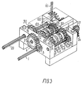
- the gearbox schematically shown in fig. 1 and also shown in fig. 3 has an input shaft or primary driven shaft 1 with a gear wheel 3 which is fixedly mounted on the shaft.
- the gear wheel 3 drives a gear wheel 4 which is fixedly mounted on another shaft 2 which is parallel with the primary driven shaft 1.
- the gear wheels 3 and 4 are in permanent engagement, and the two shafts 1 and 2 are thus rotationally ties to each other, and owing to the different sizes of the gear wheels 3 and 4 the shafts 1 and 2 have different speeds of rotation.
- these shafts 1 and 2 have the same function of driven shafts, and below the expression primary driven shaft is used for the shaft 1 and the expression secondary driven shaft for the shaft 2.
- the gearbox has an output shaft or driving shaft 20 with two fixed gear wheels 29, 30.
- the gear wheel 29 on the driving shaft 20 is in permanent rotational connection with gear wheels 28, 27, 26, 25, 23 and 21, and the gear wheel 30 on the driving shaft 20 is in permanent rotational connection with gear wheels 22 and 24.
- the gear wheels 21 and 22 are mounted rotatably on the secondary driven shaft 2 in fixed axial positions, and the gear wheels 23 and 24 are likewise mounted rotatably on the primary driven shaft 1 in fixed axial positions.
- the primary driven shaft 1 carries a first driving ring 41, which is rotationally tied to the shaft 1, and which can be slid axially on the shaft 1.
- the secondary driven shaft 2 likewise carries a second driving ring 42, which is identical with the first driving ring 41 and is rotationally tied to the shaft 2 and is axially slidable on the shaft 2.
- a driving ring 41 is shown in fig. 2 and consists of a pipe member 43 having two radially protruding flanges 44 on the outer side.
- the two flanges 44 define an annular guide groove 45 whose bottom is formed by a portion of the pipe member 43.
- Four claws 46 protrude in an axial direction from each of the flanges 44.
- the claws 46 are wedge-shaped and their tips face away from the flanges 44 concerned.
- the claws 46 are moreover in firm connection with the pipe member 43.
- the claws 46 are pointed and narrow, and each set of four claws defines angular gaps 47 between claws 46 which are considerably larger than the angular extent of the individual claw 46.
- the driving ring 41 has projections (not shown) on the inner side of the pipe member 43 to engage a corresponding, axially extending depression (not shown) in each of the driven shafts 1 and 2, so that, as mentioned, the driving rings 41 and 42 are in rotationally firm connection with the respective driven shafts 1 and 2 and are axially slidable on these.
- each of the flanges 44 having axially protruding claws 46 constitutes one clutch half of a claw clutch, as will be explained below.
- Fig. 2 also shows the other clutch half 50 for a claw clutch.
- the clutch half 50 consists of an outer pipe or ring member 51 having four wedge-shaped claws 52 on the inner side, each of which has substantially the same shape as the claws 46.
- the clutch half 50 moreover has an inner pipe or ring member 53 which is located coaxially with the outer pipe member 51, and by means of which the coupling half 50 may be mounted freely rotatably on a shaft.
- the pipe members 51 and 53 are contiguous via a common flange (not shown).
- Each of the claws 52 and the inner tube member 53 define between them a radial gap capable of receiving the end of the pipe member 43 on the driving ring 41 so that the claws 52 may be received in the angular gaps 47 between the claws 46.
- angular gaps 54 are present between the claws 52 in which the claws 46 may be received.
- the outer cylindrical surface 55 of the outer pipe member 51 may be provided with radially protruding teeth, so that the clutch half 50 serves as a gear wheel which may be mounted freely rotatably on a shaft. This is shown in fig. 3.
- the driving ring 41 and the clutch half 50 may be mounted on a common shaft on which the driving ring 41 is axially slidable, and the end of the pipe member 43 with the four claws 46 may be received in the gap between the outer pipe member 51 and the inner pipe member 53, thereby providing a claw clutch. Since both the claws 46 and the claws 52 in the coupling region are narrow and pointed and have large gaps, it will always be possible in practice to make such a coupling irrespective of the mutual angular position of the driving ring 41 and the clutch half 50.
- each of the gear wheels 21, 22, 23 and 24 are constructed like the clutch half 50 with radially protruding teeth and axially protruding claws 52.
- the driving rings 41 and 42 are axially slidable on the primary driven shaft 1 and the secondary driven shaft 2, respectively, so that, as described above, the claws 46 may be inserted into the angular gaps 54 between the claws 52.
- the gearbox has four claw clutches 11, 12, 13 and 14, which may be engaged individually.
- the first gear of the toy gearbox is selected with the claw clutch 11, and the transmission of rotational energy from the primary driven shaft 1 then takes place via the gear wheels 3 and 4 to the secondary driven shaft 2, which drives the second driving ring 42, from which the rotational energy is transmitted through the claw clutch 11 to the gear wheels 21, 23, 25, 26, 27, 28 and 29 to the driving shaft 20.
- the first driving ring 41 is slidable on the primary driven shaft 1 to engage the claw clutch 14 corresponding to the fourth gear of the toy gearbox, rotational energy being transmitted from the primary driven shaft 1 and the first driving ring 41 through the claw clutch to the gear wheels 24, 22 and 30, which drive the driving shaft 20.
- claw clutches 11, 12, 13 and 14 correspond to the first, the second, the third and the fourth gears of the toy gearbox, respectively.
- the toy gearbox is shown in fig. 1 in a position in which the four claw clutch gears 11, 12, 13 and 14 are all disengaged, so that no rotational movement can be transmitted from any of the driven shafts 1, 2 to the driving shaft 20, or vice versa.
- the two driving rings 41 and 42 here have their guide grooves 45 arranged opposite each other
- fig. 3 shows that the gearbox has a gear lever 61 which is mounted in a ball joint 63 centrally with respect to the shown position of the guide grooves 45 and out of the plane defined by the driven shafts 1 and 2.
- the gear lever can thus be tilted in the ball joint and has its movement restricted by an H-shaped guide 60.
- the gear lever is movable transversely in the central part of the H-shaped guide, and an engagement end 62 of the gear lever 61 may thus be engaged with a selected one of the guide grooves 45.
- the gear lever moves the driving ring concerned axially because of its engagement with the guide groove 45 concerned until the claw clutched concerned is engaged.
- the H-shaped guide 60 ensures that no more than one of the claw clutches is engaged at a time, since movement of the engagement end 62 of the gear lever from the guide groove of one driving ring to the guide groove of the other driving ring can only take place through the central portion of the H-shaped guide 60, where both driving rings are in the shown neutral position.
- the gear lever directly engages the guide grooves of the driving rings, i.e. without intermediate mechanisms.
- the gearbox may be expanded to three or optionally more parallel driven shafts equidistantly spaced from the ball joint of the gear lever, thereby increasing the number of selectable gear wheel transmissions.
- the shown toy gearbox is reciprocal so that the driving shaft 20 may be used as the driven shaft, and when the pair of gear wheels 3, 4 is omitted, the shown gearbox enables it to be chosen whether rotational energy is to be transmitted from the shaft 20 to the shaft 1 or to the shaft 2.
- the toy gearbox may hereby be used for driving mechanisms each of which is coupled to a respective one of the shafts 1 and 2, and these may then be driven one at a time or simultaneously.
Landscapes
- Engineering & Computer Science (AREA)
- General Engineering & Computer Science (AREA)
- Mechanical Engineering (AREA)
- Toys (AREA)
- Retarders (AREA)
- Mechanical Operated Clutches (AREA)
Abstract
Description
Claims (7)
- A toy gearbox comprisingan input, or primary driven shaft (1),an output, or driving shaft (20),selectable gear wheel transmissions (21-30) for transmission of rotational energy from the driven shaft (1) to the driving shaft (20),slidable driving means (41, 42) with a guide groove (45) and claw clutches (11-14) for selection of a particular gear wheel transmission (21-30), andgear shift means (61, 62) for engaging the guide groove (45) and sliding the driving means (41, 42) to engage a selected claw clutch (11-14) with an associated gear wheel transmission (21-30),
characterized in that the gearbox further comprisesa secondary driven shaft (2) located parallel to the primary driven shaft (1) and driven by the primary driven shaft (1), the secondary driven shaft (2) having driving means (42) with a guide groove (45) located in a position opposite the guide groove of the driving means (41) on the primary driving shaft (1), andthe gear shift means (61, 62) being slidable transversely to the direction of the driven shafts (1, 2) to engage the guide groove (45) of a driving means (41, 42) of a selected driven shaft (1, 2), and being axially slidable in the direction of the driven shafts (1, 2) to move the selected driving means (41, 42) axially, thereby engaging a selected claw clutch (11-14) with an associated gear wheel transmission (21-30). - A toy gearbox according to claim 1, characterized in that the shift means is a lever (61) which is mounted in a ball joint (63) centrally with respect to the guide grooves (45) of the driving means (41, 42) and out of the plane of the driven shafts (1, 2).
- A toy gearbox according to claim 2, characterized in that the movements of the lever are restricted by an H-shaped guide (60).
- A toy gearbox according to any one of claims 1 - 3 characterized in that the claws (46, 52) on each of the parts (41, 50) of the claw clutches (11-14) in the coupling region have a width which is considerably smaller than the corresponding gaps (54, 47) between the claws (52, 46) on the respective other clutch part (50, 41).
- A toy gearbox according to claim 4, characterized in that the claws (46, 52) are pointed with the tips facing the respective other clutch part (41, 50).
- A toy gearbox according to claims 4-5, characterized in that the claws (46, 52) are provided on an exterior cylindrical face and on an internal cylindrical face, respectively.
- A toy gearbox according to claim 6, characterized in that the cylindrical faces are surfaces of respective pipe or ring members (43, 51).
Applications Claiming Priority (4)
| Application Number | Priority Date | Filing Date | Title |
|---|---|---|---|
| DK1071/93 | 1993-09-22 | ||
| DK107193A DK170966B1 (en) | 1993-09-22 | 1993-09-22 | toy Box |
| DK107193 | 1993-09-22 | ||
| PCT/DK1994/000354 WO1995008375A1 (en) | 1993-09-22 | 1994-09-21 | A toy gearbox and a claw clutch therefor |
Publications (2)
| Publication Number | Publication Date |
|---|---|
| EP0675750A1 EP0675750A1 (en) | 1995-10-11 |
| EP0675750B1 true EP0675750B1 (en) | 1998-01-14 |
Family
ID=8100667
Family Applications (1)
| Application Number | Title | Priority Date | Filing Date |
|---|---|---|---|
| EP94926823A Expired - Lifetime EP0675750B1 (en) | 1993-09-22 | 1994-09-21 | Toy gearbox |
Country Status (7)
| Country | Link |
|---|---|
| EP (1) | EP0675750B1 (en) |
| JP (1) | JP3634365B2 (en) |
| AT (1) | ATE162091T1 (en) |
| DE (1) | DE69407951T2 (en) |
| DK (1) | DK170966B1 (en) |
| SG (1) | SG79177A1 (en) |
| WO (1) | WO1995008375A1 (en) |
Family Cites Families (7)
| Publication number | Priority date | Publication date | Assignee | Title |
|---|---|---|---|---|
| DE337933C (en) * | 1919-11-23 | 1921-02-02 | Zahnradfabrik Ges Mit Beschrae | coupling |
| US2543412A (en) * | 1942-08-07 | 1951-02-27 | Kegresse Adolphe Valentin | Change-speed transmission |
| US3529479A (en) * | 1967-02-03 | 1970-09-22 | Mattel Inc | Gear train and clutch for a self-propelled toy |
| US3475854A (en) * | 1967-02-03 | 1969-11-04 | Mattel Inc | Self-propelled crawling toy |
| FR2239082A5 (en) * | 1973-07-27 | 1975-02-21 | Sicopal | Steerable and reversible battery operated toy car - two cams on common shaft actuate respective control levers |
| JPS56125086A (en) * | 1980-03-04 | 1981-10-01 | Asahi Tsuushinki Kogyo Kk | Automatic speed change slope climbing device for model automobile |
| US4485587A (en) * | 1983-01-07 | 1984-12-04 | Gordon Barlow Design | Reversing mechanism for a toy motor driven wheeled vehicle |
-
1993
- 1993-09-22 DK DK107193A patent/DK170966B1/en not_active IP Right Cessation
-
1994
- 1994-09-21 SG SG9602606A patent/SG79177A1/en unknown
- 1994-09-21 JP JP50950695A patent/JP3634365B2/en not_active Expired - Lifetime
- 1994-09-21 AT AT94926823T patent/ATE162091T1/en not_active IP Right Cessation
- 1994-09-21 DE DE69407951T patent/DE69407951T2/en not_active Expired - Lifetime
- 1994-09-21 EP EP94926823A patent/EP0675750B1/en not_active Expired - Lifetime
- 1994-09-21 WO PCT/DK1994/000354 patent/WO1995008375A1/en not_active Ceased
Also Published As
| Publication number | Publication date |
|---|---|
| SG79177A1 (en) | 2001-03-20 |
| JPH08503642A (en) | 1996-04-23 |
| HK1004597A1 (en) | 1998-11-27 |
| DK107193A (en) | 1995-03-23 |
| WO1995008375A1 (en) | 1995-03-30 |
| ATE162091T1 (en) | 1998-01-15 |
| DE69407951T2 (en) | 1998-06-18 |
| EP0675750A1 (en) | 1995-10-11 |
| JP3634365B2 (en) | 2005-03-30 |
| DE69407951D1 (en) | 1998-02-19 |
| DK107193D0 (en) | 1993-09-22 |
| DK170966B1 (en) | 1996-04-09 |
Similar Documents
| Publication | Publication Date | Title |
|---|---|---|
| KR101205988B1 (en) | Transmission system | |
| EP3737481B1 (en) | A toy gearbox | |
| CN114270079B (en) | Gear selection drum device and transmission device having such a gear selection drum device | |
| US4735109A (en) | Semi-blocked transmission | |
| JPS63203951A (en) | automotive gearbox | |
| KR870000976B1 (en) | Auxiliary power transmission having synchronizing mechanism | |
| US5388472A (en) | Motor vehicle gearbox | |
| US4889003A (en) | Manual transmission gearset brake for synchronized engagement of a sliding gear | |
| WO1997033103A1 (en) | Motor vehicle gearbox | |
| US5687610A (en) | Toy gearbox and a claw clutch therefor | |
| JP2009108878A (en) | Meshing clutch | |
| US5479835A (en) | Reverse gear synchronizer | |
| HK1004597A1 (en) | Toy gearbox | |
| HK1004597B (en) | Toy gearbox | |
| KR101775245B1 (en) | Hi-Low synchro-device for power splitting type manual transmission | |
| US3980164A (en) | Transmission synchronizer and dog-clutch unit | |
| JP2016188678A (en) | Transmission | |
| JPH0874883A (en) | Blocking mechanism for splitter type auxiliary speed change section | |
| KR100597351B1 (en) | Manual transmission for rear wheel drive | |
| RU2825249C2 (en) | Gearshift mechanism with cam clutch | |
| KR101568754B1 (en) | Shifting apparatus for dual clutch transmission | |
| RU2762578C1 (en) | Gearbox for vehicles and vehicles containing such gearbox | |
| KR100412793B1 (en) | Manual transmission of vehicle | |
| JPS5884247A (en) | Gear transmission | |
| JPH0617713B2 (en) | Gear type transmission |
Legal Events
| Date | Code | Title | Description |
|---|---|---|---|
| PUAI | Public reference made under article 153(3) epc to a published international application that has entered the european phase |
Free format text: ORIGINAL CODE: 0009012 |
|
| 17P | Request for examination filed |
Effective date: 19950425 |
|
| AK | Designated contracting states |
Kind code of ref document: A1 Designated state(s): AT BE CH DE DK ES FR GB GR IE IT LI LU MC NL PT SE |
|
| 17Q | First examination report despatched |
Effective date: 19960419 |
|
| GRAG | Despatch of communication of intention to grant |
Free format text: ORIGINAL CODE: EPIDOS AGRA |
|
| GRAG | Despatch of communication of intention to grant |
Free format text: ORIGINAL CODE: EPIDOS AGRA |
|
| GRAH | Despatch of communication of intention to grant a patent |
Free format text: ORIGINAL CODE: EPIDOS IGRA |
|
| GRAH | Despatch of communication of intention to grant a patent |
Free format text: ORIGINAL CODE: EPIDOS IGRA |
|
| GRAA | (expected) grant |
Free format text: ORIGINAL CODE: 0009210 |
|
| AK | Designated contracting states |
Kind code of ref document: B1 Designated state(s): AT BE CH DE DK ES FR GB GR IE IT LI LU MC NL PT SE |
|
| PG25 | Lapsed in a contracting state [announced via postgrant information from national office to epo] |
Ref country code: IT Free format text: LAPSE BECAUSE OF FAILURE TO SUBMIT A TRANSLATION OF THE DESCRIPTION OR TO PAY THE FEE WITHIN THE PRE;WARNING: LAPSES OF ITALIAN PATENTS WITH EFFECTIVE DATE BEFORE 2007 MAY HAVE OCCURRED AT ANY TIME BEFORE 2007. THE CORRECT EFFECTIVE DATE MAY BE DIFFERENT FROM THE ONE RECORDED.SCRIBED TIME-LIMIT Effective date: 19980114 Ref country code: GR Free format text: LAPSE BECAUSE OF FAILURE TO SUBMIT A TRANSLATION OF THE DESCRIPTION OR TO PAY THE FEE WITHIN THE PRESCRIBED TIME-LIMIT Effective date: 19980114 Ref country code: FR Free format text: LAPSE BECAUSE OF FAILURE TO SUBMIT A TRANSLATION OF THE DESCRIPTION OR TO PAY THE FEE WITHIN THE PRESCRIBED TIME-LIMIT Effective date: 19980114 Ref country code: ES Free format text: THE PATENT HAS BEEN ANNULLED BY A DECISION OF A NATIONAL AUTHORITY Effective date: 19980114 Ref country code: AT Free format text: LAPSE BECAUSE OF FAILURE TO SUBMIT A TRANSLATION OF THE DESCRIPTION OR TO PAY THE FEE WITHIN THE PRESCRIBED TIME-LIMIT Effective date: 19980114 |
|
| REF | Corresponds to: |
Ref document number: 162091 Country of ref document: AT Date of ref document: 19980115 Kind code of ref document: T |
|
| REG | Reference to a national code |
Ref country code: CH Ref legal event code: NV Representative=s name: ISLER & PEDRAZZINI AG Ref country code: CH Ref legal event code: EP |
|
| REF | Corresponds to: |
Ref document number: 69407951 Country of ref document: DE Date of ref document: 19980219 |
|
| PG25 | Lapsed in a contracting state [announced via postgrant information from national office to epo] |
Ref country code: SE Free format text: LAPSE BECAUSE OF FAILURE TO SUBMIT A TRANSLATION OF THE DESCRIPTION OR TO PAY THE FEE WITHIN THE PRESCRIBED TIME-LIMIT Effective date: 19980414 Ref country code: PT Free format text: LAPSE BECAUSE OF FAILURE TO SUBMIT A TRANSLATION OF THE DESCRIPTION OR TO PAY THE FEE WITHIN THE PRESCRIBED TIME-LIMIT Effective date: 19980414 Ref country code: DK Free format text: LAPSE BECAUSE OF FAILURE TO SUBMIT A TRANSLATION OF THE DESCRIPTION OR TO PAY THE FEE WITHIN THE PRESCRIBED TIME-LIMIT Effective date: 19980414 |
|
| EN | Fr: translation not filed | ||
| REG | Reference to a national code |
Ref country code: IE Ref legal event code: FG4D Free format text: 78391 |
|
| PG25 | Lapsed in a contracting state [announced via postgrant information from national office to epo] |
Ref country code: LU Free format text: LAPSE BECAUSE OF NON-PAYMENT OF DUE FEES Effective date: 19980921 Ref country code: IE Free format text: LAPSE BECAUSE OF NON-PAYMENT OF DUE FEES Effective date: 19980921 |
|
| PLBE | No opposition filed within time limit |
Free format text: ORIGINAL CODE: 0009261 |
|
| STAA | Information on the status of an ep patent application or granted ep patent |
Free format text: STATUS: NO OPPOSITION FILED WITHIN TIME LIMIT |
|
| 26N | No opposition filed | ||
| PG25 | Lapsed in a contracting state [announced via postgrant information from national office to epo] |
Ref country code: MC Free format text: LAPSE BECAUSE OF NON-PAYMENT OF DUE FEES Effective date: 19990331 |
|
| REG | Reference to a national code |
Ref country code: GB Ref legal event code: IF02 |
|
| REG | Reference to a national code |
Ref country code: CH Ref legal event code: PCAR Free format text: ISLER & PEDRAZZINI AG;POSTFACH 1772;8027 ZUERICH (CH) |
|
| REG | Reference to a national code |
Ref country code: GB Ref legal event code: 732E |
|
| PGFP | Annual fee paid to national office [announced via postgrant information from national office to epo] |
Ref country code: DE Payment date: 20130918 Year of fee payment: 20 Ref country code: CH Payment date: 20130912 Year of fee payment: 20 Ref country code: NL Payment date: 20130910 Year of fee payment: 20 |
|
| PGFP | Annual fee paid to national office [announced via postgrant information from national office to epo] |
Ref country code: GB Payment date: 20130918 Year of fee payment: 20 |
|
| PGFP | Annual fee paid to national office [announced via postgrant information from national office to epo] |
Ref country code: BE Payment date: 20130912 Year of fee payment: 20 |
|
| REG | Reference to a national code |
Ref country code: DE Ref legal event code: R071 Ref document number: 69407951 Country of ref document: DE |
|
| REG | Reference to a national code |
Ref country code: CH Ref legal event code: PL |
|
| REG | Reference to a national code |
Ref country code: NL Ref legal event code: V4 Effective date: 20140921 |
|
| REG | Reference to a national code |
Ref country code: GB Ref legal event code: PE20 Expiry date: 20140920 |
|
| PG25 | Lapsed in a contracting state [announced via postgrant information from national office to epo] |
Ref country code: DE Free format text: LAPSE BECAUSE OF EXPIRATION OF PROTECTION Effective date: 20140923 |
|
| PG25 | Lapsed in a contracting state [announced via postgrant information from national office to epo] |
Ref country code: GB Free format text: LAPSE BECAUSE OF EXPIRATION OF PROTECTION Effective date: 20140920 |