EP0675573A2 - Connecteur de bord de carte avec blindage et protection de la tension de drain combinés - Google Patents
Connecteur de bord de carte avec blindage et protection de la tension de drain combinés Download PDFInfo
- Publication number
- EP0675573A2 EP0675573A2 EP95104478A EP95104478A EP0675573A2 EP 0675573 A2 EP0675573 A2 EP 0675573A2 EP 95104478 A EP95104478 A EP 95104478A EP 95104478 A EP95104478 A EP 95104478A EP 0675573 A2 EP0675573 A2 EP 0675573A2
- Authority
- EP
- European Patent Office
- Prior art keywords
- connector
- housing
- shield
- voltage drain
- contact
- Prior art date
- Legal status (The legal status is an assumption and is not a legal conclusion. Google has not performed a legal analysis and makes no representation as to the accuracy of the status listed.)
- Withdrawn
Links
Images


Classifications
-
- H—ELECTRICITY
- H01—ELECTRIC ELEMENTS
- H01R—ELECTRICALLY-CONDUCTIVE CONNECTIONS; STRUCTURAL ASSOCIATIONS OF A PLURALITY OF MUTUALLY-INSULATED ELECTRICAL CONNECTING ELEMENTS; COUPLING DEVICES; CURRENT COLLECTORS
- H01R12/00—Structural associations of a plurality of mutually-insulated electrical connecting elements, specially adapted for printed circuits, e.g. printed circuit boards [PCB], flat or ribbon cables, or like generally planar structures, e.g. terminal strips, terminal blocks; Coupling devices specially adapted for printed circuits, flat or ribbon cables, or like generally planar structures; Terminals specially adapted for contact with, or insertion into, printed circuits, flat or ribbon cables, or like generally planar structures
- H01R12/70—Coupling devices
- H01R12/71—Coupling devices for rigid printing circuits or like structures
- H01R12/72—Coupling devices for rigid printing circuits or like structures coupling with the edge of the rigid printed circuits or like structures
- H01R12/721—Coupling devices for rigid printing circuits or like structures coupling with the edge of the rigid printed circuits or like structures cooperating directly with the edge of the rigid printed circuits
-
- H—ELECTRICITY
- H01—ELECTRIC ELEMENTS
- H01R—ELECTRICALLY-CONDUCTIVE CONNECTIONS; STRUCTURAL ASSOCIATIONS OF A PLURALITY OF MUTUALLY-INSULATED ELECTRICAL CONNECTING ELEMENTS; COUPLING DEVICES; CURRENT COLLECTORS
- H01R13/00—Details of coupling devices of the kinds covered by groups H01R12/70 or H01R24/00 - H01R33/00
- H01R13/648—Protective earth or shield arrangements on coupling devices, e.g. anti-static shielding
- H01R13/658—High frequency shielding arrangements, e.g. against EMI [Electro-Magnetic Interference] or EMP [Electro-Magnetic Pulse]
Definitions
- the present invention relates to electrical connectors and, more particularly, to an electrical connector having a combined shielding and voltage drain protection assembly.
- U.S. Patents 4,985,870; 4,849,944 and 3,973,817 disclose ground pads on a printed circuit board at the outer ends of a card edge connection area that make electrical contact with a card edge connector before the rest of the contact pads make contact.
- U.S. Patent 5,035,631 discloses a shielded card edge connector.
- U.S. Patent 4,241,381 discloses ground pads above cut-outs on a printed circuit board.
- U.S. Patent 4,889,495 discloses a connector with different length terminals to establish a contact sequence when a card is inserted.
- a card edge connector comprising a housing, an electromagnetic shield, and a voltage drain contact.
- the housing has a card edge receiving area.
- the electromagnetic shield surrounds an exterior of the housing.
- the voltage drain contact is directly fixedly attached to the shield and suitably positioned relative to the housing to contact a drain pad on a printed circuit board inserted into the card edge receiving area.
- a card edge connector having a housing, signal contacts, and a protection assembly.
- the protection assembly comprises an electromagnetic shield and a voltage drain contact.
- the electromagnetic shield surrounds the housing.
- the voltage drain contact is directly fixedly attached to two end portions of the shield to thereby attach the end portions to each other at a same attachment point of the voltage drain contact to the shield.
- the protection assembly provides both shielding protection for the signal contacts and voltage drain protection from a printed circuit board being inserted into the connector.
- a card edge connector comprising a housing, signal contacts, and electromagnetic shield, and a system for draining electricity from a daughter printed circuit board being inserted into the housing.
- the signal contacts are connected to the housing.
- the electromagnetic shield surrounds the housing.
- the system for draining electricity can drain electricity from a daughter printed circuit board before electrical contact is made between the signal contacts and signal pads on the daughter printed circuit board.
- the system includes a voltage drain contact directly attached to the shield at an end of the housing.
- the voltage drain contact has a contact area located above a top of a center section of the housing.
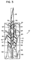
- FIG. 1-3 there is shown an electrical connector 10 incorporating features of the present invention.
- the present invention will be described with reference to the single embodiment shown in the drawings, it should be understood that the present invention can be used in a variety of different forms and types of alternate embodiments. In addition, any suitable size, shape, or type of elements or materials could be used.
- the connector 10 generally comprises a housing 12, electrical signal contacts 14, power contacts 15, and a combined shielding and voltage drain protection assembly 16.
- the connector 10 is a card edge connector that is used to removably mechanically and electrically connect a daughter printed circuit board 18 to a mother printed circuit board 20.
- the housing 12 is preferably made of dielectric material, such as a molded plastic or polymer material.
- the housing 12 has a center section 22 and two end sections 24, 25.
- the center section 22 has a card edge receiving area 26 for removably receiving the edge connection area 28 of the daughter board 18.
- the contacts 14 and 15 are also housed in the center section 22 with tail ends 30 extending out of the bottom of the housing 12.
- the end sections 24, 25 form ends to the housing, but also include elevated sections 32, 33 that extend up above the top surface 34 of the center section 22. Slots 36, 37 are provided in the end sections 24, 25 to accommodate the daughter board 18.
- the signal and power contacts 14, 15 can include any suitable type of spring contact. As is known in the art, the contacts 14, 15 have contact areas 38 in the receiving area 26 and solder tails 30. The contact areas 38 are adapted to make contact with signal pads 40 and power pads 41 on the edge connection area 28 of the daughter board 18 when the edge connection area 28 is inserted into the receiving area 26.
- the solder tails 30, in the embodiment shown, are through-hole solder tails. However, surface mount solder tails could also be used.
- the protection assembly 16 generally comprises two half shield members 42 and two voltage drain contacts 44.
- the shield members 42 are connected to each other with the housing 12 sandwiched therebetween.
- the shield members 42 are made of an electrically conductive material and include through-hole solder tails 46, top sections 48, and end sections 50.
- the two shield members 42 are suitable sized and shaped to interlock with the housing 12 and then be connected to each other by rivets 52.
- the top sections 50 overlie the top surface 34 of the housing 12 without blocking the entrance to the card edge receiving area 26.
- the end sections 50 each have two rivet holes 54 for the rivets 52. Raised outer lips 56 are also provided to contain the voltage drain contacts 44.
- the end sections 50 are suitably sized and shaped such that, when the shield members 42 are located on opposite longitudinal sides of the housing 12, they contact the opposite end sections of the opposing shield member.
- the two upper rivets only are attached to the end sections 50.
- the voltage drain contacts 44 are positioned and the two bottom rivets are attached. The two bottom rivets fixedly secure the voltage drain contacts 44 to the shield members 42.
- the voltage drain contacts 44 are made of electrically conductive material and have a general U-shape.
- a first portion 58 of the contacts 44 has rivet holes 60.
- a second portion 62 of the contacts 44 has opposing contact areas 64.
- the contacts 44 are positioned such that portions of both shield members 42 at both ends are located between the two arms of the contacts 44.
- the holes 60 are aligned with the bottom holes 54 and the bottom rivets 52 are then attached. This sandwiches portions of the end sections 50 between the arms of the contact 44.
- Widened area 66 of the contacts 44 are provided to accommodate the head and tail of the upper rivets.
- Two opposing spacer sections 68 are also provided on each contact 44 that contact the end sections 50 to space the contact areas 64 at a predetermined distance from each other.
- the voltage drain contacts 44 can merely be left off; the bottom rivets 52 merely connecting the shield members 42 to each other.
- fasteners other than rivets 52 could be used and, any suitable means to connect the voltage drain contacts 44 to the shield members and the shield members to each other could be used.
- more or less than two voltage drain contacts could be provided. More or less than two shield members could also be provided.
- the solder tails 46 of the shield members 42 are electrically connected to a ground on the mother printed circuit board 20. Because the shield members 42 substantially surround the housing 12, the shield members 42 are able to intercept electromagnetic interference to prevent false signal generation or true signal distortion in the signal contacts 14. In addition, because the voltage drain contacts are electrically connected to the shield members 42, the protection assembly 16 is also able to drain voltage from the daughter board 18, as the daughter board is being inserted into the connector 10, before contact is made between signal and power contacts 14, 15 and signal and power pads 40, 41.
- the card edge connection area 28 is inserted into receiving area 26.
- the daughter board 18 also has ground pads 70.
- the ground pads 70 are located separate from and on opposite ends of the card edge connection area 28.
- the contact areas 64 of the voltage drain contacts 44 are located a suitable distance above the contact areas 38 of the signal and power contacts 14, 15 such that, when the daughter board is inserted, the ground pads 70 make electrical contact with the drain contacts 44 before the signal pads 40 make contact with the signal contacts 14. This is illustrated in Fig. 3. This allows any residual electricity in the daughter board 18 to be removed.
- the slots 36, 37 in the housing end sections 24, 25 allow the daughter board 18 to be fully inserted into the connector 10.
- the housing end sections 24, 25 also protect the second portion 62 of the drain contacts 44. Raised outer lips 56 on the shield member end sections 50 keep the drain contacts properly positioned on the connector. Because the drain contacts 44 are fixedly connected to the shield members 42 only by the bottom rivets 52, a sufficient distance is provided between the bottom rivets 52 and the contact areas 64 to allow the arms of the drain contacts 44 to be resiliently deflected outward by the inserted mother board 18 without permanent deformation.
Landscapes
- Details Of Connecting Devices For Male And Female Coupling (AREA)
Applications Claiming Priority (2)
| Application Number | Priority Date | Filing Date | Title |
|---|---|---|---|
| US08/218,737 US5478259A (en) | 1994-03-28 | 1994-03-28 | Card edge connector with combined shielding and voltage drain protection |
| US218737 | 1994-03-28 |
Publications (2)
| Publication Number | Publication Date |
|---|---|
| EP0675573A2 true EP0675573A2 (fr) | 1995-10-04 |
| EP0675573A3 EP0675573A3 (fr) | 1995-12-27 |
Family
ID=22816318
Family Applications (1)
| Application Number | Title | Priority Date | Filing Date |
|---|---|---|---|
| EP95104478A Withdrawn EP0675573A3 (fr) | 1994-03-28 | 1995-03-27 | Connecteur de bord de carte avec blindage et protection de la tension de drain combinés. |
Country Status (2)
| Country | Link |
|---|---|
| US (1) | US5478259A (fr) |
| EP (1) | EP0675573A3 (fr) |
Cited By (4)
| Publication number | Priority date | Publication date | Assignee | Title |
|---|---|---|---|---|
| CN101510637A (zh) * | 2008-02-16 | 2009-08-19 | 哈廷电子有限公司及两合公司 | 具有接地连接的印刷板连接器 |
| WO2013003247A1 (fr) * | 2011-06-30 | 2013-01-03 | Tyco Electronics Corporation | Connecteur encartable |
| CN106816735A (zh) * | 2015-11-27 | 2017-06-09 | 技嘉科技股份有限公司 | 连接器外壳及连接器模块 |
| CN107204551A (zh) * | 2016-03-17 | 2017-09-26 | 富士康(昆山)电脑接插件有限公司 | 卡缘连接器 |
Families Citing this family (39)
| Publication number | Priority date | Publication date | Assignee | Title |
|---|---|---|---|---|
| US5989065A (en) * | 1995-05-05 | 1999-11-23 | The Boeing Company | High performance Mil-C-26500 |
| US5586893A (en) * | 1995-07-17 | 1996-12-24 | Itt Corporation | IC card connector shield grounding |
| US5577936A (en) * | 1995-09-28 | 1996-11-26 | Berg Technology, Inc. | Wafer retention in an electrical receptacle |
| JP3148855B2 (ja) * | 1996-03-01 | 2001-03-26 | モレックス インコーポレーテッド | 電気コネクタ |
| US6058018A (en) * | 1996-04-05 | 2000-05-02 | Berg Technology, Inc. | Electronic card |
| SG71046A1 (en) | 1996-10-10 | 2000-03-21 | Connector Systems Tech Nv | High density connector and method of manufacture |
| KR100512232B1 (ko) * | 1996-11-08 | 2005-09-05 | 에프씨아이 | 전자 카드 |
| TW387627U (en) * | 1996-11-30 | 2000-04-11 | Hon Hai Prec Ind Co Ltd | Electronic card connector |
| US6324076B1 (en) | 1997-05-22 | 2001-11-27 | Fci Americas Technology, Inc. | Electronic card with shield cover having tabs where each tab engages with recess of corresponding shield cover |
| US6078504A (en) * | 1997-10-08 | 2000-06-20 | Cisco Systems, Inc. | Universal adapter bracket for communications devices |
| US6220867B1 (en) * | 1998-11-17 | 2001-04-24 | Win Win Precision Industrial Co., Ltd. | Joining-structure for a high-density connector and interface module |
| US6408347B1 (en) | 1998-12-10 | 2002-06-18 | Cisco Technology, Inc. | Integrated multi-function adapters using standard interfaces through single a access point |
| CN2440270Y (zh) * | 1999-08-10 | 2001-07-25 | 莫列斯公司 | 连接器 |
| JP3899221B2 (ja) * | 2000-07-06 | 2007-03-28 | アルプス電気株式会社 | カード用コネクタ装置 |
| US6293826B1 (en) * | 2000-12-28 | 2001-09-25 | Hon Hai Precision Ind. Co., Ltd. | Electrical connector with metal side members and method of producing same |
| US6461169B1 (en) * | 2001-05-04 | 2002-10-08 | Intel Corporation | Interconnecting circuit modules to a motherboard using an edge connector with conductive polymer contacts |
| DE10302138A1 (de) * | 2002-02-19 | 2003-08-21 | Tyco Electronics Amp Gmbh | Steckverbinder |
| US6663402B1 (en) * | 2003-01-08 | 2003-12-16 | Hon Hai Precision Ind. Co., Ltd. | Electrical connector having grounding bridge |
| US7220151B2 (en) * | 2004-05-25 | 2007-05-22 | International Business Machines Corporation | Power connector |
| US8025515B2 (en) * | 2008-02-08 | 2011-09-27 | Ericsson Ab | Systems and methods for connecting a circuit board with a chassis |
| US8011950B2 (en) | 2009-02-18 | 2011-09-06 | Cinch Connectors, Inc. | Electrical connector |
| EP2824767B1 (fr) * | 2013-07-08 | 2019-10-09 | TE Connectivity Nederland B.V. | Système de connexion de barres omnibus destiné à être utilisé avec un système de distribution d'énergie et dispositif électrique comprenant un tel système de connexion |
| JP2016152084A (ja) * | 2015-02-16 | 2016-08-22 | タイコエレクトロニクスジャパン合同会社 | コネクタ組立体およびコネクタ |
| TWI604667B (zh) * | 2015-05-13 | 2017-11-01 | 技嘉科技股份有限公司 | Pci-e連接器外罩與pci-e連接器模組 |
| TWI601340B (zh) * | 2015-11-04 | 2017-10-01 | 技嘉科技股份有限公司 | 連接器外罩及連接器組件 |
| TWI539691B (zh) * | 2015-11-27 | 2016-06-21 | 技嘉科技股份有限公司 | 連接器外殼及連接器模組 |
| CN206004085U (zh) * | 2016-08-04 | 2017-03-08 | 富誉电子科技(淮安)有限公司 | 卡缘连接器 |
| CN106785543B (zh) * | 2016-08-19 | 2019-07-26 | 富士康(昆山)电脑接插件有限公司 | 卡缘连接器 |
| CN206211099U (zh) * | 2016-08-19 | 2017-05-31 | 富誉电子科技(淮安)有限公司 | 卡缘连接器 |
| CN106340738A (zh) * | 2016-09-12 | 2017-01-18 | 富士康(昆山)电脑接插件有限公司 | 卡缘连接器 |
| CN107870881B (zh) * | 2016-09-23 | 2021-04-16 | 伊姆西Ip控股有限责任公司 | 一种在存储设备中使用的转接卡 |
| DE102016120002A1 (de) * | 2016-10-20 | 2018-04-26 | Phoenix Contact Gmbh & Co. Kg | Kontakteinsatz für ein Steckverbinderteil |
| CN108346881B (zh) * | 2017-01-21 | 2021-04-20 | 富士康(昆山)电脑接插件有限公司 | 卡缘连接器 |
| CN110676619A (zh) * | 2018-07-03 | 2020-01-10 | 富士康(昆山)电脑接插件有限公司 | 卡缘连接器 |
| TWM590790U (zh) * | 2018-07-03 | 2020-02-11 | 英屬開曼群島商鴻騰精密科技股份有限公司 | 電連接器 |
| JP7163742B2 (ja) * | 2018-11-28 | 2022-11-01 | I-Pex株式会社 | 電気コネクタ |
| US10553971B1 (en) * | 2019-01-08 | 2020-02-04 | Te Connectivity Corporation | Card edge connector having a contact positioner |
| DE102019103772B4 (de) | 2019-02-13 | 2024-05-23 | Harting Electric Stiftung & Co. Kg | Schutzleiteranschluss |
| CN211428391U (zh) * | 2019-11-20 | 2020-09-04 | 富士康(昆山)电脑接插件有限公司 | 卡缘连接器 |
Citations (3)
| Publication number | Priority date | Publication date | Assignee | Title |
|---|---|---|---|---|
| EP0417899A1 (fr) * | 1989-09-11 | 1991-03-20 | Itt Industries Limited | Agencements de connexions électriques |
| US5035631A (en) * | 1990-06-01 | 1991-07-30 | Burndy Corporation | Ground shielded bi-level card edge connector |
| US5102350A (en) * | 1991-04-05 | 1992-04-07 | Molex Incorporated | Grounding electrical connector |
Family Cites Families (13)
| Publication number | Priority date | Publication date | Assignee | Title |
|---|---|---|---|---|
| GB1147037A (en) * | 1966-08-06 | 1969-04-02 | Ibm | Connector assembly |
| GB1481700A (en) * | 1974-06-06 | 1977-08-03 | Quantel Ltd | Interconnection of circuit boards |
| US3993935A (en) * | 1974-12-16 | 1976-11-23 | Xerox Corporation | Printed circuit board connection |
| US4179178A (en) * | 1978-02-02 | 1979-12-18 | Rca Corporation | Plug-in circuit cartridge with electrostatic charge protection |
| US4241381A (en) * | 1979-04-04 | 1980-12-23 | Amp Incorporated | Bus bar assembly for circuit cards |
| US4639056A (en) * | 1985-05-31 | 1987-01-27 | Trw Inc. | Connector construction for a PC board or the like |
| US4985870A (en) * | 1986-07-02 | 1991-01-15 | Dallas Semiconductor Corporation | Apparatus for connecting electronic modules containing integrated circuits and backup batteries |
| JPH0690872B2 (ja) * | 1986-08-18 | 1994-11-14 | 東京電気株式会社 | メモリ−カ−ド装置 |
| US4992052A (en) * | 1988-02-01 | 1991-02-12 | E. I. Du Pont De Nemours And Company | Modular connector system with high contact element density |
| JPH0769759B2 (ja) * | 1988-09-08 | 1995-07-31 | 三菱電機株式会社 | メモリカード用接続機構 |
| US4969824A (en) * | 1989-07-28 | 1990-11-13 | Amp Incorporated | Electrical connector |
| US4950172A (en) * | 1989-10-10 | 1990-08-21 | Itt Corporation | Connector with interceptor plate |
| US5141445A (en) * | 1991-04-30 | 1992-08-25 | Thomas & Betts Corporation | Surface mounted electrical connector |
-
1994
- 1994-03-28 US US08/218,737 patent/US5478259A/en not_active Expired - Fee Related
-
1995
- 1995-03-27 EP EP95104478A patent/EP0675573A3/fr not_active Withdrawn
Patent Citations (3)
| Publication number | Priority date | Publication date | Assignee | Title |
|---|---|---|---|---|
| EP0417899A1 (fr) * | 1989-09-11 | 1991-03-20 | Itt Industries Limited | Agencements de connexions électriques |
| US5035631A (en) * | 1990-06-01 | 1991-07-30 | Burndy Corporation | Ground shielded bi-level card edge connector |
| US5102350A (en) * | 1991-04-05 | 1992-04-07 | Molex Incorporated | Grounding electrical connector |
Cited By (7)
| Publication number | Priority date | Publication date | Assignee | Title |
|---|---|---|---|---|
| CN101510637A (zh) * | 2008-02-16 | 2009-08-19 | 哈廷电子有限公司及两合公司 | 具有接地连接的印刷板连接器 |
| EP2091109A2 (fr) * | 2008-02-16 | 2009-08-19 | Harting Electronics GmbH & Co. KG | Connecteur à fiches conductrices doté d'une connexion de masse |
| EP2091109A3 (fr) * | 2008-02-16 | 2012-11-07 | Harting Electronics GmbH & Co. KG | Connecteur à fiches conductrices doté d'une connexion de masse |
| WO2013003247A1 (fr) * | 2011-06-30 | 2013-01-03 | Tyco Electronics Corporation | Connecteur encartable |
| US8597056B2 (en) | 2011-06-30 | 2013-12-03 | Tyco Electronics Corporation | Card edge connector |
| CN106816735A (zh) * | 2015-11-27 | 2017-06-09 | 技嘉科技股份有限公司 | 连接器外壳及连接器模块 |
| CN107204551A (zh) * | 2016-03-17 | 2017-09-26 | 富士康(昆山)电脑接插件有限公司 | 卡缘连接器 |
Also Published As
| Publication number | Publication date |
|---|---|
| EP0675573A3 (fr) | 1995-12-27 |
| US5478259A (en) | 1995-12-26 |
Similar Documents
| Publication | Publication Date | Title |
|---|---|---|
| US5478259A (en) | Card edge connector with combined shielding and voltage drain protection | |
| EP0333386B1 (fr) | Connecteur électrique blindé pour montage sur circuit imprimé | |
| US5085590A (en) | Shielded stackable connector assembly | |
| EP0405454B1 (fr) | Elément coaxial de contact | |
| US4687263A (en) | Shielding kit for electrical connectors terminating multiconductor 360 degree shielded cable | |
| EP0347097B1 (fr) | Système de connecteur électrique | |
| CA1167129A (fr) | Kit pour transformer une ouverture dans un panneau en une prise blindee pour broches | |
| EP0188876A1 (fr) | Agencement d'un connecteur électrique blindé | |
| EP0371218A2 (fr) | Connecteur électrique | |
| EP0607910A2 (fr) | Assemblage de connecteur électrique blindé | |
| US6089882A (en) | Memory card connector with grounding clip | |
| EP0543300B1 (fr) | Connecteur électrique flottant blindé | |
| NL8000023A (nl) | Elektrisch verbindingsstelsel. | |
| EP0717467A2 (fr) | Connecteur de carte avec contact universel pour mise à la terre | |
| EP1032090A1 (fr) | Dispositif de connexion électrique blindé | |
| WO1988008627A1 (fr) | Element pourvu de pieces de montage destine a proteger un connecteur | |
| JPH11162578A (ja) | 電気コネクタ | |
| US6299476B1 (en) | Electrical connector with a flexible circuit and rigidizer subassembly and a spring | |
| EP0762324A2 (fr) | Connecteur de carte PC enfichable et carte PC équipée de ce connecteur | |
| EP0624928B1 (fr) | Ensemble connecteur électrique blindé | |
| EP0851540A2 (fr) | Connecteur pour montage sur une plaque de circuit imprimé avec dispositif de verrouillage multifonctionnel | |
| EP0308490B1 (fr) | Element pourvu de pieces de montage destine a proteger un connecteur | |
| JP3148855B2 (ja) | 電気コネクタ | |
| US4915652A (en) | Shielded electrical connector | |
| JPH0828253B2 (ja) | 接地式電気コネクタ |
Legal Events
| Date | Code | Title | Description |
|---|---|---|---|
| PUAI | Public reference made under article 153(3) epc to a published international application that has entered the european phase |
Free format text: ORIGINAL CODE: 0009012 |
|
| AK | Designated contracting states |
Kind code of ref document: A2 Designated state(s): BE DE ES FR GB IT NL SE |
|
| PUAL | Search report despatched |
Free format text: ORIGINAL CODE: 0009013 |
|
| AK | Designated contracting states |
Kind code of ref document: A3 Designated state(s): BE DE ES FR GB IT NL SE |
|
| STAA | Information on the status of an ep patent application or granted ep patent |
Free format text: STATUS: THE APPLICATION IS DEEMED TO BE WITHDRAWN |
|
| 18D | Application deemed to be withdrawn |
Effective date: 19960628 |